EP0225622A2 - Device for locking screw bolts against rotation - Google Patents
Device for locking screw bolts against rotation Download PDFInfo
- Publication number
- EP0225622A2 EP0225622A2 EP86117027A EP86117027A EP0225622A2 EP 0225622 A2 EP0225622 A2 EP 0225622A2 EP 86117027 A EP86117027 A EP 86117027A EP 86117027 A EP86117027 A EP 86117027A EP 0225622 A2 EP0225622 A2 EP 0225622A2
- Authority
- EP
- European Patent Office
- Prior art keywords
- holder
- drivers
- driver
- screw bolts
- adapter
- Prior art date
- Legal status (The legal status is an assumption and is not a legal conclusion. Google has not performed a legal analysis and makes no representation as to the accuracy of the status listed.)
- Granted
Links
- 238000005096 rolling process Methods 0.000 claims description 2
- 239000000969 carrier Substances 0.000 description 3
- 230000015572 biosynthetic process Effects 0.000 description 1
- 230000006835 compression Effects 0.000 description 1
- 238000007906 compression Methods 0.000 description 1
- 230000008878 coupling Effects 0.000 description 1
- 238000010168 coupling process Methods 0.000 description 1
- 238000005859 coupling reaction Methods 0.000 description 1
- 230000002349 favourable effect Effects 0.000 description 1
Images

Classifications
-
- F—MECHANICAL ENGINEERING; LIGHTING; HEATING; WEAPONS; BLASTING
- F16—ENGINEERING ELEMENTS AND UNITS; GENERAL MEASURES FOR PRODUCING AND MAINTAINING EFFECTIVE FUNCTIONING OF MACHINES OR INSTALLATIONS; THERMAL INSULATION IN GENERAL
- F16B—DEVICES FOR FASTENING OR SECURING CONSTRUCTIONAL ELEMENTS OR MACHINE PARTS TOGETHER, e.g. NAILS, BOLTS, CIRCLIPS, CLAMPS, CLIPS OR WEDGES; JOINTS OR JOINTING
- F16B39/00—Locking of screws, bolts or nuts
- F16B39/02—Locking of screws, bolts or nuts in which the locking takes place after screwing down
- F16B39/10—Locking of screws, bolts or nuts in which the locking takes place after screwing down by a plate, spring, wire or ring immovable with regard to the bolt or object and mainly perpendicular to the axis of the bolt
Definitions
- the invention relates to a device for preventing undesired rotation of screw bolts or the like provided at their ends with key engagement surfaces, in particular for large screw bolts.
- the object of the invention is to provide a practical, easy-to-use and simple device with which an undesired rotation of screw bolts can be prevented, in particular for needs of the type described above or similar. Further problems with which the invention is concerned arise itself from the respective explanation of the solution shown.
- the device according to the invention is characterized by the features specified in claim 1. As important components, it contains a holder, at least two drivers assigned to the latter and a number of individual adapters.
- Such a device makes it very easy to secure screw bolts in pairs against undesired turning. A torque that occurs on a screw bolt and seeks to turn it is reliably absorbed by the device and the torque support provided thereby. Depending on the need and the existing requirements, such a device can always remain in its place and then be practically part of a corresponding arrangement or device, or the device can only be used when necessary and for as long as is necessary for the operation to be carried out, such as unscrewing a nut.
- the drivers each extend through an opening of the holder, stops being provided in this area to limit the angular mobility.
- the stops can in particular be formed by inner surfaces of the opening itself.
- the opening expediently has the shape of a polygon, the driver or an extension of the same then having a corresponding shape with somewhat smaller dimensions.
- elastic centering elements are present which hold the driver in a rest or starting position relative to the holder.
- Such centering elements can be designed in different ways.
- spring-loaded thrust pieces are provided on or in the driver, which bear against inner surfaces of the holder.
- the adapters can be connected directly or indirectly to the holder or can be coupled thereto in such a way that they can be transported together with the holder and the drivers, in particular when the device is removed.
- Fig. 1 illustrates a particularly important application of the device, namely for bolts, expansion bolts, tie rods or the like.
- cover closures or flange connections for reactor vessels, pressure vessels and other high-strength connections, in particular in the manner of stud bolts are screwed with their lower end into a receiving thread of a base body and the like through holes in a cover, flange or the like. go through.
- a fastening nut is screwed onto a corresponding thread of the bolt, or the like against the cover, flange. sets.
- Such bolts are usually preloaded with a special device, i.e. stretched with a certain tensile force before the fastening nut is finally tightened. After removing the axial tensile force, a tension remains, so that the fastening nut or the like not only snugly on the cover, flange. is present, but presses the latter firmly against its support.
- Fig. 1 the upper parts of bolts 20 of the type mentioned above can be seen, which with their lower ends in a base body, not shown, e.g. a reactor vessel, are screwed in. They have key engagement surfaces at the upper end, here in the form of an external hexagon 21.
- Numeral 22 denotes a nut screwed onto an upper thread of the screw bolt 20, which serves as a system for an underlying, e.g. hydraulic tensioning or stretching device. This can contain one or more pistons which can be displaced upwards in cylinders, the uppermost piston acting on the contact nut 22.
- the upper contact nuts 22 must first be unscrewed from the bolts 20. It may happen that the nut is still tight and therefore does not turn on the bolt, but that the bolt is undesirably rotated together with the nut under the action of a torque applied to the latter.
- a plate-shaped holder 1 with carrying handles 2 is equipped with four sleeve-like carriers 3 in the advantageous embodiment shown.
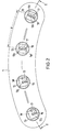
- the center distance A of the driver 3 is equal to the center distance of the bolts 20 from each other. Because the bolts are arranged on a bolt circle in the assumed case, the driver 3 are also to correspond the places of an arc in the holder. The outer shape of the latter can then also be curved, as shown in FIG. 2.
- Each driver 3 has a cylindrical, approximately pot-shaped lower part 3a with an internal toothing 4, a cylindrical middle part 3b and then, on a collar 3c, an upper projection 3d of approximately square outer shape with the side surfaces 5.
- the projection 3d passes through an opening delimited by surfaces 7 6 in the holder 1 (see. Fig. 3), which also has a square shape, but is slightly larger than the approach 3d, so that there is a small gap.
- the driver 3 has a small angular mobility in the sense of a rotation in one direction or the other about its longitudinal axis L from the starting position shown in FIG. 3. Such rotation is limited by the inner surfaces 7 acting as stops, against which the corner regions of the outer surfaces 6 of the projection 3d can come to rest.
- pressure pieces 10 loaded by compression springs 9 are provided in transverse bores 8 of the projection 3d, which are supported with their rounded heads on the inner surfaces 7 of the opening 6.
- the pressure pieces 10 are all shown as lying at the same height. However, an arrangement in two planes can also be provided, which results in particularly favorable centering or restoring forces.
- a head piece 13 is detachably connected, for example by, to the end face of the projection 3d of each driver 3 Screws, which has a larger diameter than the opening 6 in a round shape so that it rests on the top of the holder 1.
- the driver 3 is suspended to a certain extent on the holder 1.
- the distance between the head piece 13 and the collar 3c is somewhat larger than the thickness of the holder 1, so that there is also little mobility of the driver 3 relative to the holder 1 in the axial direction. But it is also possible to detachably attach the head pieces 13 to the holder 3.
- the number 12 designates adapters that form separate parts for themselves, but can be coupled to the drivers 3 or to the holder 1.
- Each adapter 12 has a lower part designed as a plug-on head 12a, which in the example shown has an internal hexagon 11, which corresponds to the external hexagon 21 at the upper end of each screw bolt 20. If the bolts have a different type or arrangement of key engagement surfaces, the formation of counter surfaces on or in the adapters is naturally a different one. For example, there may be a square or an elongated opening.
- the plug-on head 12a of the adapter 12 is also provided with external teeth 14 with which the internal teeth 4 of the driver 3 can engage.
- the teeth of the external toothing 14 of the adapter 12 and / or the teeth of the internal toothing 4 of the driver 3 are expediently pointed or chamfered at one end in order to enable particularly easy sliding into one another.
- a shaft 12b extends from the plug-on head 12a of the adapter 12 and is in the use shown in FIG. 1 Position of the device extends through the driver 3 and has a conical end 12c provided with an annular groove 15.
- a guide bush 16 is attached, in particular in the form of a roller or rolling element arrangement known per se, which, when the driver 3 is plugged onto the adapter 12, is pushed appropriately onto the shaft 12b and centers both parts. This is facilitated by the tapered end 12c of the shaft.
- a bolt 17 is pivotally mounted about a pin 18 such that it from a rest position (in the left half of Fig. 2) for engagement with the groove 15 of the shaft of the adapter 12 and thus in a Can be brought into the coupling position in which the adapter 12 is connected to the holder 1 for take-away by the latter (FIG. 1 and right half of FIG. 2).
- the part 3a of the driver 3 has at the lower end a cylindrical projection 19, the diameter of which is slightly smaller than the inner thread diameter of the nut 22, in such a way that it forms a guide part for the nut when it moves upwards when the bolt 20 is unscrewed.
- the device is handled as follows. First, the adapters 12, which are accommodated in cassettes for storage and transport, for example, are individually pushed onto the hexagon 21 of the screw bolts 20 by hand. Then the holder 1 is placed and lowered with the carriers 3, for example, also taken up by cassettes, the roller guides 16 or the like. slide onto the shafts 12b of the adapter 12 and then the teeth 4 and 14 come into engagement with each other. As already mentioned above, a slight rotation of the drivers 3 relative to the holder 1 is possible if the tooth position of the toothings 4 and 14 requires this how tooth pitch requires it. In the final state, the drivers 3 sit with part of the inner end face of the pot-shaped lower part 3a on the top of the plug-on head 12a or a shoulder formed thereon, as can be seen in FIG. 1.
- the bolts 20 are held by the mutual torque support caused by the holder 1, the carriers 3 and the adapter 12 and cannot rotate in an undesirable manner when the nuts 22 are loosened.
- the bolts 17 are pivoted into the ring grooves 15 on the shaft ends 12c of the adapter 12 (right part of FIG. 2). If the holder 1 is now raised on the carrying handles 2, the adapters 12 are removed from the screw bolts 20 together with the remaining parts. The nuts 22 can then be removed completely. The adapters 12 can be released by pivoting the latch 17 back and can be placed individually in their storage cassette.
- the device shown in the embodiment shown which is suitable for use with heavy screw bolts, has only such a weight that it can be handled by a man. Depending on the requirements, more or less than four can be in a holder Driver should be provided, in the minimum case two drivers.
Abstract
Eine Vorrichtung, mit der sich ein unerwünschtes Drehen von insbesondere grossen Schraubenbolzen verhindern lässt, weist einzeln auf die Enden der Schraubenbolzen (20) aufsetzbare Adapter (12) auf und enthält Mitnehmer (3), die auf die Adapter (12) aufschiebbar sind und jeweils eine mit einer Aussenverzahnung (14) der letzteren zum Eingriff bringbare Innenverzahnung (4) haben. Ausserdem ist ein Halter (1) vorhanden, in dem wenigstens zwei Mitnehmer (3) in einem dem Achsabstand der Schraubenbolzen (20) entsprechenden Mittenabstand mit geringer Winkelbeweglichkeit im ihre Längsachse aufgenommen sind.A device with which an undesired rotation of, in particular, large screw bolts can be prevented, has adapters (12) which can be placed individually on the ends of the screw bolts (20) and contains drivers (3) which can be pushed onto the adapters (12) and each have an internal toothing (4) which can be brought into engagement with an external toothing (14) of the latter. In addition, there is a holder (1) in which at least two drivers (3) are accommodated at a center distance corresponding to the center distance of the screw bolts (20) with little angular mobility in their longitudinal axis.
Description
Die Erfindung bezieht sich auf eine Vorrichtung zum Verhindern eines unerwünschten Drehens von an ihren Enden mit Schlüsselangriffsflächen versehenen Schraubenbolzen od.dgl., insbesondere für große Schraubenbolzen.The invention relates to a device for preventing undesired rotation of screw bolts or the like provided at their ends with key engagement surfaces, in particular for large screw bolts.
Es gibt Fälle, in denen auf einen Schraubenbolzen mittelbar oder unmittelbar Momente wirken, die den Schraubenbolzen zu drehen suchen, obgleich dies unerwünscht ist. Dies gilt insbesondere für nach Art von Stiftschrauben ausgebildete Schraubenbolzen, die in Aufnahmegewinde in einem Grundkörper eingeschraubt sind. Soll eine auf dem Schraubenbolzen befindliche Mutter abgeschraubt werden, so kann es vorkommen, daß diese festsitzt und dadurch den Schraubenbolzen mitzunehmen sucht. Solche Probleme bestehen u.a. bei großen Schraubenbolzen, wie etwa für Deckelverschlüsse von Druckbehältern u.dgl.There are cases in which a bolt acts directly or indirectly on moments that try to turn the bolt, although this is undesirable. This applies in particular to stud bolts designed in the manner of stud bolts, which are screwed into the receiving thread in a base body. If a nut on the screw bolt is to be unscrewed, it can happen that it is stuck and tries to take the bolt with it. Such problems exist, inter alia, with large screw bolts, such as for lid closures of pressure vessels and the like.
Aufgabe der Erfindung ist es, eine praktische, leicht zu handhabende und einfache Vorrichtung zu schaffen, mit der sich ein unerwünschtes Drehen von Schraubenbolzen verhindern läßt, insbesondere für Bedarfsfälle der vorstehend erläuterten oder ähnlichen Art. Weitere Probleme, mit denen sich die Erfindung befaßt, ergeben sich aus der jeweiligen Erläuterung der aufgezeigten Lösung.The object of the invention is to provide a practical, easy-to-use and simple device with which an undesired rotation of screw bolts can be prevented, in particular for needs of the type described above or similar. Further problems with which the invention is concerned arise itself from the respective explanation of the solution shown.
Die erfindungsgemäße Vorrichtung kennzeichnet sich durch die im Anspruch 1 angegebenen Merkmale. Sie enthält als wichtige Bestandteile einen Halter, wenigstens zwei dem letzteren zugeordnete Mitnehmer und eine Anzahl von einzelnen Adaptern.The device according to the invention is characterized by the features specified in
Durch eine solche Vorrichtung lassen sich Schraubenbolzen paarweise sehr einfach gegen ein unerwüschtes Drehen sichern. Ein an einem Schraubenbolzen auftretendes, ihn zu Drehen suchendes Moment wird durch die Vorrichtung und die dadurch gegebene Drehmomentstütze sicher aufgenommen. Je nach dem Bedarfsfall und den bestehenden Forderungen kann eine solche Vorrichtung ständig an ihrem Platz verbleiben und dann praktisch Bestandteil einer entsprechenden Anordnung oder Einrichtung sein, oder die Vorrichtung kann nur im Bedarfsfall und so lange zum Einsatz kommen, wie es für die jeweils durchzuführende Operation, etwa das Abschrauben einer Mutter, erforderlich ist.Such a device makes it very easy to secure screw bolts in pairs against undesired turning. A torque that occurs on a screw bolt and seeks to turn it is reliably absorbed by the device and the torque support provided thereby. Depending on the need and the existing requirements, such a device can always remain in its place and then be practically part of a corresponding arrangement or device, or the device can only be used when necessary and for as long as is necessary for the operation to be carried out, such as unscrewing a nut.
Bei einer vorteilhaften Ausführung erstrecken sich die Mitnehmer jeweils durch eine öffnung des Halters hindurch, wobei in diesem Bereich Anschläge zur Begrenzung der Winkelbeweglichkeit vorhanden sind. Die Anschläge können insbesondere durch Innenflächen der öffnung selbst gebildet sein. Zweckmäßig hat die öffnung die Form eines Vielecks, wobei dann der Mitnehmer oder ein Ansatz desselben eine entsprechende Form mit etwas kleineren Abmessungen hat.In an advantageous embodiment, the drivers each extend through an opening of the holder, stops being provided in this area to limit the angular mobility. The stops can in particular be formed by inner surfaces of the opening itself. The opening expediently has the shape of a polygon, the driver or an extension of the same then having a corresponding shape with somewhat smaller dimensions.
In weiterer Ausgestaltung der Vorrichtung sind elastische Zentrierelemente vorhanden, die den Mitnehmer relativ zum Halter in einer Ruhe- oder Ausgangsposition halten. Solche Zentrierelemente können verschiedenartig ausgebildet sein. Bei einer zweckmäßigen Ausführung sind federbelastete Druckstücke am oder im Mitnehmer vorgesehen, die an Innenflächen des Halters anliegen.In a further embodiment of the device, elastic centering elements are present which hold the driver in a rest or starting position relative to the holder. Such centering elements can be designed in different ways. In an expedient embodiment, spring-loaded thrust pieces are provided on or in the driver, which bear against inner surfaces of the holder.
Vorteilhaft sind die Adapter unmittelbar oder mittelbar an den Halter anschließbar oder mit diesem kuppelbar, derart, daß sie zusammen mit dem Halter und den Mitnehmern transportiert werden können, insbesondere beim Abnehmen der Vorrichtung.Advantageously, the adapters can be connected directly or indirectly to the holder or can be coupled thereto in such a way that they can be transported together with the holder and the drivers, in particular when the device is removed.
Weitere vorteilhafte Ausgestaltungen der Vorrichtung sind im übrigen in den Unteransprüchen angegeben.Further advantageous embodiments of the device are otherwise specified in the subclaims.
Einzelheiten, Merkmale und Vorteile der Erfindung ergeben sich weiterhin aus der nachfolgenden Erläuterung von Ausführungsbeispielen, aus der zugehörigen Zeichnung und aus den Ansprüchen.Details, features and advantages of the invention will further emerge from the following explanation of exemplary embodiments, from the associated drawing and from the claims.
Es zeigen:
- Fig. 1 eine Ausführung der Vorrichtung im Schnitt nach der Linie I - I in Fig. 2,
- Fig. 2 eine Draufsicht auf die Vorrichtung,
- Fig. 3 einen Schnitt nach der Linie III - III in Fig. 1,
- Fig. 4 einen Schnitt durch einen Adapter nach der Linie IV - IV in Fig. 1 und Fig. 5 eine Unteransicht eines Mitnehmers mit Blick in Richtung des Pfeiles V in Fig. 1.
- 1 is an embodiment of the device in section along the line I - I in Fig. 2,
- 2 is a plan view of the device,
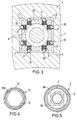
- 3 shows a section along the line III-III in FIG. 1,
- 4 shows a section through an adapter along the line IV-IV in FIG. 1, and FIG. 5 shows a bottom view of a driver with a view in the direction of the arrow V in FIG. 1.
Die Fig. 1 veranschaulicht einen besonders wichtigen Einsatzfall der Vorrichtung, und zwar bei Schraubenbolzen, Dehnschrauben, Zugankern od.dgl., wie sie bei Deckelverschlüssen oder Flanschverbindungen für Reaktorgefäße, Druckbehälter und bei sonstigen hochbelastbaren Verbindungen benutzt werden, insbesondere nach Art von Stehbolzen, die mit ihrem unteren Ende in ein Aufnahmegewinde eines Grundkörpers eingeschraubt werden und durch Löcher in einem Deckel, Flansch od.dgl. hindurchgehen. Dabei wird eine Befestigungsmutter auf ein entsprechendes Gewinde des Bolzens aufgeschraubt, die sich gegen den Deckel, Flansch od.dgl. legt. Derartige Schraubenbolzen werden meist mit einer besonderen Vorrichtung vorgespannt, d.h. mit einer bestimmten Zugkraft gedehnt, ehe die Befestigungsmutter endgültig angedreht wird. Nach dem Wegnehmen der axialen Zugkraft bleibt eine Spannung bestehen, so daß die Befestigungsmutter nicht nur satt am Deckel, Flansch od.dgl. anliegt, sondern den letzteren fest gegen seine Auflage preßt.Fig. 1 illustrates a particularly important application of the device, namely for bolts, expansion bolts, tie rods or the like. As they are used in cover closures or flange connections for reactor vessels, pressure vessels and other high-strength connections, in particular in the manner of stud bolts are screwed with their lower end into a receiving thread of a base body and the like through holes in a cover, flange or the like. go through. Here, a fastening nut is screwed onto a corresponding thread of the bolt, or the like against the cover, flange. sets. Such bolts are usually preloaded with a special device, i.e. stretched with a certain tensile force before the fastening nut is finally tightened. After removing the axial tensile force, a tension remains, so that the fastening nut or the like not only snugly on the cover, flange. is present, but presses the latter firmly against its support.
In Fig. 1 sind jeweils die oberen Teile von Schraubenbolzen 20 der vorstehend angesprochenen Art erkennbar, die mit ihren unteren Enden in einen nicht dargestellten Grundkörper, z.B. ein Reaktorgefäß, eingeschraubt sind. Sie weisen am oberen Ende Schlüsselangriffsflächen auf, hier in Form eines Außensechskants 21. Mit der Ziffer 22 ist jeweils eine auf ein oberes Gewinde des Schraubenbolzens 20 aufgeschraubte Mutter bezeichnet, die als Anlage für eine darunter befindliche, z.B hydraulische Spann- oder Dehnvorrichtung dient. Diese kann einen oder mehrere in Zylindern nach oben verschiebbare Kolben enthalten, wobei der oberste Kolben auf die Anlagemutter 22 wirkt.In Fig. 1, the upper parts of
Wenn die Schraubenspannvorrichtung nach dem Fertigstellen der Verbindung mit dem endgültigen Andrehen der nicht gezeigten Befestigungsmuttern von dem Deckel od.dgl. abgenommen werden soll, müssen zuerst die oberen Anlagemuttern 22 von den Bolzen 20 abgeschraubt werden. Dabei kann es vorkommen, daß die Mutter noch fest sitzt und sich deshalb nicht auf dem Bolzen dreht, sondern daß in unerwünschter Weise der Bolzen zusammen mit der Mutter unter der Wirkung eines auf die letztere aufgebrachten Drehmoments gedreht wird.If the screw tensioner or the like after completing the connection with the final tightening of the fastening nuts, not shown, from the cover. is to be removed, the
Um dies zu verhindern, wird die nachstehend im einzelnen erläuterte Vorrichtung benutzt.To prevent this, the device explained in detail below is used.
Ein plattenförmiger Halter 1 mit Traggriffen 2 ist bei der wiedergegebenen vorteilhaften Ausführung mit vier hülsenartigen Mitnehmern 3 ausgestattet. Der Mittenabstand A der Mitnehmer 3 ist gleich dem Achsabstand der Schraubenbolzen 20 voneinander. Weil die Schraubenbolzen im angenommenen Fall auf einem Lochkreis angeordnet sind, befinden sich auch die Mitnehmer 3 an entsprechenden Stellen eines Kreisbogens im Halters. Der letztere kann in seiner äußeren Form dann auch gekrümmt sein, wie Fig. 2 zeigt.A plate-
Jeder Mitnehmer 3 hat einen zylindrischen, etwa topfförmigen Unterteil 3a mit einer Innenverzahnung 4, einen zylindrischen Mittelteil 3b und anschließend an einen Bund 3c einen oberen Ansatz 3d von etwa quadratischer Außenform mit den Seitenflächen 5. Der Ansatz 3d geht durch eine von Flächen 7 begrenzte öffnung 6 im Halter 1 hindurch (vgl. Fig. 3), die ebenfalls eine quadratische Form hat, aber etwas größer als der Ansatz 3d ist, so daß ein kleiner Spalt besteht. Infolgedessen hat der Mitnehmer 3 eine geringe Winkelbeweglichkeit im Sinne einer Drehung in der einen oder anderen Richtung um seine Längsachse L aus der in Fig. 3 gezeigten Ausgangsposition. Eine solche Drehung wird durch die als Anschläge wirkenden Innenflächen 7 begrenzt, gegen die die Eckbereiche der Außenflächen 6 des Ansatzes 3d zur Anlage kommen können.Each
Um den Mitnehmer 3 in der Ruhe- oder Ausgangsposition mit Bezug auf die öffnung 6 zentriert zu halten, sind in Querbohrungen 8 des Ansatzes 3d von Druckfedern 9 belastete Druckstücke 10 vorgesehen, die sich mit ihren abgerundeten Köpfen an den Innenflächen 7 der Öffnung 6 abstützen. In Fig. 3 sind die Druckstücke 10 sämtlich als in gleicher Höhe liegend gezeigt. Es kann aber auch eine Anordnung in zwei Ebenen vorgesehen sein, wodurch sich besonders günstige Zentrier- bzw. Rückstellkräfte ergeben.In order to keep the
Mit der Stirnseite des Ansatzes 3d jedes Mitnehmers 3 ist ein Kopfstück 13 lösbar verbunden, z.B durch Schrauben, das bei runder Form einen größeren Durchmesser als die öffnung 6 hat, so daß es auf der Oberseite des Halters 1 aufliegt. Dadurch ist der Mitnehmer 3 gewissermaßen am Halter 1 aufgehängt. Der Abstand zwischen dem Kopfgstück 13 und dem Bund 3c ist etwas größer als die Dicke des Halters 1, so daß auch eine geringe Beweglichkeit des Mitnehmers 3 relativ zum Halter 1 in axialer REichtung besteht. Es ist aber auch möglich, die Kopfstücke 13 am Halters 3 lösbar zu befestigen.A
Mit der Ziffer 12 sind Adapter bezeichnet, die separate Teile für sich bilden, aber mit den Mitnehmern 3 bzw. mit dem Halter 1 gekuppelt werden können. Jeder Adapter 12 hat einen als Aufsteckkopf 12a ausgebildeten unteren Teil, der bei dem gezeigten Beispiel einen Innensechskant 11 aufweist, welcher dem Außensechskant 21 am oberen Ende jedes Schraubenbolzens 20 entspricht. Haben die Schraubenbolzen eine andere Art oder Anordnung von Schlüsselangriffsflächen, so ist naturgemäß auch die Ausbildung von Gegenflächen an oder in den Adaptern eines entsprechend andere. Es kann z.B. ein Vierkant oder eine längsliche öffnung vorhanden sein.The
Der Aufsteckkopf 12a des Adapters 12 ist ferner mit einer Außenverzahnung 14 versehen, mit der die Innenverzahnung 4 des Mitnehmers 3 zum Eingriff kommen kann. Zweckmäßig sind die Zähne der Außenverzahnung 14 des Adapters 12 und/oder die Zähne der Innenverzahnung 4 des Mitnehmers 3 jeweils an einem Ende angespitzt oder abgeschrägt, um ein besonders leichtes Ineinanderschieben zu ermöglichen.The plug-on
Vom Aufsteckkopf 12a des Adapters 12 geht ein Schaft 12b aus, der sich in der in Fig. 1 gezeigten Gebrauchsposition der Vorrichtung durch den Mitnehmer 3 hindurch erstreckt und ein konisches, mit einer Ringnut 15 versehenes Ende 12c hat. Im Mitnehmer 3 ist eine Führungsbüchse 16 angebracht, insbesondere in Form einer Rollen- oder Wälzkörperanordnung an sich bekannter Art, die sich beim Aufstecken des Mitnehmers 3 auf den Adapter 12 passend auf dessen Schaft 12b schiebt und beide Teile zentriert. Dies wird durch das konische Ende 12c des Schaftes erleichtert.A
Am Kopfstück 3a des Mitnehmers 3 ist jeweils ein Riegel 17 um einen Zapfen 18 schwenkbar angebracht, derart, daß er aus einer Ruheposition (in der linken Hälfte der Fig. 2) zum Eingriff mit der Nut 15 des Schaftes des Adapters 12 und damit in eine Kuppelposition gebracht werden kann, in der der Adapter 12 an den Halter 1 zur Mitnahme durch diesen angeschlossen ist (Fig. 1 und rechte Hälfte von Fig. 2).At the
Der Teil 3a des Mitnehmers 3 hat am unteren Ende einen zylindrischen Vorsprung 19, dessen Durchmesser geringfüging kleiner ist als der Gewindeinnendurchmesser der Mutter 22, derart, daß er einen Führungsteil für die Mutter bildet, wenn diese sich beim Abschrauben vom Bolzen 20 nach oben bewegt.The
Die Handhabung der Vorrichtung geschieht folgendermaßen. Zunächst werden die Adapter 12, die z.B. zur Aufbewahrung und zum Transport in Kassetten untergebracht sind, von Hand einzeln auf die Sechskante 21 der Schraubenbolzen 20 aufgesteckt. Dann wird der Halter 1 mit den beispielsweise ebenfalls von Kassetten aufgenommenen Mitnehmern 3 aufgesetzt und abgesenkt, wobei die Rollenführungen 16 od.dgl. sich auf die Schäfte 12b der Adapter 12 aufschieben und wobei dann auch die Verzahnungen 4 und 14 miteinander zum Eingriff kommen. Dabei ist, wie vorstehend bereits erwähnt, eine geringe Drehung der Mitnehmer 3 relativ zum Halter 1 möglich, wenn die Zahnstellung der Verzahnungen 4 und 14 dies erfordert Die Winkelbeweglichkeit der Mitnehmer 3 (jeweils Ansatz 3d in der öffnung 6) braucht nur so groß zu sein, wie die Zahnteilung dies erfordert. Im Endzustand sitzen die Mitnehmer 3 mit einem Teil der inneren Stirnfläche des topfförmigen Unterteils 3a auf der Oberseite des Aufsteckkopfes 12a bzw. einer daran gebildeten Schulter auf, wie dies Fig. 1 erkennen läßt.The device is handled as follows. First, the
In dieser Gebrauchsposition der Vorrichtung sind die Schraubenbolzen 20 durch die über den Halter 1, die Mitnehmer 3 und die Adapter 12 bewirkte gegenseitige Drehmomentabstützung festgehalten und können sich nicht in unerwünschter Weise drehen, wenn die Muttern 22 gelöst werden.In this position of use of the device, the
Zum Abnehmen der Vorrichtung werden die Riegel 17 in die Ringnuten 15 an den Schaftenden 12c der Adapter 12 eingeschwenkt (rechter Teil der Fig. 2). Wird jetzt der Halter 1 an den Traggriffen 2 angehoben, so werden die Adapter 12 zusammen mit den übrigen Teilen von den Schraubenbolzen 20 entfernt. Die Muttern 22 können dann ganz abgenommen werden. Die Adapter 12 lassen sich durch Zurückschwenken der Riegel 17 lösen und können einzeln in ihre Aufbewahrungskassette gelegt werden.To remove the device, the
Die in der dargestellten Ausführung u.a. für den Einsatz bei schweren Schraubenbolzen geeignete Vorrichtung hat nur ein solches Gewicht, daß sie von einem Mann gehandhabt werden kann. Je nach den Erfordernissen können in einem Halter auch mehr oder weniger als vier Mitnehmer vorgesehen sein, im Mindestfall zwei Mitnehmer.The device shown in the embodiment shown, which is suitable for use with heavy screw bolts, has only such a weight that it can be handled by a man. Depending on the requirements, more or less than four can be in a holder Driver should be provided, in the minimum case two drivers.
Alle in der vorstehenden Beschreibung erwähnten bzw. in der Zeichnung dargestellten Merkmale sollen, sofern der bekannte Stand der Technik es zuläßt, für sich allein oder auch in Kombinationen als unter die Erfindung fallend angesehen werden.All of the features mentioned in the above description or shown in the drawing, if the known prior art permits, should be regarded as falling within the scope of the invention on their own or in combinations.
Claims (12)
Applications Claiming Priority (2)
| Application Number | Priority Date | Filing Date | Title |
|---|---|---|---|
| DE8534790U | 1985-12-11 | ||
| DE8534790U DE8534790U1 (en) | 1985-12-11 | 1985-12-11 | Device for securing screw bolts against rotation |
Publications (3)
| Publication Number | Publication Date |
|---|---|
| EP0225622A2 true EP0225622A2 (en) | 1987-06-16 |
| EP0225622A3 EP0225622A3 (en) | 1988-06-15 |
| EP0225622B1 EP0225622B1 (en) | 1990-09-26 |
Family
ID=6788121
Family Applications (1)
| Application Number | Title | Priority Date | Filing Date |
|---|---|---|---|
| EP86117027A Expired - Lifetime EP0225622B1 (en) | 1985-12-11 | 1986-12-08 | Device for locking screw bolts against rotation |
Country Status (4)
| Country | Link |
|---|---|
| US (1) | US4739680A (en) |
| EP (1) | EP0225622B1 (en) |
| CA (1) | CA1276487C (en) |
| DE (2) | DE8534790U1 (en) |
Families Citing this family (7)
| Publication number | Priority date | Publication date | Assignee | Title |
|---|---|---|---|---|
| US4885834A (en) * | 1988-10-04 | 1989-12-12 | Beerman Paul J | Method and device for removing wheel nuts and cap nuts from the outer wheel of a dual-wheel double-nut system |
| GB9710447D0 (en) * | 1997-05-22 | 1997-07-16 | Rowledge John F | A device to prevent loosening of wheel nuts |
| US6588303B1 (en) | 2002-02-01 | 2003-07-08 | United Technologies Corporation | Anti-rotation device for fastener |
| GB2390993B (en) * | 2002-07-19 | 2004-07-28 | Allister Stewart | Improvements in or relating to a tool |
| GB2485226B (en) * | 2010-11-08 | 2016-12-21 | Siemag Tecberg Gmbh | Torque support for an integrated hoisting machine |
| DE102018107657A1 (en) | 2018-03-29 | 2019-10-02 | Frank Hohmann | Device for tightening screw connections |
| DE102018109703A1 (en) * | 2018-04-23 | 2019-10-24 | SCHAAF GmbH & Co. KG | Mounting arrangement for bracing fasteners at least comprising a rotation |
Citations (4)
| Publication number | Priority date | Publication date | Assignee | Title |
|---|---|---|---|---|
| DE351418C (en) * | 1920-01-27 | 1922-04-07 | John Horsfall | Screw locking by means of a wrench |
| DE2519695A1 (en) * | 1975-05-02 | 1976-11-11 | Karlheinz Froehlich | Vehicle wheel nut securing tags - comprises pairs of nuts joined by tags with profiled rings at ends |
| FR2374547A1 (en) * | 1976-12-15 | 1978-07-13 | Commissariat Energie Atomique | TWO-PIECE ASSEMBLY DEVICE |
| DE3309884A1 (en) * | 1983-03-17 | 1984-09-27 | Thanh-Son Dipl.-Ing. 1000 Berlin Le | Reusable positively-locking lock for a screw/nut of a detachable screw connection |
Family Cites Families (3)
| Publication number | Priority date | Publication date | Assignee | Title |
|---|---|---|---|---|
| US2102897A (en) * | 1936-09-16 | 1937-12-21 | H & H Machine & Motor Parts Co | Bolt-setting tool |
| FR1220097A (en) * | 1958-12-30 | 1960-05-23 | Bolt and Nut Presenter | |
| US3916734A (en) * | 1974-08-21 | 1975-11-04 | Anis S Sawan | Tool for use in removing automobile shock absorbers |
-
1985
- 1985-12-11 DE DE8534790U patent/DE8534790U1/en not_active Expired
-
1986
- 1986-12-08 EP EP86117027A patent/EP0225622B1/en not_active Expired - Lifetime
- 1986-12-08 DE DE8686117027T patent/DE3674552D1/en not_active Expired - Lifetime
- 1986-12-09 US US06/939,682 patent/US4739680A/en not_active Expired - Fee Related
- 1986-12-10 CA CA000524937A patent/CA1276487C/en not_active Expired - Lifetime
Patent Citations (4)
| Publication number | Priority date | Publication date | Assignee | Title |
|---|---|---|---|---|
| DE351418C (en) * | 1920-01-27 | 1922-04-07 | John Horsfall | Screw locking by means of a wrench |
| DE2519695A1 (en) * | 1975-05-02 | 1976-11-11 | Karlheinz Froehlich | Vehicle wheel nut securing tags - comprises pairs of nuts joined by tags with profiled rings at ends |
| FR2374547A1 (en) * | 1976-12-15 | 1978-07-13 | Commissariat Energie Atomique | TWO-PIECE ASSEMBLY DEVICE |
| DE3309884A1 (en) * | 1983-03-17 | 1984-09-27 | Thanh-Son Dipl.-Ing. 1000 Berlin Le | Reusable positively-locking lock for a screw/nut of a detachable screw connection |
Also Published As
| Publication number | Publication date |
|---|---|
| US4739680A (en) | 1988-04-26 |
| DE8534790U1 (en) | 1986-02-06 |
| DE3674552D1 (en) | 1990-10-31 |
| EP0225622B1 (en) | 1990-09-26 |
| EP0225622A3 (en) | 1988-06-15 |
| CA1276487C (en) | 1990-11-20 |
Similar Documents
| Publication | Publication Date | Title |
|---|---|---|
| DE4326939A1 (en) | Fastening element, in particular nut or screw, and tool for actuation | |
| DE2701744A1 (en) | OVERPRESSURE SAFETY | |
| DE2847478C2 (en) | Device for adjusting the closing distance between the slide and the machine bed of a press | |
| EP0225622B1 (en) | Device for locking screw bolts against rotation | |
| DE10302529B4 (en) | Clamping system for the tool holder of machine tools | |
| EP0344635B1 (en) | Device for trimming a container | |
| DE2919179C3 (en) | Anti-theft devices for motor vehicles | |
| DE6750366U (en) | CONTAINER LOCKING | |
| DE2825300B2 (en) | Jig | |
| DE2620996A1 (en) | LOCK NUT | |
| DE1958614A1 (en) | Universal key | |
| DE3317146A1 (en) | Spline gear | |
| DE2802293C3 (en) | Tensioning device for chain strands | |
| DE3637566C2 (en) | ||
| DE69936587T2 (en) | Flange-type toothed safety plate | |
| DE3344240A1 (en) | Nut | |
| DE3515383A1 (en) | Holding device | |
| DE3723554C2 (en) | Connection of a bearing ring of a large roller bearing of a rotating platform or the like to an undercarriage or the like | |
| DE8525840U1 (en) | Device for securing screw bolts against rotation | |
| DE3005309A1 (en) | Gap closing rail profile between form panels - has nuts on threaded bolts pressing holed fish-plates against panels | |
| DE2828470C3 (en) | Fastening device for a wheel, in particular an agricultural tractor, on an axle | |
| DE3043494C2 (en) | ||
| DE2046067C (en) | Prestressable screw connection | |
| DE7731209U1 (en) | SCHMITZ RING FOR ROTARY PRINTERS | |
| DE2947485A1 (en) | Detachable leg clamp to table - has eccentric sleeve with spanner faces turned on bolt against leg end |
Legal Events
| Date | Code | Title | Description |
|---|---|---|---|
| PUAI | Public reference made under article 153(3) epc to a published international application that has entered the european phase |
Free format text: ORIGINAL CODE: 0009012 |
|
| AK | Designated contracting states |
Kind code of ref document: A2 Designated state(s): DE FR GB IT SE |
|
| PUAL | Search report despatched |
Free format text: ORIGINAL CODE: 0009013 |
|
| AK | Designated contracting states |
Kind code of ref document: A3 Designated state(s): DE FR GB IT SE |
|
| RHK1 | Main classification (correction) |
Ipc: F16B 39/10 |
|
| 17P | Request for examination filed |
Effective date: 19881005 |
|
| 17Q | First examination report despatched |
Effective date: 19890529 |
|
| GRAA | (expected) grant |
Free format text: ORIGINAL CODE: 0009210 |
|
| AK | Designated contracting states |
Kind code of ref document: B1 Designated state(s): DE FR GB IT SE |
|
| ITF | It: translation for a ep patent filed |
Owner name: BARZANO' E ZANARDO MILANO S.P.A. |
|
| GBT | Gb: translation of ep patent filed (gb section 77(6)(a)/1977) | ||
| REF | Corresponds to: |
Ref document number: 3674552 Country of ref document: DE Date of ref document: 19901031 |
|
| PGFP | Annual fee paid to national office [announced via postgrant information from national office to epo] |
Ref country code: SE Payment date: 19901126 Year of fee payment: 5 |
|
| ET | Fr: translation filed | ||
| ITTA | It: last paid annual fee | ||
| PLBE | No opposition filed within time limit |
Free format text: ORIGINAL CODE: 0009261 |
|
| STAA | Information on the status of an ep patent application or granted ep patent |
Free format text: STATUS: NO OPPOSITION FILED WITHIN TIME LIMIT |
|
| 26N | No opposition filed | ||
| PG25 | Lapsed in a contracting state [announced via postgrant information from national office to epo] |
Ref country code: SE Effective date: 19911209 |
|
| EUG | Se: european patent has lapsed |
Ref document number: 86117027.2 Effective date: 19920704 |
|
| PGFP | Annual fee paid to national office [announced via postgrant information from national office to epo] |
Ref country code: GB Payment date: 19961129 Year of fee payment: 11 |
|
| PGFP | Annual fee paid to national office [announced via postgrant information from national office to epo] |
Ref country code: DE Payment date: 19961204 Year of fee payment: 11 |
|
| PGFP | Annual fee paid to national office [announced via postgrant information from national office to epo] |
Ref country code: FR Payment date: 19961219 Year of fee payment: 11 |
|
| PG25 | Lapsed in a contracting state [announced via postgrant information from national office to epo] |
Ref country code: GB Free format text: LAPSE BECAUSE OF NON-PAYMENT OF DUE FEES Effective date: 19971208 |
|
| PG25 | Lapsed in a contracting state [announced via postgrant information from national office to epo] |
Ref country code: FR Free format text: THE PATENT HAS BEEN ANNULLED BY A DECISION OF A NATIONAL AUTHORITY Effective date: 19971231 |
|
| GBPC | Gb: european patent ceased through non-payment of renewal fee |
Effective date: 19971208 |
|
| PG25 | Lapsed in a contracting state [announced via postgrant information from national office to epo] |
Ref country code: DE Free format text: LAPSE BECAUSE OF NON-PAYMENT OF DUE FEES Effective date: 19980901 |
|
| REG | Reference to a national code |
Ref country code: FR Ref legal event code: ST |
|
| PG25 | Lapsed in a contracting state [announced via postgrant information from national office to epo] |
Ref country code: IT Free format text: LAPSE BECAUSE OF NON-PAYMENT OF DUE FEES;WARNING: LAPSES OF ITALIAN PATENTS WITH EFFECTIVE DATE BEFORE 2007 MAY HAVE OCCURRED AT ANY TIME BEFORE 2007. THE CORRECT EFFECTIVE DATE MAY BE DIFFERENT FROM THE ONE RECORDED. Effective date: 20051208 |