EP0224330B1 - Schnecken-Venturirohr-Fördersystem für hohe Geschwindigkeit und Verfahren zum Fördern von Schüttgut - Google Patents
Schnecken-Venturirohr-Fördersystem für hohe Geschwindigkeit und Verfahren zum Fördern von Schüttgut Download PDFInfo
- Publication number
- EP0224330B1 EP0224330B1 EP86308164A EP86308164A EP0224330B1 EP 0224330 B1 EP0224330 B1 EP 0224330B1 EP 86308164 A EP86308164 A EP 86308164A EP 86308164 A EP86308164 A EP 86308164A EP 0224330 B1 EP0224330 B1 EP 0224330B1
- Authority
- EP
- European Patent Office
- Prior art keywords
- barrel
- venturi
- plenum chamber
- pressure
- venturi pipe
- Prior art date
- Legal status (The legal status is an assumption and is not a legal conclusion. Google has not performed a legal analysis and makes no representation as to the accuracy of the status listed.)
- Expired - Lifetime
Links
Images

Classifications
-
- B—PERFORMING OPERATIONS; TRANSPORTING
- B65—CONVEYING; PACKING; STORING; HANDLING THIN OR FILAMENTARY MATERIAL
- B65G—TRANSPORT OR STORAGE DEVICES, e.g. CONVEYORS FOR LOADING OR TIPPING, SHOP CONVEYOR SYSTEMS OR PNEUMATIC TUBE CONVEYORS
- B65G53/00—Conveying materials in bulk through troughs, pipes or tubes by floating the materials or by flow of gas, liquid or foam
- B65G53/04—Conveying materials in bulk pneumatically through pipes or tubes; Air slides
- B65G53/06—Gas pressure systems operating without fluidisation of the materials
- B65G53/08—Gas pressure systems operating without fluidisation of the materials with mechanical injection of the materials, e.g. by screw
Definitions
- the present invention relates to apparatus and methods for conveying bulk materials in the form of particles through a conduit, such as pipeline or hose, and more particularly to apparatus and methods in which the particulate material is first transported at high speed through a barrel by an auger conveyor, and then inserted within an envelope of pressurized flowing gas adjacent to the exit end of the barrel to continuously pneumatically propel the material through the conduit.
- Pneumatic conveying systems having auger conveyor sections are known in the art and have been in use for many years for transporting various particulate materials, such as pulverized coal, portland cement, grain, pulverized ore, etc., through pipelines and other conduits.
- Such systems which are described, for example, in U.S. Patents Nos.
- 1,553,539, 1,941,512, 1,941,573, 2,299,470, 3,370,890, 3,602,552 and 3,693,842 typically comprise a motor driven auger conveyor rotatably mounted within a barrel, a gravity-fed hopper for supplying particulate material to the auger conveyor through an opening in the barrel, and a mixing chamber situated at the discharge end of the barrel where the material ejected by the auger conveyor is subjected to one or more jets of pressurized air or other gas. The mixture of material and gas thus formed is propelled by the pressurized gas through a conduit connected to the mixing chamber.
- Pneumatic conveying systems for particulate materials have also been devised in which the mixing of material with the gas takes place in a venturi pipe through which pressurized gas flows.
- venturi conveying systems such as those described in U.S. Patents Nos. 3,186,769 and 4,009,912, have also been in use for many years in a variety of conveying applications.
- the particulate material to be mixed with the gas is supplied to the venturi pipe via a chute having a discharge end located near the constriction of the venturi pipe, where a vacuum (negative pressure) created by the high velocity gas flow therein acts to draw the material from the chute into the venturi pipe.
- a vacuum (negative pressure) created by the high velocity gas flow therein acts to draw the material from the chute into the venturi pipe.
- the transport rate in a conventional venturi conveying system is difficult to control and is subject to variations on account of changes in the properties of the material being conveyed, such as density, moisture content, particle size, etc.
- a conventional venturi conveying system may not provide a satisfactory material-to-air conveyance ratio for materials that are -not sufficiently free flowing in the chute to allow the negative pressure in the venturi pipe to draw such materials from
- blowback occurs when there is a blockage in the conduit that results in excessive pressure in the conduit and produces an undesirable back flow of the gas and product into the hopper in the auger conveyor type system and into the chute in the venturi type system.
- Known solutions to the blowback problem have included the use of a flapper valve or an air lock in the auger barrel or in the chute of the venturi type system to prevent back flow of gas and product when the pressure in the conduit becomes excessively high.
- the conveying apparatus disclosed therein includes: an auger conveyor rotatable mounted within a barrel; a hopper from supplying particulate material to the conveyor; a motor for rotating the conveyor so as to transport the material therealong; a plenum chamber surrounding the barrel near one end thereof; a venturi pipe coupled to the plenum chamber enclosing the first end of the barrel, the venturi pipe having a tapered section; a jet member located within the venturi pipe; a blower for introducing a pressurized gas into the plenum chamber; and a flexible conduit coupled to the outlet of the venturi pipe.
- apparatus for conveying particulate material including:
- a method of conveying particulate material including the steps of:
- the auger venturi conveying system 100 includes a cylindrical barrel 101 supported on a base 102.
- the barrel 101 which has an inside diameter of approximately 12.7 cm, houses a cantilevered 122 cm long, 10.1 cm diameter auger conveyor 103.
- the auger conveyor 103 has a shaft 104 which projects through a bearing 105 supported by suitable bushings 106 (only one of which is illustrated in Fig. 1) and extends out of the far end 107 of the barrel 101.
- the bearing 105 and the bushings 106 serve as rotatable mounting and the main support for the auger conveyor 103, which extends throughout the length of the barrel 101.
- the shaft 104 of the auger conveyor 103 is coupled to a 1140 kgm/s (15 H.P.) motor (402 in Fig. 4) through a pulley 109 and a drive belt 110.
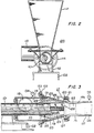
- Material to be transported by the conveying system 100 is supplied by a vertically disposed, funnel-shaped hopper 111 mounted to the support frame 112 of the barrel 101, as shown in Fig. 2.
- the material in the hopper 111 drops onto the auger conveyer 103 through an opening 138 in the barrel 101.
- the auger conveyor 103 is driven by the motor (not shown) to rotate in a direction which causes the flights 113 of the auger to push the material towards the discharge end 108 of the barrel 101, such that the material is ejected from the discharge end at a rate and velocity determined by the rotational speed of the auger conveyor 103 and the pitch of the flights 113.
- the rotational speed of the auger conveyor 103 is advantageously in the range of 750 r.p.m.
- the characteristics of the flights 113 are adjusted in a known manner to the material to be transported. Inasmuch as all of the components of the auger conveyor section of the system 100 are conventional, the details of the design and construction of such components need not be further described.
- annular plenum chamber 114 Located adjacent to the discharge end 108 of the barrel 101 is an annular plenum chamber 114 surrounding the barrel 101 and having an inside diameter of approximately 25,4 cm (10 inches).
- the plenum chamber 114 has a port 115 connected to a blower 116 (illustrated schematically) for introducing pressurized air into the plenum chamber 114.
- a venturi pipe 117 Coupled to the plenum chamber 114 is a venturi pipe 117 enclosing the discharge end 108 of the barrel 101.
- the venturi pipe 117 is constructed in two sections 118 and 119 coupled together by means of flanges 120 and 121 on each section, which are fastened by bolts.
- One of the sections 118 of the venturi pipe 117 is tapered and leads into a constriction 122 in the other narrower section 119.
- the section 119 also has a tapered section 119a of increasing cross section downstream of the constriction 122.
- the narrower section 119 is coupled, as by welding for example, to a conduit 136, such as a pipeline or a hose.
- the tapered section 118 has a conically shaped interior surface 123, which is coaxial with the barrel 101.
- a jet member 124 attached to the discharge end 108 of the barrel 101 by a set screw 125 and extending approximately to the constriction 122.
- the jet member 124 has a conically shaped outer surface 126, which is also coaxial with the barrel 101.
- the outer surface 126 of the jet member 124 is appropriately shaped to conform with the interior surface 123 of the tapered section 118 to form a narrow annular passage 127 between the plenum chamber 114 and the constriction 122 of the venturi pipe 117.
- the angle formed by the interior surface 123 of the tapered section 118 and that formed by the outer surface 126 of the jet member 124 are advantageously made equal and in the range of 11 ° to 15° to the axis of the barrel 101.
- the flight 113 of the auger conveyor 103 extend substantially to the end of the jet member 124 adjacent the constriction 122. This avoids the formation of a product plug at the exit end of the auger and facilitates discharge of the material into the fluid stream.
- the blower 116 is of a conventional type which provides airflow at a volume rate and pressure suited to the material being conveyed and the length of conduit used. For example, a volume flow rate of approximately 21,2 cubic meter per minute (750 C.F.M.) and a pressure in the range of 12 to 15 psig are suitable for transporting anthracite color through a pipeline of approximately 100 m (300 feet). It is advantageous to use blowers that provide volume flow rates in the range of 17 to 42,5 cubic meter per minute (600 C.F.M. to 1500 C.F.M.). The pressure required to maintain such volume flow rates ordinarily depends on the length of the conduit and the properties of the material being transported. Although blowers are preferred to minimize costs, if the required pressure is greater than that which is available from blowers, compressors may be used to provide the pressurized air to the plenum chamber 114.
- the jet member 124 has an axial bore 128 for channeling the material supplied from the barrel 101 to the constriction 122, or more specifically, into the vena contracta of the venturi flow.
- a vacuum (negative pressure) in the range of 305 to 381 mm (12 to 15 inches) of Hg is created in he constriction 122 and the bore 108 of the jet member when no material is being injected into the constriction. Because the vacuum is the greatest along the axis of the constriction 122 and falls off with distance away from the axis, the material particles that are introduced into the constriction 122 are accelerated in such a manner that the larger and denser particles tend to converge towards the center of the airstream. Moreover, mixing of the particulate material with the airstream in such a manner produces minimal turbulence in the mixture flowing from the venturi pipe 117. For that reason, when such a mixture is propelled through the conduit contact of the material with the conduit walls is minimized.
- a pressure difference in the range of 0,21 to 0,74 kg/sq cm (3 to 10 psi) should be maintained between the plenum chamber 114 and a region 137 of the conduit 136 adjacent the constriction 122 for advantageous operation of the conveying system 100.
- Such pressure difference may be adjusted by varying the width of the annular passage 127 of the venturi pipe 117.
- the position of the tapered section 118 with respect to the jet member 124 is made adjustable by making the coupling between the plenum chamber 114 and the tapered section 118 in the form of a thread fitting 129 attached to the plenum chamber by a flange 132 that is bolted to a corresponding flange 133 of the plenum chamber, as shown in Fig. 3.
- the threads 130 on the fitting 129 mate with threads 131 on the interior surface of the wide end of the tapered section 118 to allow the tapered section to be screwed onto the fitting.
- the width of the annular passage 127 may be adjusted by turning the tapered section 118 in one or the other direction to cause the pressure difference between the plenum chamber 114 and the conduit region 137 adjacent the constriction 122 to be within the aforementioned range.
- Conventional dial type pressure gauges 134 and 135 mounted in fittings in the walls of the plenum chamber 114 and the conduit region 137, respectively, are provided to facilitate the making of such adjustments.
- blowback may be prevented by monitoring the pressure difference and by reducing the supply rate of material to the auger conveyor if the pressure difference goes below a specified value, for example 0,07 kg/sq cm (1 psi). The material supply rate is restored when the pressure difference returns to the aforementioned range after the blockage or clog in the conduit clears itself.
- the monitoring of the pressure difference and the reduction of the material supply rate may be carried out by an operator observing the pressure gauges 134 and 135 and controlling the rotational speed of the auger conveyor 103, or it may be carried out automatically using a mechanical, electromechanical or electronic control system.
- FIG. 4 there is shown a auger venturi conveying system 400 similar to that of Figs. 1, 2 and 3 but with the addition of a control system for automatically prevention blowback.
- the speed of the motor 402 driving the auger conveyor 103 is controllable by a signal from a controller 404.
- the plenum chamber 114 and the conduit region 137 adjacent the constriction 122 of the venturi pipe 117 are provided with pressure transducers 405 and 406, respectively, mounted in fittings in the walls of those regions.
- the pressure transducers 405 and 406 may be commercially available units which provide electrical signals corresponding to the pressures in the respective regions where they are located.
- the signals from the pressure transducers 405 and 406 are provided to the controller 404 which is designed to determine whether the pressure difference between the plenum chamber 114 and the conduit region 137 is above or below a specified valve, e.g., 0,07 kg/sq cm (1 psi). If the pressure difference is equal to or above the specified valve, the controller 404 provides an appropriate signal to the motor 402 for causing the motor to operate at its normal speed. If, however, the pressure difference is below the specified value, the controller 404 provides an appropriate signal to the motor 402 to significantly slow or stop the motor.
- a specified valve e.g., 0,07 kg/sq cm (1 psi
- the controller 404 may be designed to provide continuous control over the speed of the motor 402, in which case the signal from the controller to the motor causes the motor speed to be proportional to the pressure difference, for speeds up to the normal speed. Since the design and construction of a controller for providing the above-specified control functions is well known to one skilled in the control circuitry art, the details of the controller need not be further described.
- the above-described auger venturi conveyor systems 100 and 400 in accordance with the present invention are capable of continuously transporting particulate materials having random particle sizes up to particle dimensions equal to the distance between the auger flights.
- a typical air-to-material conveying ratio for those systems is 14 pounds of solid per one pound of air over a conveying distance of 400 feet.
- conveying systems according to the present invention provide highly efficient removal of any moisture from the material being conveyed, owing to a mechanical shearing effect that occurs as the material is accelerated through the negative pressure zone of the venturi pipe which draws moisture from the surfaces of the particles being accelerated.
- conveying systems according to the present invention afford effective blowback prevention without the use of flapper valves, air locks or product-plug seals.
- the exit speed of the material from the auger may be varied to optimize material throughput, product drying, and the like, but generally the auger rotational speed is preferably selected so that the material exit speed approaches that of the air flow through the conveying line.
- the interior surface of the tapered section of the venturi pipe and the outer surface of the jet member need not be conical but may have other tapered shapes, and the width of the annular passage between the plenum chamber and the constriction need not be uniform.
- means other than screw threads may be used to provide adjustment of the position of the tapered section of the venturi pipe with respect to the jet member, and gases other than air may be used for transporting the particulate material.
- the diameter and other dimensions of the auger barrel, verturi, etc. may be varied as needed to suit the rise of the conduit through which the material is to be conveyed.
Claims (11)
Priority Applications (1)
| Application Number | Priority Date | Filing Date | Title |
|---|---|---|---|
| AT86308164T ATE51379T1 (de) | 1985-10-22 | 1986-10-21 | Schnecken-venturirohr-foerdersystem fuer hohe geschwindigkeit und verfahren zum foerdern von schuettgut. |
Applications Claiming Priority (2)
| Application Number | Priority Date | Filing Date | Title |
|---|---|---|---|
| US06/790,056 US4711607A (en) | 1985-10-22 | 1985-10-22 | High speed auger venturi system and method for conveying bulk materials |
| US790056 | 1985-10-22 |
Publications (2)
| Publication Number | Publication Date |
|---|---|
| EP0224330A1 EP0224330A1 (de) | 1987-06-03 |
| EP0224330B1 true EP0224330B1 (de) | 1990-03-28 |
Family
ID=25149523
Family Applications (1)
| Application Number | Title | Priority Date | Filing Date |
|---|---|---|---|
| EP86308164A Expired - Lifetime EP0224330B1 (de) | 1985-10-22 | 1986-10-21 | Schnecken-Venturirohr-Fördersystem für hohe Geschwindigkeit und Verfahren zum Fördern von Schüttgut |
Country Status (8)
| Country | Link |
|---|---|
| US (1) | US4711607A (de) |
| EP (1) | EP0224330B1 (de) |
| JP (1) | JPS62100321A (de) |
| AT (1) | ATE51379T1 (de) |
| CA (1) | CA1284808C (de) |
| DE (1) | DE3669864D1 (de) |
| ES (1) | ES2014987B3 (de) |
| GR (1) | GR3000609T3 (de) |
Families Citing this family (45)
| Publication number | Priority date | Publication date | Assignee | Title |
|---|---|---|---|---|
| JP2607146B2 (ja) * | 1989-05-12 | 1997-05-07 | 宇部興産株式会社 | 混気圧送装置 |
| US5087155A (en) * | 1990-04-25 | 1992-02-11 | Blowhard Pneumatic Services Inc. | Apparatus for introducing bulk materials into pneumatic conveying line |
| US5125771A (en) * | 1990-04-25 | 1992-06-30 | Blowhard Pneumatic Services, Inc. | Apparatus for introducing bulk materials into pneumatic conveying line |
| EP0707931A3 (de) * | 1994-10-18 | 1996-10-30 | Putzmeister Maschf | Vorrichtung zur pneumatischen Förderung von trockenem Fördergut |
| DE19514326C2 (de) * | 1995-04-18 | 1998-04-02 | Wolfgang Peltzer | Vorrichtung zum Einblasen von teilchenförmigen Dämmstoffen |
| US5718539A (en) * | 1995-05-19 | 1998-02-17 | Ba/Lf Holdings, L.C. | Boundary air/laminar flow conveying system with air reduction cone |
| US5863155A (en) * | 1995-05-19 | 1999-01-26 | Segota; Darko | Boundary air/laminar flow conveying system |
| CA2163586A1 (en) * | 1995-11-23 | 1997-05-24 | Robert Frederick Eady | System and method for transporting bulk materials |
| US6155751A (en) * | 1997-12-11 | 2000-12-05 | Ecotech Systems International, Ltd. | Flow development chamber for creating a vortex flow and a laminar flow |
| WO1999046051A1 (en) | 1998-03-13 | 1999-09-16 | Terra Systems, Inc. | Pneumatic accelerator for multi-phase material acceleration, dispersion and conveyance |
| AUPP789898A0 (en) * | 1998-12-23 | 1999-01-21 | Birrus Engineering Pty Ltd | Conveying |
| AU756496B2 (en) * | 1998-12-23 | 2003-01-16 | Birrus International Pty Ltd | Conveying particulate material in a pressurised gas |
| US7082955B2 (en) * | 2001-12-04 | 2006-08-01 | Ecotechnology, Ltd. | Axial input flow development chamber |
| US6659118B2 (en) | 2001-12-04 | 2003-12-09 | Ecotechnology, Ltd. | Flow development chamber |
| AU2002352931A1 (en) * | 2001-12-04 | 2003-06-17 | Ecotechnology, Ltd. | Flow development chamber |
| AU2003294546A1 (en) * | 2002-12-26 | 2004-07-22 | Alvin J. Stumborg | Apparatus for dispensing particulate material into a pneumatic conveying line |
| US7488141B2 (en) * | 2004-07-14 | 2009-02-10 | Halliburton Energy Services, Inc. | Automated control methods for dry bulk material transfer |
| DE102005003620A1 (de) * | 2005-01-26 | 2006-08-03 | Lanxess Deutschland Gmbh | Verfahren und Vorrichtung zur pneumatischen Förderung von schwerfließendem Schüttgut |
| WO2008089710A1 (en) * | 2007-01-26 | 2008-07-31 | Schenck Process, S.R.O. | A device for administration of compressible materials into pneumatic transport system namely pipeline, the method of such administration to transport material, compression and usage |
| DE102007050679A1 (de) * | 2007-10-21 | 2009-04-23 | Voxeljet Technology Gmbh | Verfahren und Vorrichtung zum Fördern von Partikelmaterial beim schichtweisen Aufbau von Modellen |
| DE102008008419A1 (de) * | 2008-02-09 | 2009-09-10 | Uhde Gmbh | Verfahren und Vorrichtung zur Aufnahme und Übergabe von fein- bis grobkörnigen Feststoffen aus einem Behälter in ein System höheren Druckes |
| US8006613B2 (en) | 2008-07-16 | 2011-08-30 | Lyco Manufacturing, Inc. | Transfer mechanism for use with a food processing system |
| US11560276B2 (en) | 2008-07-16 | 2023-01-24 | Lyco Manufacturing, Inc. | Transfer mechanism for use with a food processing system |
| US9060530B2 (en) * | 2008-07-16 | 2015-06-23 | Lyco Manufacturing, Inc. | Transfer mechanism for use with a food processing system |
| JP5770087B2 (ja) | 2008-07-25 | 2015-08-26 | スパイン ビュー, インコーポレイテッド | ケーブルベースの創傷清拭のためのシステムおよび方法 |
| US9168047B2 (en) | 2009-04-02 | 2015-10-27 | John T. To | Minimally invasive discectomy |
| US8801739B2 (en) | 2009-04-17 | 2014-08-12 | Spine View, Inc. | Devices and methods for arched roof cutters |
| JP5204863B2 (ja) * | 2010-10-04 | 2013-06-05 | 茂 竹島 | 食品搾りかす送出装置 |
| DE102010056346A1 (de) | 2010-12-29 | 2012-07-05 | Technische Universität München | Verfahren zum schichtweisen Aufbau von Modellen |
| DE102011000675B4 (de) * | 2011-02-11 | 2019-07-04 | Di Matteo Förderanlagen GmbH & Co. KG | Verfahren und Vorrichtung zum Fördern eines Schüttgutstromes |
| US20130322972A1 (en) * | 2012-06-05 | 2013-12-05 | LFIP Holdings Pty. Ltd. | Pneumatic air conveyance technology |
| US9382066B2 (en) | 2013-02-15 | 2016-07-05 | Proton Power, Inc. | Sliding wall hopper methods, systems, and devices |
| WO2014127180A1 (en) * | 2013-02-15 | 2014-08-21 | Proton Power, Inc. | Sliding wall hopper methods, systems, and devices |
| EP2966014B1 (de) * | 2014-07-10 | 2017-02-01 | IBAU Hamburg Ingenieurgesellschaft | Schneckenpumpe zum Fördern von Schüttgütern |
| US10080571B2 (en) | 2015-03-06 | 2018-09-25 | Warsaw Orthopedic, Inc. | Surgical instrument and method |
| CN105947682A (zh) * | 2016-06-12 | 2016-09-21 | 天津市实达电力设备有限公司 | 一种改进结构的物料连续输送泵 |
| CN106672560A (zh) * | 2017-01-03 | 2017-05-17 | 无锡职业技术学院 | 一种加压式喂料机 |
| CN106697627B (zh) * | 2017-01-18 | 2018-12-25 | 江苏云腾高新科技有限公司 | 用于生产绿色环保pvc发泡板的自动螺旋粉末上料机 |
| CN108689184B (zh) * | 2018-06-05 | 2024-03-22 | 深圳市一胜百机械设备制造有限公司 | 直立粉末上料机 |
| ES2948196T3 (es) * | 2018-09-18 | 2023-09-01 | Smidth As F L | Aparato para transportar material pulverizado |
| US11561006B2 (en) | 2020-10-23 | 2023-01-24 | M.S.T. Corporation | Apparatus and process for a kinetic feed plug screw |
| CN112718299B (zh) * | 2021-04-02 | 2021-07-09 | 成都天本地源科技有限公司 | 一种立式间歇性粉粒物料稀相喷射输送装置 |
| CN113899415B (zh) * | 2021-12-10 | 2022-02-22 | 山东华盛环境工程有限公司 | 一种用于空气能热泵的流量监测装置 |
| CN114701860A (zh) * | 2022-03-18 | 2022-07-05 | 安徽科技学院 | 一种气压传输式粮食输送机 |
| CN116588604B (zh) * | 2023-07-17 | 2023-09-15 | 新乡市和协饲料机械制造有限公司 | 一种能够实现饲料快速进出料的螺旋输送器 |
Family Cites Families (52)
| Publication number | Priority date | Publication date | Assignee | Title |
|---|---|---|---|---|
| US531160A (en) * | 1894-12-18 | Colin w | ||
| US749206A (en) * | 1904-01-12 | Fuel-feeding device | ||
| US267318A (en) * | 1882-11-14 | Pneumatic conveyer | ||
| US1185118A (en) * | 1911-08-04 | 1916-05-30 | Concrete Mixing And Conveying Company | Method of mixing and transporting concrete. |
| US1053014A (en) * | 1912-06-05 | 1913-02-11 | Peter L Cron | Pneumatic plastering-machine. |
| US1243892A (en) * | 1917-01-29 | 1917-10-23 | Green Eng Co | Intake-fitting for conveying systems. |
| US1454979A (en) * | 1918-11-21 | 1923-05-15 | Locomotive Pulverized Fuel Com | Fuel-feeding apparatus |
| US1553539A (en) * | 1919-10-08 | 1925-09-15 | Fuller Lehigh Co | Conveying pulverized material |
| US1675090A (en) * | 1923-06-25 | 1928-06-26 | Henry J Burns | Pneumatic conveyer |
| US1567383A (en) * | 1923-08-17 | 1925-12-29 | Power Stevens Fan Devices Comp | Delivery mechanism |
| US1789096A (en) * | 1924-08-02 | 1931-01-13 | Ind & Utility Conveyor Company | Pneumatic conveyer |
| US1566325A (en) * | 1924-09-24 | 1925-12-22 | Ingersoll Rand Co | Mortar projector |
| US1686713A (en) * | 1926-11-18 | 1928-10-09 | Int Comb Eng Corp | Blower nozzle for transport lines |
| US1796215A (en) * | 1927-06-04 | 1931-03-10 | Peikert Heinrich | Air-pressure conveyer |
| US1772244A (en) * | 1927-06-11 | 1930-08-05 | Int Comb Eng Corp | Device for transporting finely-divided materials |
| US1804565A (en) * | 1928-08-15 | 1931-05-12 | Fuller Co | Portable pump |
| US1889480A (en) * | 1931-01-21 | 1932-11-29 | Charles F Kelley | Continuous feed gun for concrete or plastic materials |
| US1924675A (en) * | 1931-05-08 | 1933-08-29 | Bernert George | Pneumatic conveyer |
| US1941572A (en) * | 1932-05-20 | 1934-01-02 | Fuller Co | Conveying apparatus |
| US1941573A (en) * | 1932-09-20 | 1934-01-02 | Fuller Co | Conveying system |
| US2141920A (en) * | 1937-05-22 | 1938-12-27 | Fuller Co | Conveying apparatus |
| US2247448A (en) * | 1940-08-02 | 1941-07-01 | Fuller Co | Conveying apparatus |
| US2268991A (en) * | 1940-08-02 | 1942-01-06 | Fuller Co | Conveying apparatus |
| US2272564A (en) * | 1941-01-28 | 1942-02-10 | Mrs E M Kuever | Dry cement conveyer |
| US2299470A (en) * | 1941-06-18 | 1942-10-20 | Fuller Co | Conveying apparatus |
| GB685365A (en) * | 1948-03-13 | 1953-01-07 | Standard Oil Dev Co | Improvements in or relating to method and apparatus for handling finely divided solid materials |
| US2695265A (en) * | 1949-04-27 | 1954-11-23 | Kellogg M W Co | Injection mixer for use in catalytic hydrocarbon conversion processes |
| GB686718A (en) * | 1950-10-30 | 1953-01-28 | Frederick John Cherewick | Improvements in and relating to air flow conveyors |
| US2821346A (en) * | 1953-04-23 | 1958-01-28 | Majac Inc | Injector for impact pulverizer or the like |
| US2916441A (en) * | 1956-10-29 | 1959-12-08 | Exxon Research Engineering Co | Process and apparatus for controlling the rate of addition of fluidized particles |
| US2971679A (en) * | 1958-11-28 | 1961-02-14 | Pavia Charles | Apparatus for processing materials |
| US3186769A (en) * | 1962-02-01 | 1965-06-01 | Union Tank Car Co | Pumping system |
| US3152839A (en) * | 1962-04-18 | 1964-10-13 | Howard C Edwards | Abrasive materials handling draft inducer |
| GB1020543A (en) * | 1962-04-30 | 1966-02-23 | Amalgamated Roadstone Corp Ltd | Containers for powdered and granular materials |
| US3268266A (en) * | 1964-03-26 | 1966-08-23 | Rex Chainbelt Inc | Pneumatic conveyor system and method |
| US3372958A (en) * | 1966-05-02 | 1968-03-12 | York Mfg Company | Automatic feeder for pneumatic conveying lines |
| US3370890A (en) * | 1966-10-26 | 1968-02-27 | Morgan Mason Edward | Pneumatic conveyors for dry portland cement |
| US3424501A (en) * | 1967-07-11 | 1969-01-28 | Henry T Young | Conveying system |
| US3460869A (en) * | 1967-10-09 | 1969-08-12 | Joseph Stanley Herr | Air lock |
| US3588180A (en) * | 1969-08-11 | 1971-06-28 | Joseph S Herr | Air lock |
| US3602552A (en) * | 1969-09-17 | 1971-08-31 | Mason Edward Morgan | Dry flow pumps |
| US3693842A (en) * | 1970-08-17 | 1972-09-26 | Westinghouse Electric Corp | Aerated powder pump |
| DE2149262A1 (de) * | 1971-10-02 | 1973-04-05 | Waeschle Maschf Gmbh | Aufgabevorrichtung fuer pneumatische hochdruckfoerderanlagen zur kontinuierlichen foerderung von pulverigen oder koernigen guetern |
| US4009912A (en) * | 1974-11-04 | 1977-03-01 | Joseph Mraz | Pneumatic conveying apparatus and method |
| US3975058A (en) * | 1975-05-12 | 1976-08-17 | Lafayette Engineering & Manufacturing, Inc. | Particulate solids pump |
| US4111492A (en) * | 1976-02-03 | 1978-09-05 | Joseph Mraz | Pneumatic conveying apparatus and method |
| SU659484A2 (ru) * | 1977-12-26 | 1979-04-30 | Всесоюзный Научно-Исследовательский Институт Комбикормовой Промышленности | Питатель дл пневматического транспортировани сыпучих материалов |
| SU779211A1 (ru) * | 1978-08-08 | 1980-11-15 | Центральное Проектное Конструкторско- Технологическое Бюро Цветной Металлургии Казахской Сср | Пневматический винтовой питатель |
| JPS5596400A (en) * | 1979-01-13 | 1980-07-22 | Kyoei Zoki Kk | Jet pump for conveying solid matter |
| DD143753A1 (de) * | 1979-05-25 | 1980-09-10 | Johannes Uhlmann | Aufgabevorrichtung fuer die pneumatische foerderung von schuettgut |
| DE3114372A1 (de) * | 1981-04-09 | 1982-12-30 | Maschinenfabrik Karl Brieden & Co, 4630 Bochum | "pneumatische foerderanlage fuer dammbaustoff im untertagebetrieb" |
| JPS57207826A (en) * | 1981-06-17 | 1982-12-20 | Hideo Nagasaka | Measuring device for flow rate of pulverulent body |
-
1985
- 1985-10-22 US US06/790,056 patent/US4711607A/en not_active Expired - Lifetime
-
1986
- 1986-09-08 JP JP61211355A patent/JPS62100321A/ja active Pending
- 1986-10-16 CA CA000520692A patent/CA1284808C/en not_active Expired - Lifetime
- 1986-10-21 AT AT86308164T patent/ATE51379T1/de active
- 1986-10-21 EP EP86308164A patent/EP0224330B1/de not_active Expired - Lifetime
- 1986-10-21 ES ES86308164T patent/ES2014987B3/es not_active Expired - Lifetime
- 1986-10-21 DE DE8686308164T patent/DE3669864D1/de not_active Expired - Lifetime
-
1990
- 1990-06-28 GR GR90400422T patent/GR3000609T3/el unknown
Also Published As
| Publication number | Publication date |
|---|---|
| DE3669864D1 (de) | 1990-05-03 |
| EP0224330A1 (de) | 1987-06-03 |
| JPS62100321A (ja) | 1987-05-09 |
| US4711607A (en) | 1987-12-08 |
| GR3000609T3 (en) | 1991-09-27 |
| ES2014987B3 (es) | 1990-08-01 |
| CA1284808C (en) | 1991-06-11 |
| ATE51379T1 (de) | 1990-04-15 |
Similar Documents
| Publication | Publication Date | Title |
|---|---|---|
| EP0224330B1 (de) | Schnecken-Venturirohr-Fördersystem für hohe Geschwindigkeit und Verfahren zum Fördern von Schüttgut | |
| US5681132A (en) | Laminar flow pneumatic conveying device | |
| US5863155A (en) | Boundary air/laminar flow conveying system | |
| US6155751A (en) | Flow development chamber for creating a vortex flow and a laminar flow | |
| US4009912A (en) | Pneumatic conveying apparatus and method | |
| US5718539A (en) | Boundary air/laminar flow conveying system with air reduction cone | |
| US7650909B2 (en) | Flow development chamber | |
| US5899641A (en) | Bulk material conveying system and ejector therefor | |
| US4500228A (en) | Granular material pneumatic transport apparatus | |
| US6659118B2 (en) | Flow development chamber | |
| US7082955B2 (en) | Axial input flow development chamber | |
| US3099496A (en) | Pump for imparting movement to dry pulverulent material | |
| CN1017039B (zh) | 高速螺旋文氏管系统和散料运输法 | |
| US3370890A (en) | Pneumatic conveyors for dry portland cement | |
| GB2179099A (en) | Vacuum aerator feed nozzle | |
| JPS58202215A (ja) | 種々の材料の搬送方法および装置 | |
| US3210131A (en) | Conveying system for particulate materials | |
| EP0063960A2 (de) | Apparat zum Fördern von teilchenförmigem Material | |
| SU977330A1 (ru) | Пневматический винтовой питатель дл подачи сыпучих материалов | |
| EP0065024A1 (de) | Einrichtung mit Förderschnecke zum Einführen pulverförmiger Produkte in Speiserohre | |
| JPH1017146A (ja) | 粉粒体輸送方法およびこれに用いる輸送管接続具 | |
| RU2195422C2 (ru) | Устройство для непрерывной загрузки сыпучими материалами емкостей и трубопроводов под давлением | |
| JPH06115689A (ja) | 粉粒体空気輸送装置 | |
| JPS5859122A (ja) | 塊状物の垂直搬送方法 | |
| JPS6236221A (ja) | ガス流により粉粒体を輸送する装置 |
Legal Events
| Date | Code | Title | Description |
|---|---|---|---|
| PUAI | Public reference made under article 153(3) epc to a published international application that has entered the european phase |
Free format text: ORIGINAL CODE: 0009012 |
|
| AK | Designated contracting states |
Kind code of ref document: A1 Designated state(s): AT BE CH DE ES FR GB GR IT LI LU NL SE |
|
| 17P | Request for examination filed |
Effective date: 19871026 |
|
| 17Q | First examination report despatched |
Effective date: 19881201 |
|
| GRAA | (expected) grant |
Free format text: ORIGINAL CODE: 0009210 |
|
| AK | Designated contracting states |
Kind code of ref document: B1 Designated state(s): AT BE CH DE ES FR GB GR IT LI LU NL SE |
|
| REF | Corresponds to: |
Ref document number: 51379 Country of ref document: AT Date of ref document: 19900415 Kind code of ref document: T |
|
| REF | Corresponds to: |
Ref document number: 3669864 Country of ref document: DE Date of ref document: 19900503 |
|
| ITF | It: translation for a ep patent filed |
Owner name: MODIANO & ASSOCIATI S.R.L. |
|
| ET | Fr: translation filed | ||
| REG | Reference to a national code |
Ref country code: GR Ref legal event code: FG4A Free format text: 3000609 |
|
| PLBE | No opposition filed within time limit |
Free format text: ORIGINAL CODE: 0009261 |
|
| STAA | Information on the status of an ep patent application or granted ep patent |
Free format text: STATUS: NO OPPOSITION FILED WITHIN TIME LIMIT |
|
| 26N | No opposition filed | ||
| ITTA | It: last paid annual fee | ||
| EPTA | Lu: last paid annual fee | ||
| PGFP | Annual fee paid to national office [announced via postgrant information from national office to epo] |
Ref country code: LU Payment date: 19941001 Year of fee payment: 9 |
|
| PGFP | Annual fee paid to national office [announced via postgrant information from national office to epo] |
Ref country code: GB Payment date: 19941011 Year of fee payment: 9 |
|
| PGFP | Annual fee paid to national office [announced via postgrant information from national office to epo] |
Ref country code: GR Payment date: 19941013 Year of fee payment: 9 |
|
| PGFP | Annual fee paid to national office [announced via postgrant information from national office to epo] |
Ref country code: FR Payment date: 19941014 Year of fee payment: 9 |
|
| PGFP | Annual fee paid to national office [announced via postgrant information from national office to epo] |
Ref country code: SE Payment date: 19941017 Year of fee payment: 9 Ref country code: DE Payment date: 19941017 Year of fee payment: 9 |
|
| PGFP | Annual fee paid to national office [announced via postgrant information from national office to epo] |
Ref country code: ES Payment date: 19941020 Year of fee payment: 9 |
|
| PGFP | Annual fee paid to national office [announced via postgrant information from national office to epo] |
Ref country code: CH Payment date: 19941024 Year of fee payment: 9 |
|
| PGFP | Annual fee paid to national office [announced via postgrant information from national office to epo] |
Ref country code: BE Payment date: 19941026 Year of fee payment: 9 |
|
| PGFP | Annual fee paid to national office [announced via postgrant information from national office to epo] |
Ref country code: NL Payment date: 19941031 Year of fee payment: 9 Ref country code: AT Payment date: 19941031 Year of fee payment: 9 |
|
| EAL | Se: european patent in force in sweden |
Ref document number: 86308164.2 |
|
| PG25 | Lapsed in a contracting state [announced via postgrant information from national office to epo] |
Ref country code: LU Free format text: LAPSE BECAUSE OF NON-PAYMENT OF DUE FEES Effective date: 19951021 Ref country code: GB Effective date: 19951021 Ref country code: AT Effective date: 19951021 |
|
| PG25 | Lapsed in a contracting state [announced via postgrant information from national office to epo] |
Ref country code: SE Effective date: 19951022 |
|
| PG25 | Lapsed in a contracting state [announced via postgrant information from national office to epo] |
Ref country code: ES Free format text: LAPSE BECAUSE OF THE APPLICANT RENOUNCES Effective date: 19951023 |
|
| PG25 | Lapsed in a contracting state [announced via postgrant information from national office to epo] |
Ref country code: LI Effective date: 19951031 Ref country code: CH Effective date: 19951031 Ref country code: BE Effective date: 19951031 |
|
| BERE | Be: lapsed |
Owner name: COALAIR SYSTEMS LTD Effective date: 19951031 |
|
| PG25 | Lapsed in a contracting state [announced via postgrant information from national office to epo] |
Ref country code: GR Free format text: THE PATENT HAS BEEN ANNULLED BY A DECISION OF A NATIONAL AUTHORITY Effective date: 19960430 |
|
| PG25 | Lapsed in a contracting state [announced via postgrant information from national office to epo] |
Ref country code: NL Effective date: 19960501 |
|
| REG | Reference to a national code |
Ref country code: CH Ref legal event code: PL |
|
| GBPC | Gb: european patent ceased through non-payment of renewal fee |
Effective date: 19951021 |
|
| PG25 | Lapsed in a contracting state [announced via postgrant information from national office to epo] |
Ref country code: FR Effective date: 19960628 |
|
| REG | Reference to a national code |
Ref country code: GR Ref legal event code: MM2A Free format text: 3000609 |
|
| EUG | Se: european patent has lapsed |
Ref document number: 86308164.2 |
|
| PG25 | Lapsed in a contracting state [announced via postgrant information from national office to epo] |
Ref country code: DE Effective date: 19960702 |
|
| NLV4 | Nl: lapsed or anulled due to non-payment of the annual fee |
Effective date: 19960501 |
|
| REG | Reference to a national code |
Ref country code: FR Ref legal event code: ST |
|
| REG | Reference to a national code |
Ref country code: ES Ref legal event code: FD2A Effective date: 19991007 |
|
| PG25 | Lapsed in a contracting state [announced via postgrant information from national office to epo] |
Ref country code: IT Free format text: LAPSE BECAUSE OF NON-PAYMENT OF DUE FEES;WARNING: LAPSES OF ITALIAN PATENTS WITH EFFECTIVE DATE BEFORE 2007 MAY HAVE OCCURRED AT ANY TIME BEFORE 2007. THE CORRECT EFFECTIVE DATE MAY BE DIFFERENT FROM THE ONE RECORDED. Effective date: 20051021 |