EP0223148B1 - Matrixdruckkopf - Google Patents
Matrixdruckkopf Download PDFInfo
- Publication number
- EP0223148B1 EP0223148B1 EP86115255A EP86115255A EP0223148B1 EP 0223148 B1 EP0223148 B1 EP 0223148B1 EP 86115255 A EP86115255 A EP 86115255A EP 86115255 A EP86115255 A EP 86115255A EP 0223148 B1 EP0223148 B1 EP 0223148B1
- Authority
- EP
- European Patent Office
- Prior art keywords
- printing
- print head
- matrix print
- needles
- armature
- Prior art date
- Legal status (The legal status is an assumption and is not a legal conclusion. Google has not performed a legal analysis and makes no representation as to the accuracy of the status listed.)
- Expired
Links
- 239000011159 matrix material Substances 0.000 title claims abstract description 14
- 239000000853 adhesive Substances 0.000 claims abstract description 8
- 230000001070 adhesive effect Effects 0.000 claims abstract description 8
- XAGFODPZIPBFFR-UHFFFAOYSA-N aluminium Chemical compound [Al] XAGFODPZIPBFFR-UHFFFAOYSA-N 0.000 claims abstract description 3
- 229910052782 aluminium Inorganic materials 0.000 claims abstract description 3
- 150000001408 amides Chemical class 0.000 claims abstract description 3
- 239000003822 epoxy resin Substances 0.000 claims abstract description 3
- 229920000647 polyepoxide Polymers 0.000 claims abstract description 3
- 229910000838 Al alloy Inorganic materials 0.000 claims description 2
- 239000011230 binding agent Substances 0.000 claims description 2
- 239000004848 polyfunctional curative Substances 0.000 claims description 2
- 239000004411 aluminium Substances 0.000 claims 1
- 230000015572 biosynthetic process Effects 0.000 claims 1
- 239000003292 glue Substances 0.000 claims 1
- 239000000463 material Substances 0.000 claims 1
- 229920001973 fluoroelastomer Polymers 0.000 abstract 1
- 230000000694 effects Effects 0.000 description 3
- YCKRFDGAMUMZLT-UHFFFAOYSA-N Fluorine atom Chemical compound [F] YCKRFDGAMUMZLT-UHFFFAOYSA-N 0.000 description 2
- 238000013016 damping Methods 0.000 description 2
- 239000013013 elastic material Substances 0.000 description 2
- 229910052731 fluorine Inorganic materials 0.000 description 2
- 239000011737 fluorine Substances 0.000 description 2
- 239000011358 absorbing material Substances 0.000 description 1
- 238000010009 beating Methods 0.000 description 1
- 238000005265 energy consumption Methods 0.000 description 1
- 239000004033 plastic Substances 0.000 description 1
Images
Classifications
-
- B—PERFORMING OPERATIONS; TRANSPORTING
- B41—PRINTING; LINING MACHINES; TYPEWRITERS; STAMPS
- B41J—TYPEWRITERS; SELECTIVE PRINTING MECHANISMS, i.e. MECHANISMS PRINTING OTHERWISE THAN FROM A FORME; CORRECTION OF TYPOGRAPHICAL ERRORS
- B41J2/00—Typewriters or selective printing mechanisms characterised by the printing or marking process for which they are designed
- B41J2/22—Typewriters or selective printing mechanisms characterised by the printing or marking process for which they are designed characterised by selective application of impact or pressure on a printing material or impression-transfer material
- B41J2/23—Typewriters or selective printing mechanisms characterised by the printing or marking process for which they are designed characterised by selective application of impact or pressure on a printing material or impression-transfer material using print wires
- B41J2/27—Actuators for print wires
- B41J2/275—Actuators for print wires of clapper type
Definitions
- the invention relates to a matrix printhead with printing needles, which can be driven for printing point-by-point characters on a record carrier either by means of an electromagnetic coil associated with each printing needle with armature for printing, the printing needles being mounted and guided in a front housing and the armatures in a rear housing and the electromagnetic coils and the associated yoke body are combined to form a magnetic block on a base plate and the base plate is connected to the front housing, the armatures are each pivotably mounted between the front housing and one of the legs of the magnetic yoke and with their radially inner part on the one hand with the pressure needle are in frictional engagement during the pressure movement and, on the other hand, rest in the pivoted-back position against an annular disk-shaped, axially acting spring stop which is itself axially fixed to a core bushing.
- the ribbon is moved transversely to the print medium so that at least two relative movement components occur between the printing needles and the ribbon.
- so-called ribbon tears occur because the needles tear into the ribbon.
- a rebound of the armature or an unwanted rebound of the printing needles is also not excluded.
- the elastic materials of the flat rings continue to cause difficulties with respect to the individual pressure needles. It has been found that the printing needles perform different strokes, which is reflected in a deteriorated print image. Such rebounding matrix printheads also have a very much shorter service life.
- the invention has for its object to improve the flat rings in such a way that no rebound phenomena of the pressure needles or the armature occur in order to avoid the difficulties outlined.
- the annular disk-shaped stop consists of vibrations of the anchor-absorbing material with a hardness of between 60 Shore A and 90 Shore A and is fixed to the core sleeve by means of adhesives which are temperature-resistant to a minimum of 100 degrees C. connected is.
- adhesives which are temperature-resistant to a minimum of 100 degrees C. connected
- the greatest possible damping is e.g. achieved in that the washer-shaped stop is made of fluorine rubber.
- the adhesive which is resistant to temperatures of up to 100 degrees C, consists of a two-component adhesive with an epoxy resin as a binder and a modified amide as a hardener.
- the rebound behavior and the durability of the connection is also positively influenced by the fact that the core sleeve is made of aluminum or an aluminum alloy.
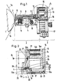
- the matrix print head In the writing position, the matrix print head is opposite a print abutment 1 or a recording medium 1a and an ink ribbon 1b.
- the platen 1 is designed as a round cylindrical platen.
- the matrix print head is divided into a print needle drive assembly 2 and a print needle adjustment assembly 3.
- the printing needle adjustment assembly 3 is used for the vertical height adjustment of a plurality of printing needles 4 arranged one above the other, a so-called needle gap, in order to write fine writing or fast writing (near letter quality / draft).
- the pressure needle adjusting assembly 3 is therefore only described in its essential components.
- the push pin adjustment assembly 3 includes a front housing 5 with an ink ribbon mask 6, in the inner cutout of which a vertically up and down adjustable guide mouthpiece 7 is provided, which is attached to a lever 8.
- the lever 8 is mounted on the front housing 5 by means of a leaf spring 9 and a screw 10, the leaf spring 9 forming a play-free joint.
- the lever 8 is adjusted via an electromagnet 11, the lever 8 being pulled in a controlled manner against the core (not shown in more detail) of the electromagnet 11 or being moved away therefrom.
- the adjustment of the lever 8 thus brings about an adjustment of the guide mouthpiece 7 with all the printing needles 4 in the vertical direction.
- the pressure needle adjusting assembly 3 is described in more detail in DE-A 3412 856.
- the printing needles 4 are moved in the direction of their longitudinal extension, ie in the printing direction.
- For these pressure movements are fastened on an end plate 12 in a base plate 13 in each case yoke body 14 for each individual printing needle 4.
- the outer legs 14a each carry an electromagnetic coil 14b.
- the yoke body 14, the base plate 13, the electromagnetic coils 14b form a magnetic block 15.
- a core bushing 16 is provided in the base plate 13.
- a centering bushing 19 (FIG. 2) extends into the core bushing 16.
- a screw 20 rests with its head 21 on a ring shoulder 16a of the core bushing 16 and pulls the centering bushing 19 with its ring shoulder 19a against the ring shoulder 16a, whereby the rear housing 17 is connected to the magnetic block 15 into one unit.
- a spring washer 22 is inserted under an outer ring shoulder 16b of the core bushing 16, which causes the core bushing 16 to work against the force of the screw 20.
- a plastic ring 23 forms a pivot bearing 24 for an armature 25, which with its front end 25a in the retracted position of the pressure needle 4 bears snugly against an annular disk-shaped stop 26.
- the annular disk-shaped stop 26 e.g. made of fluorine rubber
- the annular disk-shaped stop 26 is glued to the end face of the core sleeve 16 by means of a temperature-resistant adhesive 27.
- the printing needles 4 rest with their needle heads 4a against the front ends 25a of the anchors 25.
- the needle heads 4a are pressed by means of coil springs 28 against the stop 25, which are supported against an abutment 29 which is arranged concentrically with needle bores 17a in the rear housing 17.
- the position of the needle head 4a with respect to the armature 25 is determined by the distance "1".
- the pivot bearing 24 there are dimensions "a” for the distance from the rear end 25b of the armature 25 to the central axis 30, "b” from the pivot bearing 24 to the center of the needle head 4a when in contact with the front end 25a of the armature 25, “c "from the pivot bearing 24 to the rear end 25b of the armature 25.
- the dimensions a, b, c determine the energy and force ratios when the armature hits the stop 26 with more than 800 pulses per second.
- the effect of the layer thickness of the stop 26 and of the adhesive 27 is so damping during the impact that no rebound phenomena occur.
- the air gap 31 formed on a yoke leg 14a is set extremely precisely in the retracted position and is kept of the same size during a high number of pulses which are generated by energizing the electromagnetic coil 14b in order to generate 4 pressure points on the recording medium 1a with the printing needles.
- the design of the pressure needle adjustment assembly 3 is not of primary importance with regard to the energy consumption of the electromagnetic coils 14b, the armature 25 and the pressure needles 4, the design of the pressure needle adjustment assembly 3 nevertheless has a constructive effect on the design of the pressure needle drive assembly 2, with certain influences not being completely prevented are.
- the Drucknadelverstellbautechnik 3 can therefore be designed differently than shown and described in the drawing.
- the screw 20 is important with regard to the adjustment of the air gap 31, based on the spring washer 22.
- the needle adjusting assembly 3 it is of course possible to use the needle adjusting assembly 3 to be completely disregarded, ie to store the printing needles 4 in the usual manner within a combined housing, which is formed in one piece by the front housing 5 and the rear housing 17, in conventional guides up to the mouthpiece 7, this mouthpiece then not having to be adjustable.
Landscapes
- Impact Printers (AREA)
- Particle Formation And Scattering Control In Inkjet Printers (AREA)
- Magnetic Heads (AREA)
Priority Applications (1)
| Application Number | Priority Date | Filing Date | Title |
|---|---|---|---|
| AT86115255T ATE44910T1 (de) | 1985-11-16 | 1986-11-04 | Matrixdruckkopf. |
Applications Claiming Priority (2)
| Application Number | Priority Date | Filing Date | Title |
|---|---|---|---|
| DE19853540761 DE3540761A1 (de) | 1985-11-16 | 1985-11-16 | Matrixdruckkopf |
| DE3540761 | 1985-11-16 |
Publications (2)
| Publication Number | Publication Date |
|---|---|
| EP0223148A1 EP0223148A1 (de) | 1987-05-27 |
| EP0223148B1 true EP0223148B1 (de) | 1989-07-26 |
Family
ID=6286213
Family Applications (1)
| Application Number | Title | Priority Date | Filing Date |
|---|---|---|---|
| EP86115255A Expired EP0223148B1 (de) | 1985-11-16 | 1986-11-04 | Matrixdruckkopf |
Country Status (5)
| Country | Link |
|---|---|
| US (1) | US4822187A (enExample) |
| EP (1) | EP0223148B1 (enExample) |
| JP (1) | JPS62121066A (enExample) |
| AT (1) | ATE44910T1 (enExample) |
| DE (2) | DE3540761A1 (enExample) |
Cited By (1)
| Publication number | Priority date | Publication date | Assignee | Title |
|---|---|---|---|---|
| DE10257014B4 (de) * | 2002-12-06 | 2005-12-01 | Tally Computerdrucker Gmbh | Matrixnadeldruckkopf für Computerdrucker, insbesondere Druckkopf der Klappankerbauart |
Families Citing this family (5)
| Publication number | Priority date | Publication date | Assignee | Title |
|---|---|---|---|---|
| JPH0239947A (ja) * | 1988-07-29 | 1990-02-08 | Seikosha Co Ltd | 印字ヘッド |
| DE58908638D1 (de) * | 1989-09-18 | 1994-12-15 | Mannesmann Ag | Matrixnadeldruckkopf. |
| DE4020015C1 (enExample) * | 1990-06-20 | 1991-09-26 | Mannesmann Ag, 4000 Duesseldorf, De | |
| US5188466A (en) * | 1991-06-27 | 1993-02-23 | Mannesmann Aktiengesellschaft | Matrix pin print head with rebound control |
| JP2806414B2 (ja) * | 1992-08-18 | 1998-09-30 | 富士通株式会社 | 電気機械変換アクチュエータおよび印字ヘッド |
Family Cites Families (15)
| Publication number | Priority date | Publication date | Assignee | Title |
|---|---|---|---|---|
| US3345942A (en) * | 1966-06-14 | 1967-10-10 | Moreland Corp | Rubber covered roller |
| US3896918A (en) * | 1971-03-04 | 1975-07-29 | Winfried Schneider | Mosaic printing head with electromagnetically actuated needles with a common yoke for all electromagnets |
| FR2287340A1 (fr) * | 1974-10-08 | 1976-05-07 | Sagem | Perfectionnements apportes aux dispositifs ou tetes d'impression pour imprimantes ou analogues et procede de fabrication d'une telle tete d'impression |
| US3994218A (en) * | 1974-12-18 | 1976-11-30 | Teletype Corporation | Energy absorbing print hammer bumper with internal stabilizer |
| US4051941A (en) * | 1976-06-28 | 1977-10-04 | Xerox Corporation | Matrix print head with improved armature retainer |
| US4064799A (en) * | 1976-11-26 | 1977-12-27 | Teletype Corporation | Print hammer bumper exhibiting dual resiliency characteristics |
| US4140406A (en) * | 1977-06-13 | 1979-02-20 | Dataproducts | Dot matrix print head |
| DE2800218C2 (de) * | 1978-01-04 | 1980-02-07 | Triumph Werke Nuernberg Ag, 8500 Nuernberg | Nadeldruckkopf |
| US4230412A (en) * | 1978-03-17 | 1980-10-28 | Helmut Falk | Matrix print head assembly |
| US4298656A (en) * | 1980-03-28 | 1981-11-03 | Westinghouse Electric Corp. | Epoxy-elastomer low temperature curable, solventless, sprayable, stator winding adhesive-bracing compositions |
| DE3164230D1 (en) * | 1980-12-05 | 1984-07-19 | Tokyo Electric Co Ltd | Printing head of dot printer |
| IT1163942B (it) * | 1983-09-27 | 1987-04-08 | Honeywell Inf Systems | Gruppo elettromagnetico di stampa per stampante a mosaico |
| DE3412855A1 (de) * | 1984-04-03 | 1985-10-03 | Mannesmann AG, 4000 Düsseldorf | Matrixdruckkopf |
| US4647236A (en) * | 1984-12-07 | 1987-03-03 | Citizen Watch Co., Ltd. | Print head |
| DE8520709U1 (de) * | 1985-07-18 | 1985-10-10 | KSA Dichtsysteme GmbH & Co KG, 7143 Vaihingen | Flachdichtung |
-
1985
- 1985-11-16 DE DE19853540761 patent/DE3540761A1/de active Granted
-
1986
- 1986-11-04 DE DE8686115255T patent/DE3664596D1/de not_active Expired
- 1986-11-04 AT AT86115255T patent/ATE44910T1/de not_active IP Right Cessation
- 1986-11-04 EP EP86115255A patent/EP0223148B1/de not_active Expired
- 1986-11-14 JP JP61270025A patent/JPS62121066A/ja active Pending
- 1986-11-17 US US06/932,174 patent/US4822187A/en not_active Expired - Fee Related
Cited By (1)
| Publication number | Priority date | Publication date | Assignee | Title |
|---|---|---|---|---|
| DE10257014B4 (de) * | 2002-12-06 | 2005-12-01 | Tally Computerdrucker Gmbh | Matrixnadeldruckkopf für Computerdrucker, insbesondere Druckkopf der Klappankerbauart |
Also Published As
| Publication number | Publication date |
|---|---|
| US4822187A (en) | 1989-04-18 |
| ATE44910T1 (de) | 1989-08-15 |
| DE3664596D1 (en) | 1989-08-31 |
| JPS62121066A (ja) | 1987-06-02 |
| DE3540761A1 (de) | 1987-05-21 |
| EP0223148A1 (de) | 1987-05-27 |
| DE3540761C2 (enExample) | 1989-04-06 |
Similar Documents
| Publication | Publication Date | Title |
|---|---|---|
| US3831729A (en) | Solenoid having increased throw capability | |
| DE3031855A1 (de) | Druckkopf. | |
| EP0223148B1 (de) | Matrixdruckkopf | |
| DE2033378A1 (de) | Elektromagnetischer Antrieb zur Datenaufzeichnung | |
| DE2119415A1 (de) | Elektromagnetischer antrieb fuer die nadel eines nadeldruckers | |
| DE2800218C2 (de) | Nadeldruckkopf | |
| CA1108470A (en) | Hammer for impact printer | |
| DE2624809A1 (de) | Magnetspulen-baugruppe | |
| DE2629267A1 (de) | Antriebsvorrichtung fuer einen draht-matrixdrucker | |
| DE2800880B2 (de) | Drahtdrucker | |
| DE3412855C2 (enExample) | ||
| DE2807337A1 (de) | Matrixdruckerkopf | |
| DE3335415C2 (enExample) | ||
| DE2257246A1 (de) | Elektromagnetbaugruppe, z. b. fuer schnelldrucker | |
| DE3401420C2 (enExample) | ||
| DE2954141C2 (enExample) | ||
| EP0418433B1 (de) | Matrixnadeldruckkopf | |
| DE3305703A1 (de) | Druckkopf fuer einen punktdrucker | |
| DE2733312A1 (de) | Elektrodynamischer druckhammerantrieb | |
| DE3046105A1 (de) | Schnelldrucker | |
| DE2542077A1 (de) | Druckkopf | |
| DD142316A1 (de) | Druckmagneteinheit fuer den typendruck in seriendruckwerken | |
| DE3040399A1 (de) | Hochgeschwindigkeits-punktmatrix-drucker | |
| DE3420450C2 (enExample) | ||
| EP0314851B1 (de) | Matrixnadeldrucker mit verstellbarer Drucknadelführung |
Legal Events
| Date | Code | Title | Description |
|---|---|---|---|
| PUAI | Public reference made under article 153(3) epc to a published international application that has entered the european phase |
Free format text: ORIGINAL CODE: 0009012 |
|
| AK | Designated contracting states |
Kind code of ref document: A1 Designated state(s): AT BE CH DE FR GB IT LI NL |
|
| 17P | Request for examination filed |
Effective date: 19870624 |
|
| 17Q | First examination report despatched |
Effective date: 19890113 |
|
| GRAA | (expected) grant |
Free format text: ORIGINAL CODE: 0009210 |
|
| AK | Designated contracting states |
Kind code of ref document: B1 Designated state(s): AT BE CH DE FR GB IT LI NL |
|
| REF | Corresponds to: |
Ref document number: 44910 Country of ref document: AT Date of ref document: 19890815 Kind code of ref document: T |
|
| REF | Corresponds to: |
Ref document number: 3664596 Country of ref document: DE Date of ref document: 19890831 |
|
| GBT | Gb: translation of ep patent filed (gb section 77(6)(a)/1977) | ||
| ET | Fr: translation filed | ||
| ITF | It: translation for a ep patent filed | ||
| PLBI | Opposition filed |
Free format text: ORIGINAL CODE: 0009260 |
|
| 26 | Opposition filed |
Opponent name: NIXDORF COMPUTER AG Effective date: 19900426 |
|
| NLR1 | Nl: opposition has been filed with the epo |
Opponent name: NIXDORF COMPUTER AG. |
|
| PGFP | Annual fee paid to national office [announced via postgrant information from national office to epo] |
Ref country code: CH Payment date: 19901018 Year of fee payment: 5 Ref country code: BE Payment date: 19901018 Year of fee payment: 5 |
|
| PGFP | Annual fee paid to national office [announced via postgrant information from national office to epo] |
Ref country code: AT Payment date: 19901030 Year of fee payment: 5 |
|
| PGFP | Annual fee paid to national office [announced via postgrant information from national office to epo] |
Ref country code: NL Payment date: 19901130 Year of fee payment: 5 |
|
| PLAB | Opposition data, opponent's data or that of the opponent's representative modified |
Free format text: ORIGINAL CODE: 0009299OPPO |
|
| R26 | Opposition filed (corrected) |
Opponent name: SIEMENS NIXDORF INFORMATIONSSYSTEME AKTIENGESELLSC Effective date: 19900426 |
|
| PG25 | Lapsed in a contracting state [announced via postgrant information from national office to epo] |
Ref country code: AT Effective date: 19911104 |
|
| ITTA | It: last paid annual fee | ||
| PG25 | Lapsed in a contracting state [announced via postgrant information from national office to epo] |
Ref country code: LI Effective date: 19911130 Ref country code: CH Effective date: 19911130 Ref country code: BE Effective date: 19911130 |
|
| BERE | Be: lapsed |
Owner name: MANNESMANN A.G. Effective date: 19911130 |
|
| PG25 | Lapsed in a contracting state [announced via postgrant information from national office to epo] |
Ref country code: NL Effective date: 19920601 |
|
| NLV4 | Nl: lapsed or anulled due to non-payment of the annual fee | ||
| REG | Reference to a national code |
Ref country code: CH Ref legal event code: PL |
|
| PLBN | Opposition rejected |
Free format text: ORIGINAL CODE: 0009273 |
|
| STAA | Information on the status of an ep patent application or granted ep patent |
Free format text: STATUS: OPPOSITION REJECTED |
|
| 27O | Opposition rejected |
Effective date: 19940307 |
|
| PGFP | Annual fee paid to national office [announced via postgrant information from national office to epo] |
Ref country code: FR Payment date: 19941012 Year of fee payment: 9 |
|
| PGFP | Annual fee paid to national office [announced via postgrant information from national office to epo] |
Ref country code: GB Payment date: 19941013 Year of fee payment: 9 |
|
| PG25 | Lapsed in a contracting state [announced via postgrant information from national office to epo] |
Ref country code: GB Effective date: 19951104 |
|
| GBPC | Gb: european patent ceased through non-payment of renewal fee |
Effective date: 19951104 |
|
| PG25 | Lapsed in a contracting state [announced via postgrant information from national office to epo] |
Ref country code: FR Effective date: 19960731 |
|
| REG | Reference to a national code |
Ref country code: FR Ref legal event code: ST |
|
| PGFP | Annual fee paid to national office [announced via postgrant information from national office to epo] |
Ref country code: DE Payment date: 20010104 Year of fee payment: 15 |
|
| PG25 | Lapsed in a contracting state [announced via postgrant information from national office to epo] |
Ref country code: DE Free format text: LAPSE BECAUSE OF NON-PAYMENT OF DUE FEES Effective date: 20020702 |
|
| APAH | Appeal reference modified |
Free format text: ORIGINAL CODE: EPIDOSCREFNO |
|
| PG25 | Lapsed in a contracting state [announced via postgrant information from national office to epo] |
Ref country code: IT Free format text: LAPSE BECAUSE OF NON-PAYMENT OF DUE FEES Effective date: 20051104 |
|
| PLAB | Opposition data, opponent's data or that of the opponent's representative modified |
Free format text: ORIGINAL CODE: 0009299OPPO |