EP0222698B1 - Bohrhammer mit pneumatisch angetriebenem Schlagkolben - Google Patents
Bohrhammer mit pneumatisch angetriebenem Schlagkolben Download PDFInfo
- Publication number
- EP0222698B1 EP0222698B1 EP86810462A EP86810462A EP0222698B1 EP 0222698 B1 EP0222698 B1 EP 0222698B1 EP 86810462 A EP86810462 A EP 86810462A EP 86810462 A EP86810462 A EP 86810462A EP 0222698 B1 EP0222698 B1 EP 0222698B1
- Authority
- EP
- European Patent Office
- Prior art keywords
- piston
- pistons
- air cushion
- closure part
- cylinder
- Prior art date
- Legal status (The legal status is an assumption and is not a legal conclusion. Google has not performed a legal analysis and makes no representation as to the accuracy of the status listed.)
- Expired
Links
- 230000003116 impacting effect Effects 0.000 title 1
- 238000009527 percussion Methods 0.000 claims abstract description 16
- 238000002844 melting Methods 0.000 claims description 9
- 230000008018 melting Effects 0.000 claims description 9
- 229910001128 Sn alloy Inorganic materials 0.000 claims description 4
- 239000000463 material Substances 0.000 claims description 4
- 239000000155 melt Substances 0.000 abstract description 2
- 238000007789 sealing Methods 0.000 description 11
- 238000005553 drilling Methods 0.000 description 6
- 230000000694 effects Effects 0.000 description 2
- 238000012423 maintenance Methods 0.000 description 2
- XAGFODPZIPBFFR-UHFFFAOYSA-N aluminium Chemical compound [Al] XAGFODPZIPBFFR-UHFFFAOYSA-N 0.000 description 1
- 229910052782 aluminium Inorganic materials 0.000 description 1
- 238000005266 casting Methods 0.000 description 1
- 230000007423 decrease Effects 0.000 description 1
- 238000013461 design Methods 0.000 description 1
- 238000011161 development Methods 0.000 description 1
- 239000000314 lubricant Substances 0.000 description 1
- 230000001050 lubricating effect Effects 0.000 description 1
- 238000005461 lubrication Methods 0.000 description 1
- 230000000149 penetrating effect Effects 0.000 description 1
- 230000000737 periodic effect Effects 0.000 description 1
- 230000002265 prevention Effects 0.000 description 1
- 229910000679 solder Inorganic materials 0.000 description 1
- 238000013022 venting Methods 0.000 description 1
Images
Classifications
-
- B—PERFORMING OPERATIONS; TRANSPORTING
- B25—HAND TOOLS; PORTABLE POWER-DRIVEN TOOLS; MANIPULATORS
- B25D—PERCUSSIVE TOOLS
- B25D16/00—Portable percussive machines with superimposed rotation, the rotational movement of the output shaft of a motor being modified to generate axial impacts on the tool bit
-
- B—PERFORMING OPERATIONS; TRANSPORTING
- B25—HAND TOOLS; PORTABLE POWER-DRIVEN TOOLS; MANIPULATORS
- B25D—PERCUSSIVE TOOLS
- B25D17/00—Details of, or accessories for, portable power-driven percussive tools
- B25D17/06—Hammer pistons; Anvils ; Guide-sleeves for pistons
-
- B—PERFORMING OPERATIONS; TRANSPORTING
- B25—HAND TOOLS; PORTABLE POWER-DRIVEN TOOLS; MANIPULATORS
- B25D—PERCUSSIVE TOOLS
- B25D2211/00—Details of portable percussive tools with electromotor or other motor drive
- B25D2211/06—Means for driving the impulse member
- B25D2211/068—Crank-actuated impulse-driving mechanisms
Definitions
- the invention relates to a rotary hammer with a cylinder for guiding a drive piston which can be moved to and fro by motor and a percussion piston with the interposition of an air cushion, at least one of the two pistons having a connecting channel leading outwards from the air cushion space.
- leakage losses are the result of inadequate sealing between the pistons and the cylinder, caused in particular by wear on sealing elements on the piston side.
- poor lubrication and failure of any heat-sensitive sealing elements promote such leakage losses.
- a disadvantage of this design is the risk that damage to device parts can already occur due to the impact of the percussion piston required to break out the base part.
- the invention has for its object to provide a hammer drill with a pneumatic hammer mechanism, in which a prevention of damage resulting from leakage of the air cushion is ensured.
- the object is achieved in that the connecting channel is closed by a closure part made of material with a low melting point.
- the invention takes advantage of the knowledge that, as a result of the leakage losses, the power on the percussion piston decreases. Since the power delivered by the engine to the drive piston remains unchanged, the thermal power of the striking mechanism increases with increasing leakage losses, which increases the overall operating temperature.
- the connecting channel is kept closed by the closure part. If, for example, a temperature that is 20% higher than the normal operating temperature occurs, the closure melts. This opens the connection channel and the air cushion breaks down.
- the coefficient of thermal expansion of the closure part can be approximately equal to or greater than that of the pistons.
- the percussion piston which is pneumatically decoupled from the drive piston after the closure part has melted, assumes a rest position, regardless of any further reciprocation of the drive piston.
- the operator can suddenly discontinue the delivery of the punch. As a result, he will take the device out of operation. This prevents consequential damage to the drive elements for the striking mechanism or other device parts.
- the device By replacing the locking part and carrying out the necessary maintenance measures, such as replacing the sealing elements and lubricating the striking mechanism, the device can be brought back into operational condition without damage.
- the connecting channel is preferably designed as a bore penetrating the pistons in the axial direction.
- the connecting channel expediently runs concentrically or - formed by several bores - symmetrically to the longitudinal axis of the pistons.
- the closure part is advantageously arranged at the end of the piston facing the air cushion. This location of the pistons is in the spatial vicinity of the locations of the device that are relevant for increased temperature, so that the closure part is directly exposed to the effects of heat. This ensures a sensitive and precise reaction of the closure part even at different ambient temperatures of the device.
- closure part is positively held in the connecting channel by means of undercuts.
- the back stitches can be, for example, closed circumferential grooves or thread grooves.
- the closure part extends in the form of a plug, for example, over part of the longitudinal extent of the bore. It is possible to insert the closure part into the bore as a fully formed plug or in the casting process.
- the closure part is arranged on the drive piston. This is particularly advantageous for maintaining a good fit of the closure part in the bore. While the percussion piston is constantly exposed to abrupt decelerations due to its impact on the tool, which could lead to a locking part mounted therein being displaced, the drive piston can be moved back and forth, for example, by a crank mechanism without abrupt deceleration.
- the closure part preferably consists of a tin alloy.
- This material is particularly suitable because its coefficient of thermal expansion corresponds approximately to the coefficient of thermal expansion of the drive piston, which is preferably made of aluminum.
- Suitable tin alloys are especially soft solders according to DIN 1707 with selectable melting points from 150 ° to 250 ° C.
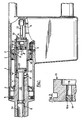
- a housing 1 consists of a housing 1, in which a cylinder 4 is rotatably supported by a front ball bearing 2 and a rear roller bearing 3.
- the cylinder 4 is designed as a receptacle for an indicated drilling tool 5.
- the latter has driving grooves 5a for engaging locking elements, not shown.
- a sealing ring 6 supported on the housing side is intended to prevent dirt from entering the device and the escape of lubricants.
- a bevel gear 7 is arranged on the cylinder 4 and is connected to the cylinder 4 in a rotationally fixed manner by a locking pin 8.
- the bevel gear 7 and the cylinder 4 are driven in rotation by a motor-driven bevel pinion 9.
- An eccentric shaft 11 is also driven by the motor (not shown), which moves a drive piston mounted in the cylinder 4, generally designated 13, via a connecting rod 12 .
- the drive piston 13 is penetrated concentrically to its longitudinal axis by a bore 16 which serves as a connecting channel between the cylinder space adjoining the drive piston 13 in the drilling direction and the recess which is open to the outside.
- the drive piston 13 also carries an annular sealing element 19 which interacts with the cylinder 4.
- closure part 17 engages positively in the undercuts 16a in the form of thread grooves.
- an impact piston In the cylinder 4 in front of the drive piston 13 there is also an impact piston, generally designated 21, which is displaceably mounted. This has a shaft 22 for transmitting impact pulses to the drilling tool 5 and a head 23 on the rear. The head 23, like the drive piston 13, is provided with a sealing element 24.
- the percussion piston 21 is likewise set in a reciprocating movement by the air cushion standing between the two pistons in the cylinder 4 in a phase-shifted manner.
- the cylinder 4 has blow-off bores 4a on the front side.
- a compensating bore 4b is provided in the cylinder 4, which ensures the periodic build-up of the air cushion.
- the melting temperature of the closure part 17 is at the elevated temperature level that is reached before the pistons 13, 21 collide.
- the melting of the closure part 17 leads to the venting of the cylinder space located between the pistons 13, 21 to the outside via the bore 16.
- the percussion piston 21 is thus no longer activated by the drive piston 13, which is moved back and forth by motor, and remains in an end position on the drilling direction side. The operator notices that the punch has not been delivered and will then take the device out of operation. Costly consequential damage, such as might occur if the pistons 13, 21 collide, is reliably prevented in this way.
- the hammer drill described is suitable for rotating and striking drive of the drilling tool 5.
- the arrangement according to the invention can also be used in devices which only impart impact energy to a tool.
Landscapes
- Engineering & Computer Science (AREA)
- Mechanical Engineering (AREA)
- Percussive Tools And Related Accessories (AREA)
- Supply Devices, Intensifiers, Converters, And Telemotors (AREA)
- Earth Drilling (AREA)
- Drilling And Boring (AREA)
Description
- Die Erfindung betrifft einen Bohrhammer mit einem Zylinder zur Führung eines motorisch hin und her verschiebbaren Antriebskolbens und eines Schlagkolbens unter Zwischenschaltung eines Luftpolsters, wobei wenigstens einer der beiden Kolben einen vom Luftpolsterraum nach aussen führenden Verbindungskanal aufweist.
- Bei bekannten Bohrhämmern mit einem sogenannten pneumatischen Schlagwerk, das über einen in einem Zylinder motorisch hin und her bewegten Antriebskolben und über einen Schlagkolben verfügt, der unter Zwischenschaltung eines Luftpolsters ebenso hin und her bewegt wird, kann sich als Folge zunehmender Leckverluste ein ausreichendes Luftpolster nicht mehr aufbauen, so dass durch Zusammenschlagen der Kolben Schäden am Schlagwerk und darüberhinaus an den Antriebsorganen für das Schlagwerk sowie an weiteren Geräteteilen auftreten können.
- Die Leckverluste sind die Folge mangelhafter Dichtung zwischen den Kolben und dem Zylinder, hervorgerufen insbesondere durch Verschleiss kolbenseitiger Dichtelemente. Zudem fördern mangelhafte Schmierung und Ausfall von gegebenenfalls wärmeempfindlichen Dichtelementen solche Leckverluste.
- Zur Vermeidung über das Schlagwerk hinausgehender kostspieliger Schäden als Folge von Leckverlusten ist bei einem bekannten Bohrhammer (DE-OS 2 729 596) am Antriebskolben ein Bodenteil vorgesehen, das beim Aufprallen des Schlagkolbens ausbricht. Dadurch wird der zwischen den beiden Kolben liegende Raum nach aussen entlüftet, so dass der Schlagkolben mangels eines Luftpolsters nicht mehr hin und her bewegt wird.
- Ein Nachteil dieser Ausbildung besteht in der Gefahr, dass durch das zum Ausbrechen des Bodenteiles erforderliche Aufprallen des Schlagkolbens bereits Schäden an Geräteteilen auftreten können.
- Der Erfindung liegt die Aufgabe zugrunde, einen Bohrhammer mit pneumatischem Schlagwerk zu schaffen, bei dem eine Verhinderung von aus Leckverlusten des Luftpolsters resultierenden Schäden gewährleistet wird.
- Erfindungsgemäss wird die Aufgabe dadurch gelöst, dass der Verbindungskanal von einem Verschlussteil aus Material mit niedrigem Schmelzpunkt verschlossen ist.
- Die Erfindung macht sich die Erkenntnis zunutze, dass zufolge der Leckverluste die Leistung am Schlagkolben abnimmt. Da die vom Motor an den Antriebskolben abgegebene Leistung unverändert bleibt, steigt die Wärmeleistung des Schlagwerkes zunehmend mit grösser werdenden Leckverlusten, wodurch sich die Betriebstemperatur insgesamt erhöht.
- Bei regulärer Betriebstemperatur oder unter dieser liegender Anlauftemperatur wird der Verbindungskanal vom Verschlussteil geschlossen gehalten. Tritt gegenüber der regulären Betriebstemperatur eine beispielsweise um 20% erhöhte Temperatur auf, schmilzt das Verschlussteil. Dadurch öffnet sich der Verbindungskanal und das Luftpolster bricht zusammen.
- Bei der Materialwahl ist zu beachten, dass das Schmelzen eintritt, ausreichend bevor es zu einem Zusammenprallen der Kolben kommt. Zudem ist durch geeignete Wahl des Wärmeausdehnungskoeffizienten die ausreichende Abdichtung vor Eintritt des Schmelzens sicherzustellen, d.h. der Wärmeausdehnungskoeffizient des Verschlussteiles kann gegenüber jenem der Kolben etwa gleich oder grösser sein. Der nach dem Schmelzen des Verschlussteiles vom Antriebskolben pneumatisch entkoppelte Schlagkolben nimmt, unabhängig von weiterer Hin- und Herbewegung des Antriebskolbens, Ruheposition ein.
- Für den Handhabenden ist als Folge des Schmelzens des Verschlussteiles ein plötzlicher Abbruch der Schlagabgabe feststellbar. Folglich wird er das Gerat ausser Betrieb nehmen. Folgeschäden an den Antriebsorganen für das Schlagwerk oder an weiteren Geräteteilen werden somit unterbunden. Durch Ersetzen des Verschlussteiles und Ausführung der erforderlichen Wartungsmassnahmen, wie Austausch der Dichtelemente und Schmieren des Schlagwerkes, kann das Gerät ohne Schaden wieder in betriebsbereiten Zustand gebracht werden.
- Vorzugsweise ist der Verbindungskanal als eine die Kolben in Achsrichtung durchsetzende Bohrung ausgebildet. Um eine gleichmässige Gewichtsverteilung der Kolben zu erzielen, verläuft der Verbindungskanal zweckmässig konzentrisch oder - gebildet durch mehrere Bohrungen - symmetrisch zur Längsachse der Kolben.
- Mit Vorteil ist das Verschlussteil an dem zum Luftpolster weisenden Ende der Kolben angeordnet. Diese Stelle der Kolben liegt im räumlichen Nahbereich der für erhöhte Temperatur massgeblichen Stellen des Gerätes, so dass das Verschlussteil der Wärmeeinwirkung direkt ausgesetzt ist. Damit ist ein sensibles und präzises Reagieren des Verschlussteiles auch bei unterschiedlichen Umgebungstemperaturen des Gerätes gewährleistet.
- Ein im besonderen erschütterungsfester Sitz des Verschlussteiles in der Bohrung wird in Weiterbildung der Erfindung erreicht, indem das Verschlussteil mittels Hinterstichen im Verbindungskanal formschlüssig gehaltert wird. Bei den Hinterstichen kann es sich beispielsweise um in sich geschlossene umlaufende Rillen oder um Gewinderillen handeln. Das Verschlussteil erstreckt sich in Form eines Pfropfens beispielsweise über einen Teil der Längserstreckung der Bohrung. Es ist möglich, das Verschlussteil als fertig geformter Pfropfen oder im Giessverfahren in die Bohrung einzubringen.
- Nach einem weiteren Vorschlag der Erfindung ist das Verschlussteil am Antriebskolben angeordnet. Dies ist insbesondere für die Beibehaltung eines guten Sitzes des Verschlussteils in der Bohrung von Vorteil. Während der Schlagkolben durch dessen Aufprallen am Werkzeug fortwährend abrupten Abbremsungen ausgesetzt ist, was zu einem Verschieben eines hierin gelagerten Verschlussteiles führen könnte, lässt sich der Antriebskolben ohne abrupte Abbremsung beispielsweise von einem Kurbeltrieb hin und her verschieben.
- Vorzugsweise besteht das Verschlussteil aus einer Zinnlegierung. Dieses Material eignet sich im besonderen, da dessen Wärmeausdehnungskoeffizient etwa dem Wärmeausdehnungskoeffizienten des vorzugsweise aus Aluminium bestehenden Antriebskolbens entspricht. Als Zinnlegierungen eignen sich im besonderen Weichlote nach DIN 1707 mit wählbaren Schmelzpunkten von 150° bis 250°C.
- Die Erfindung wird nachstehend anhand einer Zeichnung, die ein Ausführungsbeispiel wiedergibt, näher erläutert. Es zeigen:
- Fig. 1 einen Bohrhammer, teilweise im Längsschnitt;
- Fig. 2 einen Ausschnitt II aus Fig. 1 in vergrösserter Darstellung.
- Der Bohrhammer nach Fig. 1 besteht aus einem Gehäuse 1, in welchem durch ein vorderseitiges Kugellager 2 und ein rückseitiges Rollenlager 3 ein Zylinder 4 drehbar gelagert ist. Im vorderen Bereich ist der Zylinder 4 als Aufnahme für ein andeutungsweise erkennbares Bohrwerkzeug 5 ausgebildet. Letzteres weist Mitnahmenuten 5a zum Eingriff nicht dargestellter Verriegelungselemente auf. Ein gehäuseseitig abgestützter Dichtring 6 soll das Eindringen von Schmutz in das Gerät und das Austreten von Schmierstoffen unterbinden.
- Auf dem Zylinder 4 ist ein Kegelrad 7 angeordnet, das durch einen Sicherungsstift 8 mit dem Zylinder 4 drehfest verbunden ist. Der Drehantrieb des Kegelrades 7 bzw. des Zylinders 4 erfolgt durch ein motorisch angetriebenes Kegelritzel 9. Ferner wird vom nicht gezeigten Motor auch eine Exzenterwelle 11 angetrieben, die über einen Pleuel 12 einen im Zylinder 4 gelagerten, insgesamt mit 13 bezeichneten Antriebskolben hin und her bewegt. Zur Kupplung des Pleueles 12 mit dem Antriebskolben 13 sind die genannten Teile von einem Bolzen 14 durchquert, wobei der vom Bolzen 14 durchquerte Endabschnitt des Pleueles 12 in eine taschenartige Vertiefung 15 des Antriebskolbens 13 eingreift.
- Der Antriebskolben 13 ist konzentrisch zu dessen Längsachse von einer Bohrung 16 durchsetzt, die als Verbindungskanal zwischen dem in Bohrrichtung an den Antriebskolben 13 anschliessenden Zylinderraum und der nach aussen offenen Vertiefung dient. Im bohrrichtungsseitigen Endabschnitt der Bohrung 16 ist lagefest ein pfropfenförmiges Verschlussteil 17 aus einer Zinnlegierung, die sich durch niedrigen Schmelzpunkt auszeichnet, angeordnet. Der Antriebskolben 13 trägt ferner in einem umlaufenden Einstich 18 ein mit dem Zylinder 4 zusammenwirkendes ringförmiges Dichtelement 19.
- Wie die Fig. 2 verdeutlicht, greift das Verschlussteil 17 formschlüssig in Hinterstiche 16a in Form von Gewinderillen ein.
- Im Zylinder 4 ist in Bohrrichtung vor dem Antriebskolben 13 auch ein insgesamt mit 21 bezeichneter Schlagkolben verschiebbar gelagert. Dieser weist einen Schaft 22 zur Übertragung von Schlagimpulsen an das Bohrwerkzeug 5 sowie rückseitig einen Kopf 23 auf. Der Kopf 23 ist ebenso wie der Antriebskolben 13 mit einem Dichtelement 24 versehen.
- Durch die Hin- und Herbewegung des Antriebskolbens 13 wird der Schlagkolben 21 von dem zwischen den beiden Kolben im Zylinder 4 stehenden Luftpolster entsprechend phasenverschoben ebenso in hin- und hergehende Bewegung versetzt. Um dabei das Vorlaufen des Schlagkolbens 21 in die gezeigte schlagabgebende Stellung nicht zu hemmen, weist der Zylinder 4 vorderseitig Abblasbohrungen 4a auf. Des weiteren ist im Zylinder 4 eine Ausgleichsbohrung 4b vorgesehen, welche den periodischen Aufbau des Luftpolsters sicherstellt. Mit zunehmender Einsatzdauer des Bohrhammers lasst die Wirkung der Dichtelemente 19, 24 nach, was zur Folge hat, dass Leckverluste auftreten und folglich der Antriebskolben 13 und der Schlagkolben 21 bei der aufeinander zugerichteten Hubbewegung immer näher aneinander gelangen.
- Gegenüber der regulären Betriebstemperatur kommt es aufgrund der Leckverluste zu einer sich zunehmend erhöhenden Temperatur. Die Schmelztemperatur des Verschlussteiles 17 liegt auf jenem erhöhten Temperaturniveau, das erreicht wird, bevor ein Aufeinanderprallen der Kolben 13, 21 erfolgt. Das Schmelzen des Verschlussteiles 17 führt zum Entlüften des zwischen den Kolben 13, 21 liegenden Zylinderraumes über die Bohrung 16 nach aussen. Der Schlagkolben 21 wird somit von dem motorisch weiter hin und her bewegten Antriebskolben 13 nicht mehr aktiviert und bleibt in einer bohrrichtungsseitigen Endstellung stehen. Der Handhabende bemerkt ein Ausbleiben der Schlagabgabe und wird daraufhin das Gerät ausser Betrieb nehmen. Kostspielige Folgeschäden, wie sie bei einem Zusammenprallen der Kolben 13, 21 entstehen könnten, werden auf diese Weise zuverlässig unterbunden.
- Zur neuerlichen Inbetriebnahme des Bohrhammers ist die erforderliche Wartung durchzuführen, wobei ein neues Verschlussteil 17 und neue Dichtelemente 19, 24 eingebracht werden.
- Der beschriebene Bohrhammer ist für drehenden und schlagenden Antrieb des Bohrwerkzeuges 5 geeignet. Selbstverständlich ist die erfindungsgemässe Anordnung aber auch bei Geräten einsetzbar, die einem Werkzeug nur Schlagenergie vermitteln.
Claims (6)
Priority Applications (1)
| Application Number | Priority Date | Filing Date | Title |
|---|---|---|---|
| AT86810462T ATE42490T1 (de) | 1985-11-02 | 1986-10-20 | Bohrhammer mit pneumatisch angetriebenem schlagkolben. |
Applications Claiming Priority (2)
| Application Number | Priority Date | Filing Date | Title |
|---|---|---|---|
| DE3539030 | 1985-11-02 | ||
| DE19853539030 DE3539030A1 (de) | 1985-11-02 | 1985-11-02 | Bohrhammer mit pneumatisch angetriebenem schlagkolben |
Publications (2)
| Publication Number | Publication Date |
|---|---|
| EP0222698A1 EP0222698A1 (de) | 1987-05-20 |
| EP0222698B1 true EP0222698B1 (de) | 1989-04-26 |
Family
ID=6285104
Family Applications (1)
| Application Number | Title | Priority Date | Filing Date |
|---|---|---|---|
| EP86810462A Expired EP0222698B1 (de) | 1985-11-02 | 1986-10-20 | Bohrhammer mit pneumatisch angetriebenem Schlagkolben |
Country Status (6)
| Country | Link |
|---|---|
| US (1) | US4732219A (de) |
| EP (1) | EP0222698B1 (de) |
| JP (1) | JPS62107985A (de) |
| AT (1) | ATE42490T1 (de) |
| AU (1) | AU583952B2 (de) |
| DE (2) | DE3539030A1 (de) |
Families Citing this family (10)
| Publication number | Priority date | Publication date | Assignee | Title |
|---|---|---|---|---|
| ZA908924B (en) * | 1990-01-15 | 1991-08-28 | Sulzer Ag | A percussion device |
| JP3459493B2 (ja) * | 1995-05-25 | 2003-10-20 | 株式会社マキタ | 打撃工具 |
| DE19828423C2 (de) * | 1998-06-25 | 2000-05-18 | Wacker Werke Kg | Antriebskolben für ein Luftfederschlagwerk |
| DE10034742A1 (de) * | 2000-07-17 | 2002-01-31 | Hilti Ag | Werkzeug mit zugeordnetem Schlagwerkzeug |
| EP1584420B1 (de) * | 2004-04-07 | 2014-06-11 | HILTI Aktiengesellschaft | Bohr- und/oder Meisselhammer mit elektropneumatischem Schlagwerk und einer Vorrichtung zur variablen Einstellung der Schlagenergie |
| JP4916872B2 (ja) * | 2006-12-26 | 2012-04-18 | 株式会社マキタ | 打撃工具 |
| JP2012196728A (ja) * | 2011-03-18 | 2012-10-18 | Makita Corp | 打撃工具 |
| JP6026861B2 (ja) * | 2012-11-19 | 2016-11-16 | 株式会社マキタ | 打撃工具 |
| US9573262B2 (en) | 2012-11-19 | 2017-02-21 | Makita Corporation | Impact tool |
| EP3181302A1 (de) | 2015-12-14 | 2017-06-21 | HILTI Aktiengesellschaft | Handwerkzeugmaschine |
Family Cites Families (4)
| Publication number | Priority date | Publication date | Assignee | Title |
|---|---|---|---|---|
| US3688848A (en) * | 1971-03-15 | 1972-09-05 | Black & Decker Mfg Co | Air spring bleed assembly |
| DE2729596A1 (de) * | 1977-06-30 | 1979-01-11 | Hilti Ag | Bohrhammer mit pneumatisch angetriebenem schlagkolben |
| GB2052346B (en) * | 1979-06-18 | 1983-02-02 | Kango Electric Hammers Ltd | Rotary hammer drills |
| US4336847A (en) * | 1980-06-27 | 1982-06-29 | Hitachi Koki Company, Limited | Percussion drill |
-
1985
- 1985-11-02 DE DE19853539030 patent/DE3539030A1/de not_active Withdrawn
-
1986
- 1986-10-20 DE DE8686810462T patent/DE3662983D1/de not_active Expired
- 1986-10-20 EP EP86810462A patent/EP0222698B1/de not_active Expired
- 1986-10-20 AT AT86810462T patent/ATE42490T1/de not_active IP Right Cessation
- 1986-10-28 JP JP61254815A patent/JPS62107985A/ja active Granted
- 1986-10-31 AU AU64618/86A patent/AU583952B2/en not_active Ceased
- 1986-11-03 US US06/926,712 patent/US4732219A/en not_active Expired - Fee Related
Also Published As
| Publication number | Publication date |
|---|---|
| DE3662983D1 (en) | 1989-06-01 |
| JPH0553584B2 (de) | 1993-08-10 |
| US4732219A (en) | 1988-03-22 |
| AU583952B2 (en) | 1989-05-11 |
| EP0222698A1 (de) | 1987-05-20 |
| DE3539030A1 (de) | 1987-05-07 |
| ATE42490T1 (de) | 1989-05-15 |
| JPS62107985A (ja) | 1987-05-19 |
| AU6461886A (en) | 1987-05-07 |
Similar Documents
| Publication | Publication Date | Title |
|---|---|---|
| DE19815650B4 (de) | Drehbohrhammer | |
| EP0222698B1 (de) | Bohrhammer mit pneumatisch angetriebenem Schlagkolben | |
| EP0349742B1 (de) | Kraftbetätigtes Spannfutter | |
| DE19525431C2 (de) | Presse zum Stanzen von Löchern in ein Werkstück | |
| DE1297559B (de) | Kraftbetaetigtes Schlagwerkzeug | |
| DE69016742T2 (de) | Schlagmotor. | |
| DE2938513C2 (de) | ||
| DE2023913B2 (de) | Elektropneumatischer Bohrhammer | |
| DE69021008T2 (de) | Hammermaschine. | |
| EP0589337B1 (de) | Handwerkzeugmaschine, insbesondere Bohrhammer | |
| DE2343014B2 (de) | Pneumatischer Bohrhammer | |
| EP1261459B1 (de) | Luftfederschlagwerk mit hohlem schlagkolben | |
| DE2804388A1 (de) | Hydraulischer gesteinsbohrer | |
| DE1552498C2 (de) | Vorrichtung zum Zuführen von Kühlflüssigkeit zu den Schneidflächen eines in einer Bohrung rotierenden Bohrwerkzeugs | |
| EP0266305B1 (de) | Bohrhammer mit Schlagwerk | |
| DE69011469T2 (de) | Tragbare Schlagmaschine. | |
| DE2335924A1 (de) | Handwerkzeugmaschine mit betriebszeitanzeigevorrichtung | |
| DE9405697U1 (de) | Kraftschrauber | |
| EP0768150B1 (de) | Werkzeughalter | |
| DE3936849A1 (de) | Elektrisch angetriebene handwerkzeugmaschine | |
| EP0473968B1 (de) | Hydraulisch betriebene Schlagdrehbohrvorrichtung, insbesondere zum Ankerlochbohren | |
| DE2605998C3 (de) | Bohrhammer mit in einem Zylinder untergebrachten Antriebs- und Schlagelementen | |
| DE3526996C2 (de) | Bohr- und Meisselhammer mit Entlüftung | |
| DE4127085C2 (de) | Pneumatisches Schraubgerät | |
| EP1364109A1 (de) | Durch einen verbrennungsmotor angetriebenes arbeitsgerät mit ölschmierung |
Legal Events
| Date | Code | Title | Description |
|---|---|---|---|
| PUAI | Public reference made under article 153(3) epc to a published international application that has entered the european phase |
Free format text: ORIGINAL CODE: 0009012 |
|
| AK | Designated contracting states |
Kind code of ref document: A1 Designated state(s): AT BE CH DE FR GB IT LI NL SE |
|
| 17P | Request for examination filed |
Effective date: 19870615 |
|
| 17Q | First examination report despatched |
Effective date: 19881003 |
|
| GRAA | (expected) grant |
Free format text: ORIGINAL CODE: 0009210 |
|
| AK | Designated contracting states |
Kind code of ref document: B1 Designated state(s): AT BE CH DE FR GB IT LI NL SE |
|
| REF | Corresponds to: |
Ref document number: 42490 Country of ref document: AT Date of ref document: 19890515 Kind code of ref document: T |
|
| ITF | It: translation for a ep patent filed | ||
| REF | Corresponds to: |
Ref document number: 3662983 Country of ref document: DE Date of ref document: 19890601 |
|
| ET | Fr: translation filed | ||
| GBT | Gb: translation of ep patent filed (gb section 77(6)(a)/1977) | ||
| PLBE | No opposition filed within time limit |
Free format text: ORIGINAL CODE: 0009261 |
|
| STAA | Information on the status of an ep patent application or granted ep patent |
Free format text: STATUS: NO OPPOSITION FILED WITHIN TIME LIMIT |
|
| 26N | No opposition filed | ||
| ITTA | It: last paid annual fee | ||
| PGFP | Annual fee paid to national office [announced via postgrant information from national office to epo] |
Ref country code: BE Payment date: 19931028 Year of fee payment: 8 |
|
| PGFP | Annual fee paid to national office [announced via postgrant information from national office to epo] |
Ref country code: SE Payment date: 19940526 Year of fee payment: 9 |
|
| PGFP | Annual fee paid to national office [announced via postgrant information from national office to epo] |
Ref country code: DE Payment date: 19940928 Year of fee payment: 9 |
|
| PGFP | Annual fee paid to national office [announced via postgrant information from national office to epo] |
Ref country code: GB Payment date: 19941011 Year of fee payment: 9 |
|
| PGFP | Annual fee paid to national office [announced via postgrant information from national office to epo] |
Ref country code: FR Payment date: 19941019 Year of fee payment: 9 |
|
| PGFP | Annual fee paid to national office [announced via postgrant information from national office to epo] |
Ref country code: AT Payment date: 19941020 Year of fee payment: 9 |
|
| PG25 | Lapsed in a contracting state [announced via postgrant information from national office to epo] |
Ref country code: BE Effective date: 19941031 |
|
| PGFP | Annual fee paid to national office [announced via postgrant information from national office to epo] |
Ref country code: NL Payment date: 19941031 Year of fee payment: 9 |
|
| PGFP | Annual fee paid to national office [announced via postgrant information from national office to epo] |
Ref country code: CH Payment date: 19941221 Year of fee payment: 9 |
|
| EAL | Se: european patent in force in sweden |
Ref document number: 86810462.1 |
|
| BERE | Be: lapsed |
Owner name: HILTI A.G. Effective date: 19941031 |
|
| PG25 | Lapsed in a contracting state [announced via postgrant information from national office to epo] |
Ref country code: GB Effective date: 19951020 Ref country code: AT Effective date: 19951020 |
|
| PG25 | Lapsed in a contracting state [announced via postgrant information from national office to epo] |
Ref country code: SE Effective date: 19951021 |
|
| PG25 | Lapsed in a contracting state [announced via postgrant information from national office to epo] |
Ref country code: LI Effective date: 19951031 Ref country code: CH Effective date: 19951031 |
|
| PG25 | Lapsed in a contracting state [announced via postgrant information from national office to epo] |
Ref country code: NL Effective date: 19960501 |
|
| REG | Reference to a national code |
Ref country code: CH Ref legal event code: PL |
|
| GBPC | Gb: european patent ceased through non-payment of renewal fee |
Effective date: 19951020 |
|
| PG25 | Lapsed in a contracting state [announced via postgrant information from national office to epo] |
Ref country code: FR Effective date: 19960628 |
|
| EUG | Se: european patent has lapsed |
Ref document number: 86810462.1 |
|
| PG25 | Lapsed in a contracting state [announced via postgrant information from national office to epo] |
Ref country code: DE Effective date: 19960702 |
|
| NLV4 | Nl: lapsed or anulled due to non-payment of the annual fee |
Effective date: 19960501 |
|
| REG | Reference to a national code |
Ref country code: FR Ref legal event code: ST |
|
| PG25 | Lapsed in a contracting state [announced via postgrant information from national office to epo] |
Ref country code: IT Free format text: LAPSE BECAUSE OF NON-PAYMENT OF DUE FEES;WARNING: LAPSES OF ITALIAN PATENTS WITH EFFECTIVE DATE BEFORE 2007 MAY HAVE OCCURRED AT ANY TIME BEFORE 2007. THE CORRECT EFFECTIVE DATE MAY BE DIFFERENT FROM THE ONE RECORDED. Effective date: 20051020 |