EP0219072A2 - Dichtungskörper für Kabelgarnituren aus thermoplastischem Kunststoff - Google Patents
Dichtungskörper für Kabelgarnituren aus thermoplastischem Kunststoff Download PDFInfo
- Publication number
- EP0219072A2 EP0219072A2 EP86114045A EP86114045A EP0219072A2 EP 0219072 A2 EP0219072 A2 EP 0219072A2 EP 86114045 A EP86114045 A EP 86114045A EP 86114045 A EP86114045 A EP 86114045A EP 0219072 A2 EP0219072 A2 EP 0219072A2
- Authority
- EP
- European Patent Office
- Prior art keywords
- sealing body
- sealing
- cable
- body according
- disks
- Prior art date
- Legal status (The legal status is an assumption and is not a legal conclusion. Google has not performed a legal analysis and makes no representation as to the accuracy of the status listed.)
- Granted
Links
Images

Classifications
-
- H—ELECTRICITY
- H02—GENERATION; CONVERSION OR DISTRIBUTION OF ELECTRIC POWER
- H02G—INSTALLATION OF ELECTRIC CABLES OR LINES, OR OF COMBINED OPTICAL AND ELECTRIC CABLES OR LINES
- H02G15/00—Cable fittings
- H02G15/013—Sealing means for cable inlets
Definitions
- the invention relates to a sealing body for cable fittings made of thermoplastic material, which has sealing elements in the direction of insertion for cables to be inserted, the cable insertion openings being adaptable to the diameters of the cables.
- sealing body made of plastic with lamella-like sealing elements lying one behind the other in the cable insertion direction for longitudinally divided cable fittings and with inserts made of plastic sealing compound are known.
- the lamellar sealing elements are adapted to the diameters of the cables to be inserted by cutting out with appropriate auxiliary devices.
- These sealing bodies to be used on the end faces of the cable sleeve are connected to one another in a tension-proof and pressure-proof manner by means of connecting rails. In these embodiments, however, the cables are intercepted independently of the sealing bodies, so that additional intercepting elements that are independent of them must be used.
- the object of the present invention is now to create a sealing body for such cable sets, in which, in addition to the sealing elements, the interception elements for the inserted cables are also integrated.
- the task is now solved with the help of a sealing body of the type described in that the sealing body has a guide and a clamping device for a has interception device acting on the entire circumference of the inserted cable.
- the interception device for the inserted cables is also arranged in the sealing body.
- this intercepting device all the cables introduced are detected simultaneously, which was previously not possible; because each cable had to be intercepted with its own resources.
- the assembly work is also considerably improved over the prior art, and the required guidelines can be fully complied with.
- the pressure elements for the cable support can practically preclude injury to the cable core due to inadmissible pressure.
- the principle of integrated cable strain relief according to the invention is outlined in a simple manner. It is indicated there that the sealing body 1-2, consisting of two parts, is used in a first area through the insertion of appropriate sealing material 17 for the sealing of the inserted cable 18. In a second area 14, the cables are intercepted by inserted washers 6, in which area the cable is still constricted as a result of the washers 6 pressed in by clamping devices. This makes it clear that the sealing and interception of the cables are combined in the sealing body 1-2. The details of this are explained in more detail in the following figures.
- FIG. 2 shows the details of the cable interception device integrated in the sealing body 1-2, which is inserted in the inner part 13 of the sealing body 1-2. This use can be seen better in FIG. 3 to be explained later.
- the area 4 is also identified on the end face of the sealing body 1-2, in which the cables of various diameters and numbers are inserted. This is also the area in which the integrated cable interception device must be fully effective across all cables.
- lamella-like sealing elements are now arranged one behind the other in the axial direction and are cut out or drilled out according to the diameter and the number of cables to be inserted. This is known per se.
- this disc 6 is mechanically stronger according to its task, will but also also drilled out during the drilling process for the cable entries, so that there are no additional operations for this either.
- these disks 6 are arranged such that they can be displaced perpendicularly to the axial direction of the sealing body 1-2 in a guide of the sealing body 1-2.
- this guide is designed as a slot 7, but can also take place in another way. This creates the prerequisites for enclosing the individual cables introduced in the correct position; because when assembling the seal body halves 1 and 2, there are circular cutouts in which the cables are guided.
- the disks 6 are not fully pushed in as far as the parting plane 3 of the sealing body 1-2 during the boring process, so that the cut openings in the disks 6 are somewhat smaller than the openings in the fixed, lamellar sealing elements. It is thereby achieved that the washers 6 press in the cable sheath when pressed down with the aid of the clamping devices 8-9 provided for this purpose, and even constrict it to an admissible extent. In addition, it must also be taken into account that no sealing compound for sealing the parting plane is inserted in this interception area, so that the disks act directly on the cable sheath with their narrowed openings.
- the disks 6 now preferably have a ribbed or lattice-shaped surface structure 15, as a result of which the cut edges in the openings can be better pressed into the cable sheath.
- the resulting transverse structure in the support surfaces of the panes 6 directed towards the cable sheath also provides protection against torsional forces.
- the disks 6 are dimensioned in such a way that they are definitely the full introduction Capture rich 4 for the cables and continue to protrude from the sealing body inner part 13 in the detection area of the clamping devices 8-9 provided for this purpose with protrusions 6a so that sufficient interception pressure can be generated on the cables.
- rails 19 are arranged to bridge the splice on the front sealing bodies 1-2, as was customary hitherto.
- the sealing body 1-2 there is also a through opening 5, for example for earth potential, which must be taken into account when designing the disks 6 for the cable interception device, as can be seen from the figure.
- the assembled sealing body 1-2 is surrounded by a sleeve tube 16, which is pulled open with the aid of a longitudinal closure, not shown here.
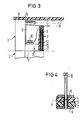
- FIG. 3 shows a partial section of the axial position of the cables integrated in the sealing body 1-2 interception device according to the invention.
- the interception device is inserted in this embodiment at the end of the inner part 13 of the sealing body 1-2, but this position is not the only possible one.
- the slit-shaped guide 7 is visible, in which the disks 6 for the generation of the interception pressure on the cables are inserted perpendicular to the dividing line 3 of the sealing body 1-2. It also becomes clear that the inserted disk 6 is only brought up to a distance D in the region of the dividing line 3, which corresponds approximately to the thickness of the sealing material inserted in the sealing area.
- the washer 6 projects with a protrusion 6a.
- the pressure bracket 8 now acts on this overhang 6a and is pressed down with the aid of the screw elements 10. In this way, the disc 6 is moved in the direction of the parting plane 3, where it generates the required interception pressure on all cables introduced.
- the sealing area 12 between the sealing body 1-2 and the surrounding sleeve pipe 16 as well as the connecting rail 19 for bridging the tensile or compressive forces between the two sealing bodies 1-2 are indicated.
- FIG. 4 finally illustrates the locking device required to generate the required pressure with the aid of the screw means 10.
- the upper pressure bracket 8 is provided with a screw 10, which is preferably arranged so that it cannot be lost, while the pressure bracket 9 below is provided with a threaded sleeve 11 that are in the holes of the sealing body halves 1 and 2 protrude.
- This threaded sleeve 11 is preferably also captively attached to the pressure bracket 9.
- it overhangs the dividing line 3 of the two sealing body halves 1 and 2. This ensures that when the dividing line 3 is filled with sealing compound, the bore or the thread remains free.
- a first centering can be carried out with the aid of these closure sleeves 11 during the assembly of the two seal body halves 1 and 2.
- the plates 6 for the cable interception direction can also be used if the cable entry openings are not cut out, that is to say if fixed cable entry openings are provided in the sealing area.
- panes can be used which also have prefabricated cable entry openings. It is then expedient to keep a certain set with corresponding diameter gradations available for different applications.
- the mode of operation does not change compared to the previously described exemplary embodiment, so that the object on which the invention is based is also achieved here.
- the sealing body halves 1 and 2 do not necessarily have to be closed or assembled at the same time as the plates for the interception device are pressed in, since the two processes are not dependent on one another. So it can also be advantageous to first assemble the sealing body halves and only then to actuate the cable clamp by pressing on the pressure bracket.
- thermoplastic material can be used as the material for the discs of the interception device, which has sufficient hardness for the transfer of the interception pressure.
- a correspondingly hard elastomer can also be used to limit the force, which yields itself when the permissible pressure is exceeded.
Landscapes
- Insulated Conductors (AREA)
- Installation Of Indoor Wiring (AREA)
- Cable Accessories (AREA)
- Processing Of Terminals (AREA)
- Insulating Bodies (AREA)
- Lining Or Joining Of Plastics Or The Like (AREA)
Abstract
Description
- Die Erfindung betrifft einen Dichtungskörper für Kabelgarnituren aus thermoplastischem Kunststoff, der in Einführungsrichtung Abdichtungselemente für einzuführende Kabel aufweist, wobei die Kabeleinführungsöffnungen den Durchmessern der Kabel anpaßbar sind.
- Aus der DE-PS 24 27 677 sind Dichtungskörper aus Kunststoff mit in Kabeleinführungsrichtung hintereinander liegenden, lamellenartigen Abdichtungselementen für längsgeteilte Kabelgarnituren und mit Einlagen aus plastischer Dichtungsmasse bekannt. Die lamellenartigen Abdichtungselemente werden durch Ausschneiden mit entsprechenden Hilfseinrichtungen den Durchmessern der einzuführenden Kabel angepaßt. Diese an den Stirnseiten der Kabelmuffe einzusetzenden Dichtungskörper werden mittels Verbindungsschienen zug- und drucksicher miteinander verbunden. Die Abfangung der Kabel erfolgt jedoch bei diesen Ausführungsformen unabhängig von den Dichtungskörpern, so daß zusätzliche davon unabhängige Abfangelemente eingesetzt werden müssen.
- Aufgabe vorliegender Erfindung ist nun, einen Dichtungskörper für derartige Kabelgarnituren zu schaffen, bei dem neben den Dichtungselementen auch die Abfangelemente für die eingeführten Kabel integriert sind. Die gestellte Aufgabe wird nun mit Hilfe eines Dichtungskörpers der eingangs geschilderten Art dadurch gelöst, daß der Dichtungskörper eine Führung und eine Klemmvorrichtung für eine auf den gesamten Umfang des eingeführten Kabels wirkende Abfangvorrichtung aufweist.
- Vorteile der Erfindung sind nun darin zu sehen, daß im Dichtungskörper neben dem Abdichtungsbereich auch die Abfangvorrichtung für die eingeführten Kabel angeordnet ist. Darüber hinaus ist vorteilhaft, daß nun mit dieser Abfangvorrichtung alle eingeführten Kabel gleichzeitig erfaßt werden, was bisher nicht möglich war; denn jedes Kabel mußte mit eigenen Mitteln abgefangen werden Neben der vereinfachten Bauweise sind also auch die Montagearbeiten gegenüber dem Stand der Technik erheblich verbessert, wobei die geforderten Richtlinien voll eingehalten werden können. Ferner ist erwähnenswert, daß durch entsprechende Dimensionierung die Druckelemente für die Kabelabfangung eine Verletzung der Kabelseele durch unzulässige Pressung praktisch ausgeschlossen werden kann.
- Die Erfindung wird nun anhand von vier Figuren näher erläutert.
- Figur 1 zeigt das Prinzip des erfindungsgemäßen DichtungsKörpers, in dem Dichtung und Abfangung vereint sind.
- Figur 2 zeigt ein Ausführungsbeispiel in einer Ansicht vom Inneren der Kabelmuffe heraus gegen den stirnseiigen Dichtungskörper.
- Figur 3 zeigt eine Seitenansicht dieses Dichtungskörpers ei offenem Muffenrohr.
- Figur 4 verdeutlicht die Verschraubung der Klemmvorrichtung für die Kabelabfangung.
- In der Figur 1 ist in einfacher Weise das Prinzip der im Dichtungskörper integrierten Kabelabfangung gemäß der Erfindung skizziert. Dort ist angedeutet, daß der aus zwei Teilen bestehende Dichtungskörper 1-2 in einem ersten Bereich durch die Einlage von entsprechendem Dichtungsmaterial 17 für die Abdichtung des eingeführten Kabels 18 herangezogen wird. In einem zweiten Bereich 14 erfolgt durch eingeschobene Scheiben 6 die Kabelabfangung, wobei in diesem Bereich eine noch zulässige Einschnürung des Kabels infolge der durch Klemmvorrichtungen eingepreßten Scheiben 6 erfolgt. Damit ist deutlich, daß die Abdichtung und Abfangung der Kabel im Dichtungskörper 1-2 zusammengefaßt sind. Die Einzelheiten hierüber werden in den folgenden Figuren näher erläutert.
- Die Figur 2 zeigt die Einzelheiten der im Dichtungskörper 1-2 integrierten Kabelabfangvorrichtung, die im Innenteil 13 des Dichtungskörpers 1-2 eingesetzt ist. Dieser Einsatz geht aus der später zu erläuternden Figur 3 besser hervor. In dieser Figur ist auch auf der Stirnfläche des Dichtungskörpers 1-2 der Bereich 4 kenntlich gemacht, in dem die Kabel der verschiedensten Durchmesser und Anzahl eingeführt werden. Dies ist auch der Bereich, in dem die integrierte Kabelabfangvorrichtung voll über alle Kabel hinweg wirksam sein muß. Im Dichtungsbereich des Dichtungskörpers 1-2 sind nun in Achsrichtung hintereinander liegende lamellenartige Abdichtungselemente angeordnet die entsprechend den Durchmessern und der Anzahl der einzuführenden Kabel ausgeschnitten bzw. aufgebohrt werden. Dies ist an sich bekannt. Für die neue Kabelabfangung hingegen ist nun ein ähnliches lamellenartiges Element als Scheibe 6 eingesetzt, doch ist diese Scheibe 6 seiner Aufgabe entsprechend mechanisch stärker ausgebildet, wird je doch ebenfalls beim Aufbohrvorgang für die Kabeleinführungen mit aufgebohrt, so daß sich auch hierfür keine zusätzlichen Arbeitsgänge ergeben. Weiterhin sind diese Scheiben 6 anders als die Abdichtungselemente senkrecht zur Achsrichtung des Dichtungskörpers 1-2 verschiebbar in einer Führung des Dichtungskörpers 1-2 angeordnet. Diese Führung ist im gezeigten Ausführungsbeispiel als Schlitz 7 ausgebildet, kann jedoch auch in anderer Weise erfolgen. Damit sind also die Voraussetzungen für das lagegerechte Umschließen der einzelnen eingeführten Kabel geschaffen; denn beim Zusammensetzen der Dichtungskörperhälften 1 und 2 ergeben sich die kreisförmigen Ausschnitte, in denen die Kabel geführt sind. Die Scheiben 6 sind allerdings beim Aufbohrvorgang nicht voll bis zur Teilungsebene 3 des Dichtungskörpers 1-2 eingeschoben, so daß die geschnittenen Öffnungen in den Scheiben 6 etwas kleiner sind als die Öffnungen in den fest angeordneten, lamellenartigen Abdichtungselementen. Dadurch wird erreicht, daß die Scheiben 6 beim Niederdrücken mit Hilfe der hierfür vorgesehenen Klemmvorrichtungen 8-9 den Kabelmantel aufgrund der verengten Öffnungen einpressen und ihn sogar bis zu einem zulässigen Maß einschnüren. Außerdem ist dabei noch zu berücksichtigen, daß in diesem Abfangbereich keine Abdichtungsmasse für die Abdichtung der Trennebene eingelegt ist, so daß die Scheiben mit ihren verengten Öffnungen direkt auf den Kabelmantel einwirken. Die Scheiben 6 besitzen nun vorzugsweise noch eine gerippte oder gitterförmige Oberflächenstruktur 15, wodurch bewirkt wird, daß sich die geschnittenen Kanten in den Öffnungen besser in den Kabelmantel eindrücken lassen. Durch die entstandene Querstruktur in der zum Kabelmantel gerichteten Auflageflächen der Scheiben 6 ergibt sich außerdem noch ein Schutz gegen Torsionskräfte. Die Scheiben 6 sind in ihrer Größe so dimensioniert, daß sie auf jeden Fall den vollen Einführungsbe reich 4 für die Kabel erfassen und weiterhin aus dem Dichtunskörperinnenteil 13 im Erfassungsbereich der hierfür vorgesehnen Klemmmvorrichtungen 8-9 mit Überständen 6a so weit überragen, daß genügender Abfangdruck auf die Kabel erzeugt werden kann. Andererseits kann durch geschickte Dimensionierung und entsprechenden Anschlägen auch dafür gesorgt werden, daß der Abfangdruck auf die Kabel den zulässigen Wert nicht übersteigt, so daß hierdurch die Kabelseele gegen Verletzung geschützt werden kann. Der Abfangdruck wird nun in diesem Ausführungsbeispiel mit Hilfe von U-förmigen Druckbügeln 8 und 9 erzielt, die über dem Innenteil 13 jedes Dichtungskörperteiles 1 bzw. 2 zum Beispiel unverlierbar angebracht sind. Diese Druckbügel 8 und 9 werden nach der Montage der Dichtungskörperteile 1 und 2 durch Schraubmittel 10, die über die Trennungslinie 3 hinwegreichen, zusammengepreßt, wobei durch Einwirkung der beiden Druckbügel 8 und 9 auf die Überstände 6a der Scheiben 6 in beiden Dichtungskörperhälften 1 und 2 der Abfangdruck auf die eingeführten Kabel erzeugt wird.
- Zur Übertragung der abgefangenen Kräfte sind wie bisher üblich an den stirnseitigen Dichtungskörpern 1-2 den Spleiß überbrückend Schienen 19 angeordnet. Im Dichtungskörper 1-2 ist weiterhin eine Durchführungsöffnung 5 zum Beispiel für Erdpotential vorgesehen, die bei der Gestaltung der Scheiben 6 für die Kabelabfangvorrichtung berücksichtigt werden müssen, wie aus der Figur hervorgeht. Weiterhin ist aus der Figur zu entnehmen, daß der montierte Dichtungskörper 1-2 von einem Muffenrohr 16 umgeben ist, das mit Hilfe eines hier nicht gezeigten Längsverschlusses aufgezogen wird.
- Die Figur 3 zeigt in einem Teilausschnitt die axiale Position der im Dichtungskörper 1-2 integrierten Kabel abfangvorrichtung gemäß der Erfindung. Die Abfangvorrichtung ist in diesem Ausführungsbeispiel am Ende des Innenteils 13 des Dichtungskörpers 1-2 eingeführt, jedoch ist diese Lage nicht die einzig mögliche. Im aufgebrochenen Teil des Dichtungskörperinnenteils 13 wird die schlitzförmige Führung 7 sichtbar, in der senkrecht zur Trennlinie 3 des Dichtungskörpers 1-2 die Scheiben 6 für die Erzeugung des Abfangdruckes auf die Kabel eingeführt ist. Dabei wird weiterhin deutlich, daß die eingeführte Scheibe 6 im Bereich der Trennlinie 3 nur bis auf einen Abstand D herangeführt ist, der in etwa der Dicke des im Dichtungsbereich eingelegten Dichtungsmaterials entspricht. Außerdem wird auf diese Weise bei der Herstellung der Einführungsöffnungen ein für die Pressung erforderlicher geringerer Durchmesser als bei den Dichtungselementen ausgeschnitten, wie vorher bereits näher erläutert wurde. Am oberen Ende des Dichtungskörperinnenteils 13 steht dagegen die Scheibe 6 mit einem Überstand 6a über. Auf diesen Überstand 6a wirkt nun der Druckbügel 8 ein, der mit Hilfe der Schraubelemente 10 niedergedrückt wird. Auf diese Weise wird die Scheibe 6 in Richtung der Trennungsebene 3 bewegt, wo sie auf alle eingeführten Kabeln den erforderlichen Abfangdruck erzeugt. Weiterhin ist skizzenhaft der Dichtungsbereich 12 zwischen dem Dichtungskörper 1-2 und dem umgebenden Muffenrohr 16 wie auch die Verbindungsschiene 19 zur Überbrückung der Zug- bzw. Druckkräfte zwischen den beiden Dichtungskörpern 1-2 angedeutet.
- Die Figur 4 verdeutlicht schließlich die zur Erzeugung des benötigten Druckes erforderliche Schließvorrichtung mit Hilfe der Schraubmittel 10. So ist jeweils der obere Druckbügel 8 mit einer Schraube 10 versehen, die vorzugsweise unverlierbar angeordnet ist, während der unten liegende Druckbügel 9 mit einer Gewindehülse 11 versehen ist, die in die Bohrungen der Dichtungskörper hälften 1 und 2 hineinragt. Diese Gewindehülse 11 ist vorzugsweise ebenfalls unverlierbar am Druckbügel 9 befestigt. Außerdem überragt sie die Trennungslinie 3 der beiden Dichtungskörperhälften 1 und 2. Auf diese Weise wird gewährleistet, daß beim Belegen der Trennungslinie 3 mit Dichtungsmasse die Bohrung bzw. das Gewinde freibleibt. Zusätzlich kann mit Hilfe dieser Verschlußhülsen 11 bei der Montage der beiden Dichtungskörperhälften 1 und 2 eine erste Zentrierung vorgenommen werden.
- Die Platten 6 für die Kabelabfangrichtung sind auch dann anwendbar, wenn die Kabeleinführungsöffnungen nicht ausgeschnitten werden, das heißt wenn feste Kabeleinführungsöffnungen im Dichtungsbereich vorgesehen sind. Bei solchen Anwendungsfällen können im Bereich der Kabelabfangung gemäß der Erfindung Scheiben eingesetzt werden, die bereits ebenfalls vorgefertigte Kabeleinführungsöffnungen aufweisen. Es ist dann zweckmäßig, für verschiedene Verwendungsfälle einen gewissen Satz mit entsprechenden Durchmesserabstufungen bereitzuhalten. In der Wirkungsweise ändert sich gegenüber dem vorher beschriebenen Ausführungsbeispiel nichts, so daß auch hier die der Erfindung zugrunde liegende Aufgabe erfüllt ist.
- Das Verschließen bzw. Zusammensetzen der Dichtungskörperhälften 1 und 2 muß nicht unbedingt gleichzeitig mit dem Einpressen der Platten für die Abfangvorrichtung erfolgen, denn die beiden Vorgänge sind nicht voneinander abhängig. So kann es auch vorteilhaft sein, zunächst die Dichtungskörperhälften zusammenzusetzen und anschließend erst durch Aufpressen der Druckbügel die Kabelabfangung zu betätigen.
- Als Werkstoff für die Scheiben der Abfangvorrichtung kommt jeder herkömmliche thermoplastische Kunststoff in Frage, der genügend Härte für die Übertragung des Abfangdruckes aufweist. Zur Kraftbegrenzung kann auch ein entsprechend harter Elastomer eingesetzt werden, der selbst nachgibt, wenn der zulässige Druck überschritten wird.
-
- 1 - erster Dichtungskörperhälfte
- 2 - zweite Dichtungskörperhälfte
- 3 - Teilungsebene
- 4 - Einführungsbereich
- 5 - Durchführungsöffnung
- 6 - Scheibe
- 6a - Überstand
- 7 - Schlitzförmige Führung
- 8 - Druckbügel
- 9 - Druckbügel
- 10 - Schraubelement
- 11 - Gewindehülse
- 12 - Dichtungsbereich
- 13 - Dichtungskörperinnenteil
- 14 - Dichtungsbereich
- 15 - gitterförmige Struktur
- 16 - Muffenrohr
- 17 - Dichtungsmaterial
- 18 - Kabel
- 19 - Verbindungsschiene
Claims (11)
Priority Applications (1)
| Application Number | Priority Date | Filing Date | Title |
|---|---|---|---|
| AT86114045T ATE100643T1 (de) | 1985-10-14 | 1986-10-10 | Dichtungskoerper fuer kabelgarnituren aus thermoplastischem kunststoff. |
Applications Claiming Priority (2)
| Application Number | Priority Date | Filing Date | Title |
|---|---|---|---|
| DE3536597 | 1985-10-14 | ||
| DE3536597 | 1985-10-14 |
Publications (3)
| Publication Number | Publication Date |
|---|---|
| EP0219072A2 true EP0219072A2 (de) | 1987-04-22 |
| EP0219072A3 EP0219072A3 (en) | 1989-08-30 |
| EP0219072B1 EP0219072B1 (de) | 1994-01-19 |
Family
ID=6283533
Family Applications (1)
| Application Number | Title | Priority Date | Filing Date |
|---|---|---|---|
| EP86114045A Expired - Lifetime EP0219072B1 (de) | 1985-10-14 | 1986-10-10 | Dichtungskörper für Kabelgarnituren aus thermoplastischem Kunststoff |
Country Status (6)
| Country | Link |
|---|---|
| US (1) | US4752653A (de) |
| EP (1) | EP0219072B1 (de) |
| AT (1) | ATE100643T1 (de) |
| AU (1) | AU589689B2 (de) |
| CA (1) | CA1335208C (de) |
| DE (1) | DE3689560D1 (de) |
Cited By (6)
| Publication number | Priority date | Publication date | Assignee | Title |
|---|---|---|---|---|
| GB2209410A (en) * | 1987-09-03 | 1989-05-10 | Sumitomo Electric Industries | Cable connecting box |
| US5006669A (en) * | 1989-07-18 | 1991-04-09 | Siemens Aktiengesellschaft | End member for a longitudinally divided cable sleeve |
| EP0752747A3 (de) * | 1995-07-03 | 1997-02-05 | Rxs Schrumpftech Garnituren | |
| EP0778643A1 (de) * | 1995-12-05 | 1997-06-11 | RXS Kabelgarnituren Gesellschaft mit beschränkter Haftung | Kabelmuffe mit Dichtungsteilen aus hintereinander liegenden Lamellen |
| WO2001013485A1 (de) * | 1999-08-13 | 2001-02-22 | Rxs Gesellschaft Für Vermögensverwaltung Mbh | Universale kabelgarnitur |
| WO2001041276A3 (de) * | 1999-12-02 | 2001-10-25 | Rxs Kabelgarnituren Gmbh & Co | Dichtungskörper für längsgeteilte kabelgarnituren |
Families Citing this family (4)
| Publication number | Priority date | Publication date | Assignee | Title |
|---|---|---|---|---|
| US5302779A (en) * | 1990-01-24 | 1994-04-12 | Etablissements Morel - Ateliers Electromechaniques De Favieres | Plug for fixing in an impermeable manner an electric cable to an opening and cable protection sleeve comprising such plugs |
| TW236043B (en) * | 1993-01-07 | 1994-12-11 | Rose Walter Gmbh & Co Kg | Closure for cables |
| US5387763A (en) * | 1993-05-13 | 1995-02-07 | Communications Technology Corporation | Enclosure for straight cable splice |
| US5679927A (en) * | 1993-05-13 | 1997-10-21 | Communications Technology Corporation | Buried service wire closure |
Family Cites Families (10)
| Publication number | Priority date | Publication date | Assignee | Title |
|---|---|---|---|---|
| DE7425454U (de) * | 1974-07-25 | 1974-11-07 | Siemens Ag | Lippenförmiger Dichtungskörper für Kabelmuffen |
| US4103911A (en) * | 1975-06-06 | 1978-08-01 | Siemens Aktiengesellschaft | Sealing member for cable inlets |
| DE2615314C3 (de) * | 1976-04-06 | 1980-09-25 | Krone Gmbh, 1000 Berlin | Kabelmuffe fur Nachrichtenkabel |
| DE2632852C3 (de) * | 1976-07-21 | 1981-07-16 | Siemens AG, 1000 Berlin und 8000 München | Adapter für Kabelanlagen |
| DE2652803C3 (de) * | 1976-11-19 | 1980-12-04 | Siemens Ag, 1000 Berlin Und 8000 Muenchen | Kabelgarnitur mit Lamellendichtung |
| DE7739190U1 (de) * | 1977-12-22 | 1978-04-06 | Siemens Ag, 1000 Berlin Und 8000 Muenchen | Dichtungskörper zum Einführen von Kabeln in Kabelgarnituren |
| DE2826584C2 (de) * | 1978-06-16 | 1982-04-08 | Siemens AG, 1000 Berlin und 8000 München | Dichtungskörper zur Einführung von Doppelmantelkabeln in Kabelgarnituren |
| BE885312A (fr) * | 1979-11-15 | 1981-01-16 | Morel Atel Electromec | Manchon pour proteger l'epissure de cables electriques ou telephoniques |
| DD159211A1 (de) * | 1981-05-29 | 1983-02-23 | Franz Kebschull | Anordnung zur lagebestimmung eines index gegenueber einer teilung |
| US4492816A (en) * | 1982-06-30 | 1985-01-08 | Etablissements Morel, Ateliers Electromecaniques De Favieres | Splice-protecting sleeve for electric cables or telephone cables |
-
1986
- 1986-10-10 AT AT86114045T patent/ATE100643T1/de not_active IP Right Cessation
- 1986-10-10 EP EP86114045A patent/EP0219072B1/de not_active Expired - Lifetime
- 1986-10-10 DE DE86114045T patent/DE3689560D1/de not_active Expired - Lifetime
- 1986-10-10 CA CA000520267A patent/CA1335208C/en not_active Expired - Fee Related
- 1986-10-13 AU AU63837/86A patent/AU589689B2/en not_active Ceased
- 1986-10-14 US US06/918,473 patent/US4752653A/en not_active Expired - Lifetime
Cited By (10)
| Publication number | Priority date | Publication date | Assignee | Title |
|---|---|---|---|---|
| GB2209410A (en) * | 1987-09-03 | 1989-05-10 | Sumitomo Electric Industries | Cable connecting box |
| US4914261A (en) * | 1987-09-03 | 1990-04-03 | Sumitomo Electric Industries, Ltd. | Cable connecting box |
| GB2209410B (en) * | 1987-09-03 | 1992-02-19 | Sumitomo Electric Industries | Cable connecting box |
| US5006669A (en) * | 1989-07-18 | 1991-04-09 | Siemens Aktiengesellschaft | End member for a longitudinally divided cable sleeve |
| EP0408967A3 (en) * | 1989-07-18 | 1991-10-16 | Siemens Aktiengesellschaft | Sealing body for longitudinally split cable fittings |
| EP0752747A3 (de) * | 1995-07-03 | 1997-02-05 | Rxs Schrumpftech Garnituren | |
| EP0778643A1 (de) * | 1995-12-05 | 1997-06-11 | RXS Kabelgarnituren Gesellschaft mit beschränkter Haftung | Kabelmuffe mit Dichtungsteilen aus hintereinander liegenden Lamellen |
| WO2001013485A1 (de) * | 1999-08-13 | 2001-02-22 | Rxs Gesellschaft Für Vermögensverwaltung Mbh | Universale kabelgarnitur |
| WO2001041276A3 (de) * | 1999-12-02 | 2001-10-25 | Rxs Kabelgarnituren Gmbh & Co | Dichtungskörper für längsgeteilte kabelgarnituren |
| US6802512B2 (en) | 1999-12-02 | 2004-10-12 | Ccs Technology, Inc. | Sealing body for longitudinally split cable fittings |
Also Published As
| Publication number | Publication date |
|---|---|
| EP0219072A3 (en) | 1989-08-30 |
| EP0219072B1 (de) | 1994-01-19 |
| US4752653A (en) | 1988-06-21 |
| AU589689B2 (en) | 1989-10-19 |
| DE3689560D1 (de) | 1994-03-03 |
| AU6383786A (en) | 1987-04-16 |
| ATE100643T1 (de) | 1994-02-15 |
| CA1335208C (en) | 1995-04-11 |
Similar Documents
| Publication | Publication Date | Title |
|---|---|---|
| DE2515939C3 (de) | Thermoplastklernmuffe mit Dichtungskörper | |
| DE2506948C2 (de) | Flanschverbindung | |
| DE9316172U1 (de) | Muffe zur Aufnahme von Abzweig- oder Verbindungsstellen von optischen oder elektrischen Kabeln | |
| EP1097496B1 (de) | Dichtungskörper für kabelgarnituren | |
| EP0219072B1 (de) | Dichtungskörper für Kabelgarnituren aus thermoplastischem Kunststoff | |
| DE102015112287A1 (de) | Explosionsgeschützte Anordnung und Verfahren zu deren Herstellung | |
| DE3025766C2 (de) | Kabeleinführung für Kabelgarnituren | |
| DE2736039C3 (de) | Aufteilungsmuffe nach dem Thermoplastklemmuffenprinzip | |
| DE3129570C2 (de) | Aufteilungsmuffe | |
| EP0543350A1 (de) | Kabelmuffe aus einem längsgeteilten Gehäuse | |
| DE2947139C2 (de) | Muffenkopf für längsgeteilte Kabelgarnituren | |
| AT410035B (de) | Abfangvorrichtung für ein optisches kabel | |
| DE2826584C2 (de) | Dichtungskörper zur Einführung von Doppelmantelkabeln in Kabelgarnituren | |
| EP3544132B1 (de) | Axial fixierbare dichtungsanordnung für eine kabeldurchführung | |
| DE29504754U1 (de) | Gehäuse mit einer Vorrichtung zur Kabelzugentlastung | |
| DE3937888C2 (de) | ||
| DE9205564U1 (de) | Durchführung für Rohre o.ä. | |
| DE19715885C2 (de) | Dichteinrichtung zum dichten Durchführen mindestens einer in einem Schutzrohr angeordneten Medienleitung durch eine Wandöffnung | |
| EP0638975A1 (de) | Muffenkopf mit mehreren geteilten Kabeleinführungen | |
| DE2652803A1 (de) | Kabelgarnitur mit lamellendichtung | |
| DE69006734T2 (de) | Schutzmuffe für elektrische Kabel und dazugehöriges Verfahren. | |
| DE4426241A1 (de) | Elektromaschine mit einem Rotor | |
| DE8120430U1 (de) | "Vorrichtung zum Abdichten von Kabeln" | |
| DE3127567A1 (de) | "vorrichtung zum abdichten von kabeln" | |
| DE3814215A1 (de) | Vorrichtung zum abdichten von schutzrohren fuer elektrische kabel |
Legal Events
| Date | Code | Title | Description |
|---|---|---|---|
| PUAI | Public reference made under article 153(3) epc to a published international application that has entered the european phase |
Free format text: ORIGINAL CODE: 0009012 |
|
| AK | Designated contracting states |
Kind code of ref document: A2 Designated state(s): AT BE CH DE FR GB IT LI NL SE |
|
| PUAL | Search report despatched |
Free format text: ORIGINAL CODE: 0009013 |
|
| AK | Designated contracting states |
Kind code of ref document: A3 Designated state(s): AT BE CH DE FR GB IT LI NL SE |
|
| 17P | Request for examination filed |
Effective date: 19890925 |
|
| 17Q | First examination report despatched |
Effective date: 19920225 |
|
| GRAA | (expected) grant |
Free format text: ORIGINAL CODE: 0009210 |
|
| AK | Designated contracting states |
Kind code of ref document: B1 Designated state(s): AT BE CH DE FR GB IT LI NL SE |
|
| REF | Corresponds to: |
Ref document number: 100643 Country of ref document: AT Date of ref document: 19940215 Kind code of ref document: T |
|
| REF | Corresponds to: |
Ref document number: 3689560 Country of ref document: DE Date of ref document: 19940303 |
|
| ET | Fr: translation filed | ||
| ITF | It: translation for a ep patent filed | ||
| GBT | Gb: translation of ep patent filed (gb section 77(6)(a)/1977) |
Effective date: 19940324 |
|
| PLBE | No opposition filed within time limit |
Free format text: ORIGINAL CODE: 0009261 |
|
| STAA | Information on the status of an ep patent application or granted ep patent |
Free format text: STATUS: NO OPPOSITION FILED WITHIN TIME LIMIT |
|
| 26N | No opposition filed | ||
| EAL | Se: european patent in force in sweden |
Ref document number: 86114045.7 |
|
| PGFP | Annual fee paid to national office [announced via postgrant information from national office to epo] |
Ref country code: FR Payment date: 20000919 Year of fee payment: 15 |
|
| PGFP | Annual fee paid to national office [announced via postgrant information from national office to epo] |
Ref country code: AT Payment date: 20000921 Year of fee payment: 15 |
|
| PGFP | Annual fee paid to national office [announced via postgrant information from national office to epo] |
Ref country code: SE Payment date: 20010920 Year of fee payment: 16 |
|
| PGFP | Annual fee paid to national office [announced via postgrant information from national office to epo] |
Ref country code: GB Payment date: 20010921 Year of fee payment: 16 |
|
| PGFP | Annual fee paid to national office [announced via postgrant information from national office to epo] |
Ref country code: CH Payment date: 20010924 Year of fee payment: 16 |
|
| PGFP | Annual fee paid to national office [announced via postgrant information from national office to epo] |
Ref country code: NL Payment date: 20010925 Year of fee payment: 16 |
|
| PG25 | Lapsed in a contracting state [announced via postgrant information from national office to epo] |
Ref country code: AT Free format text: LAPSE BECAUSE OF NON-PAYMENT OF DUE FEES Effective date: 20011010 |
|
| REG | Reference to a national code |
Ref country code: GB Ref legal event code: IF02 |
|
| PG25 | Lapsed in a contracting state [announced via postgrant information from national office to epo] |
Ref country code: FR Free format text: LAPSE BECAUSE OF NON-PAYMENT OF DUE FEES Effective date: 20020628 |
|
| REG | Reference to a national code |
Ref country code: FR Ref legal event code: ST |
|
| PG25 | Lapsed in a contracting state [announced via postgrant information from national office to epo] |
Ref country code: GB Free format text: LAPSE BECAUSE OF NON-PAYMENT OF DUE FEES Effective date: 20021010 |
|
| PG25 | Lapsed in a contracting state [announced via postgrant information from national office to epo] |
Ref country code: SE Free format text: LAPSE BECAUSE OF NON-PAYMENT OF DUE FEES Effective date: 20021011 |
|
| PG25 | Lapsed in a contracting state [announced via postgrant information from national office to epo] |
Ref country code: LI Free format text: LAPSE BECAUSE OF NON-PAYMENT OF DUE FEES Effective date: 20021031 Ref country code: CH Free format text: LAPSE BECAUSE OF NON-PAYMENT OF DUE FEES Effective date: 20021031 |
|
| PG25 | Lapsed in a contracting state [announced via postgrant information from national office to epo] |
Ref country code: NL Free format text: LAPSE BECAUSE OF NON-PAYMENT OF DUE FEES Effective date: 20030501 |
|
| GBPC | Gb: european patent ceased through non-payment of renewal fee |
Effective date: 20021010 |
|
| EUG | Se: european patent has lapsed | ||
| REG | Reference to a national code |
Ref country code: CH Ref legal event code: PL |
|
| NLV4 | Nl: lapsed or anulled due to non-payment of the annual fee |
Effective date: 20030501 |
|
| PG25 | Lapsed in a contracting state [announced via postgrant information from national office to epo] |
Ref country code: IT Free format text: LAPSE BECAUSE OF NON-PAYMENT OF DUE FEES Effective date: 20051010 |
|
| PGFP | Annual fee paid to national office [announced via postgrant information from national office to epo] |
Ref country code: BE Payment date: 20051122 Year of fee payment: 20 |
|
| PGFP | Annual fee paid to national office [announced via postgrant information from national office to epo] |
Ref country code: DE Payment date: 20051130 Year of fee payment: 20 |
|
| BE20 | Be: patent expired |
Owner name: *CCS TECHNOLOGY INC. Effective date: 20061010 |