EP0219072A2 - Corps d'étanchéité pour garnitures de câble en matière synthétique thermoplastique - Google Patents
Corps d'étanchéité pour garnitures de câble en matière synthétique thermoplastique Download PDFInfo
- Publication number
- EP0219072A2 EP0219072A2 EP86114045A EP86114045A EP0219072A2 EP 0219072 A2 EP0219072 A2 EP 0219072A2 EP 86114045 A EP86114045 A EP 86114045A EP 86114045 A EP86114045 A EP 86114045A EP 0219072 A2 EP0219072 A2 EP 0219072A2
- Authority
- EP
- European Patent Office
- Prior art keywords
- sealing body
- sealing
- cable
- body according
- disks
- Prior art date
- Legal status (The legal status is an assumption and is not a legal conclusion. Google has not performed a legal analysis and makes no representation as to the accuracy of the status listed.)
- Granted
Links
Images

Classifications
-
- H—ELECTRICITY
- H02—GENERATION; CONVERSION OR DISTRIBUTION OF ELECTRIC POWER
- H02G—INSTALLATION OF ELECTRIC CABLES OR LINES, OR OF COMBINED OPTICAL AND ELECTRIC CABLES OR LINES
- H02G15/00—Cable fittings
- H02G15/013—Sealing means for cable inlets
Definitions
- the invention relates to a sealing body for cable fittings made of thermoplastic material, which has sealing elements in the direction of insertion for cables to be inserted, the cable insertion openings being adaptable to the diameters of the cables.
- sealing body made of plastic with lamella-like sealing elements lying one behind the other in the cable insertion direction for longitudinally divided cable fittings and with inserts made of plastic sealing compound are known.
- the lamellar sealing elements are adapted to the diameters of the cables to be inserted by cutting out with appropriate auxiliary devices.
- These sealing bodies to be used on the end faces of the cable sleeve are connected to one another in a tension-proof and pressure-proof manner by means of connecting rails. In these embodiments, however, the cables are intercepted independently of the sealing bodies, so that additional intercepting elements that are independent of them must be used.
- the object of the present invention is now to create a sealing body for such cable sets, in which, in addition to the sealing elements, the interception elements for the inserted cables are also integrated.
- the task is now solved with the help of a sealing body of the type described in that the sealing body has a guide and a clamping device for a has interception device acting on the entire circumference of the inserted cable.
- the interception device for the inserted cables is also arranged in the sealing body.
- this intercepting device all the cables introduced are detected simultaneously, which was previously not possible; because each cable had to be intercepted with its own resources.
- the assembly work is also considerably improved over the prior art, and the required guidelines can be fully complied with.
- the pressure elements for the cable support can practically preclude injury to the cable core due to inadmissible pressure.
- the principle of integrated cable strain relief according to the invention is outlined in a simple manner. It is indicated there that the sealing body 1-2, consisting of two parts, is used in a first area through the insertion of appropriate sealing material 17 for the sealing of the inserted cable 18. In a second area 14, the cables are intercepted by inserted washers 6, in which area the cable is still constricted as a result of the washers 6 pressed in by clamping devices. This makes it clear that the sealing and interception of the cables are combined in the sealing body 1-2. The details of this are explained in more detail in the following figures.
- FIG. 2 shows the details of the cable interception device integrated in the sealing body 1-2, which is inserted in the inner part 13 of the sealing body 1-2. This use can be seen better in FIG. 3 to be explained later.
- the area 4 is also identified on the end face of the sealing body 1-2, in which the cables of various diameters and numbers are inserted. This is also the area in which the integrated cable interception device must be fully effective across all cables.
- lamella-like sealing elements are now arranged one behind the other in the axial direction and are cut out or drilled out according to the diameter and the number of cables to be inserted. This is known per se.
- this disc 6 is mechanically stronger according to its task, will but also also drilled out during the drilling process for the cable entries, so that there are no additional operations for this either.
- these disks 6 are arranged such that they can be displaced perpendicularly to the axial direction of the sealing body 1-2 in a guide of the sealing body 1-2.
- this guide is designed as a slot 7, but can also take place in another way. This creates the prerequisites for enclosing the individual cables introduced in the correct position; because when assembling the seal body halves 1 and 2, there are circular cutouts in which the cables are guided.
- the disks 6 are not fully pushed in as far as the parting plane 3 of the sealing body 1-2 during the boring process, so that the cut openings in the disks 6 are somewhat smaller than the openings in the fixed, lamellar sealing elements. It is thereby achieved that the washers 6 press in the cable sheath when pressed down with the aid of the clamping devices 8-9 provided for this purpose, and even constrict it to an admissible extent. In addition, it must also be taken into account that no sealing compound for sealing the parting plane is inserted in this interception area, so that the disks act directly on the cable sheath with their narrowed openings.
- the disks 6 now preferably have a ribbed or lattice-shaped surface structure 15, as a result of which the cut edges in the openings can be better pressed into the cable sheath.
- the resulting transverse structure in the support surfaces of the panes 6 directed towards the cable sheath also provides protection against torsional forces.
- the disks 6 are dimensioned in such a way that they are definitely the full introduction Capture rich 4 for the cables and continue to protrude from the sealing body inner part 13 in the detection area of the clamping devices 8-9 provided for this purpose with protrusions 6a so that sufficient interception pressure can be generated on the cables.
- rails 19 are arranged to bridge the splice on the front sealing bodies 1-2, as was customary hitherto.
- the sealing body 1-2 there is also a through opening 5, for example for earth potential, which must be taken into account when designing the disks 6 for the cable interception device, as can be seen from the figure.
- the assembled sealing body 1-2 is surrounded by a sleeve tube 16, which is pulled open with the aid of a longitudinal closure, not shown here.
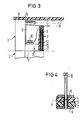
- FIG. 3 shows a partial section of the axial position of the cables integrated in the sealing body 1-2 interception device according to the invention.
- the interception device is inserted in this embodiment at the end of the inner part 13 of the sealing body 1-2, but this position is not the only possible one.
- the slit-shaped guide 7 is visible, in which the disks 6 for the generation of the interception pressure on the cables are inserted perpendicular to the dividing line 3 of the sealing body 1-2. It also becomes clear that the inserted disk 6 is only brought up to a distance D in the region of the dividing line 3, which corresponds approximately to the thickness of the sealing material inserted in the sealing area.
- the washer 6 projects with a protrusion 6a.
- the pressure bracket 8 now acts on this overhang 6a and is pressed down with the aid of the screw elements 10. In this way, the disc 6 is moved in the direction of the parting plane 3, where it generates the required interception pressure on all cables introduced.
- the sealing area 12 between the sealing body 1-2 and the surrounding sleeve pipe 16 as well as the connecting rail 19 for bridging the tensile or compressive forces between the two sealing bodies 1-2 are indicated.
- FIG. 4 finally illustrates the locking device required to generate the required pressure with the aid of the screw means 10.
- the upper pressure bracket 8 is provided with a screw 10, which is preferably arranged so that it cannot be lost, while the pressure bracket 9 below is provided with a threaded sleeve 11 that are in the holes of the sealing body halves 1 and 2 protrude.
- This threaded sleeve 11 is preferably also captively attached to the pressure bracket 9.
- it overhangs the dividing line 3 of the two sealing body halves 1 and 2. This ensures that when the dividing line 3 is filled with sealing compound, the bore or the thread remains free.
- a first centering can be carried out with the aid of these closure sleeves 11 during the assembly of the two seal body halves 1 and 2.
- the plates 6 for the cable interception direction can also be used if the cable entry openings are not cut out, that is to say if fixed cable entry openings are provided in the sealing area.
- panes can be used which also have prefabricated cable entry openings. It is then expedient to keep a certain set with corresponding diameter gradations available for different applications.
- the mode of operation does not change compared to the previously described exemplary embodiment, so that the object on which the invention is based is also achieved here.
- the sealing body halves 1 and 2 do not necessarily have to be closed or assembled at the same time as the plates for the interception device are pressed in, since the two processes are not dependent on one another. So it can also be advantageous to first assemble the sealing body halves and only then to actuate the cable clamp by pressing on the pressure bracket.
- thermoplastic material can be used as the material for the discs of the interception device, which has sufficient hardness for the transfer of the interception pressure.
- a correspondingly hard elastomer can also be used to limit the force, which yields itself when the permissible pressure is exceeded.
Landscapes
- Insulated Conductors (AREA)
- Installation Of Indoor Wiring (AREA)
- Cable Accessories (AREA)
- Processing Of Terminals (AREA)
- Insulating Bodies (AREA)
- Lining Or Joining Of Plastics Or The Like (AREA)
Priority Applications (1)
| Application Number | Priority Date | Filing Date | Title |
|---|---|---|---|
| AT86114045T ATE100643T1 (de) | 1985-10-14 | 1986-10-10 | Dichtungskoerper fuer kabelgarnituren aus thermoplastischem kunststoff. |
Applications Claiming Priority (2)
| Application Number | Priority Date | Filing Date | Title |
|---|---|---|---|
| DE3536597 | 1985-10-14 | ||
| DE3536597 | 1985-10-14 |
Publications (3)
| Publication Number | Publication Date |
|---|---|
| EP0219072A2 true EP0219072A2 (fr) | 1987-04-22 |
| EP0219072A3 EP0219072A3 (en) | 1989-08-30 |
| EP0219072B1 EP0219072B1 (fr) | 1994-01-19 |
Family
ID=6283533
Family Applications (1)
| Application Number | Title | Priority Date | Filing Date |
|---|---|---|---|
| EP86114045A Expired - Lifetime EP0219072B1 (fr) | 1985-10-14 | 1986-10-10 | Corps d'étanchéité pour garnitures de câble en matière synthétique thermoplastique |
Country Status (6)
| Country | Link |
|---|---|
| US (1) | US4752653A (fr) |
| EP (1) | EP0219072B1 (fr) |
| AT (1) | ATE100643T1 (fr) |
| AU (1) | AU589689B2 (fr) |
| CA (1) | CA1335208C (fr) |
| DE (1) | DE3689560D1 (fr) |
Cited By (6)
| Publication number | Priority date | Publication date | Assignee | Title |
|---|---|---|---|---|
| GB2209410A (en) * | 1987-09-03 | 1989-05-10 | Sumitomo Electric Industries | Cable connecting box |
| EP0408967A2 (fr) * | 1989-07-18 | 1991-01-23 | Siemens Aktiengesellschaft | Corps d'étanchéité pour garnitures de câbles divisées longitudinalement |
| EP0752747A2 (fr) * | 1995-07-03 | 1997-01-08 | RXS Kabelgarnituren Gesellschaft mit beschränkter Haftung | Dispositif de rétention de câble à l'introduction de câble |
| EP0778643A1 (fr) * | 1995-12-05 | 1997-06-11 | RXS Kabelgarnituren Gesellschaft mit beschränkter Haftung | Manchon de câble à parties d'étanchéité comprenant des lamelles disposée l'une derrière l'autre |
| WO2001013485A1 (fr) * | 1999-08-13 | 2001-02-22 | Rxs Gesellschaft Für Vermögensverwaltung Mbh | Manchon universel pour cables |
| WO2001041276A2 (fr) * | 1999-12-02 | 2001-06-07 | Ccs Technology, Inc. | Corps d'etancheite pour garnitures de cable reparties en longueur |
Families Citing this family (4)
| Publication number | Priority date | Publication date | Assignee | Title |
|---|---|---|---|---|
| AU654273B2 (en) * | 1990-01-24 | 1994-11-03 | Etablissements Morel-Ateliers Electromecnaiques De Favieres | Plug for sealingly securing an electric cable in an opening and cable protection sleeve comprising a number of said plugs |
| TW236043B (en) * | 1993-01-07 | 1994-12-11 | Rose Walter Gmbh & Co Kg | Closure for cables |
| US5679927A (en) * | 1993-05-13 | 1997-10-21 | Communications Technology Corporation | Buried service wire closure |
| US5387763A (en) * | 1993-05-13 | 1995-02-07 | Communications Technology Corporation | Enclosure for straight cable splice |
Citations (4)
| Publication number | Priority date | Publication date | Assignee | Title |
|---|---|---|---|---|
| DE2632852A1 (de) * | 1976-07-21 | 1978-01-26 | Siemens Ag | Adapter fuer kabelanlagen |
| DE2615314A1 (de) * | 1976-04-06 | 1978-02-23 | Krone Gmbh | Kabelgarnitur, insbesondere kabelmuffe fuer nachrichtenkabel |
| EP0002789A1 (fr) * | 1977-12-22 | 1979-07-11 | Siemens Aktiengesellschaft | Corps d'étanchéité pour l'introduction de câbles dans des garnitures de câbles |
| WO1981001487A1 (fr) * | 1979-11-15 | 1981-05-28 | Morel Atel Elect | Manchon pour proteger l'epissure de cables electriques ou telephoniques |
Family Cites Families (6)
| Publication number | Priority date | Publication date | Assignee | Title |
|---|---|---|---|---|
| DE7425454U (de) * | 1974-07-25 | 1974-11-07 | Siemens Ag | Lippenförmiger Dichtungskörper für Kabelmuffen |
| US4103911A (en) * | 1975-06-06 | 1978-08-01 | Siemens Aktiengesellschaft | Sealing member for cable inlets |
| DE2652803C3 (de) * | 1976-11-19 | 1980-12-04 | Siemens Ag, 1000 Berlin Und 8000 Muenchen | Kabelgarnitur mit Lamellendichtung |
| DE2826584C2 (de) * | 1978-06-16 | 1982-04-08 | Siemens AG, 1000 Berlin und 8000 München | Dichtungskörper zur Einführung von Doppelmantelkabeln in Kabelgarnituren |
| DD159211A1 (de) * | 1981-05-29 | 1983-02-23 | Franz Kebschull | Anordnung zur lagebestimmung eines index gegenueber einer teilung |
| US4492816A (en) * | 1982-06-30 | 1985-01-08 | Etablissements Morel, Ateliers Electromecaniques De Favieres | Splice-protecting sleeve for electric cables or telephone cables |
-
1986
- 1986-10-10 CA CA000520267A patent/CA1335208C/fr not_active Expired - Fee Related
- 1986-10-10 EP EP86114045A patent/EP0219072B1/fr not_active Expired - Lifetime
- 1986-10-10 AT AT86114045T patent/ATE100643T1/de not_active IP Right Cessation
- 1986-10-10 DE DE86114045T patent/DE3689560D1/de not_active Expired - Lifetime
- 1986-10-13 AU AU63837/86A patent/AU589689B2/en not_active Ceased
- 1986-10-14 US US06/918,473 patent/US4752653A/en not_active Expired - Lifetime
Patent Citations (4)
| Publication number | Priority date | Publication date | Assignee | Title |
|---|---|---|---|---|
| DE2615314A1 (de) * | 1976-04-06 | 1978-02-23 | Krone Gmbh | Kabelgarnitur, insbesondere kabelmuffe fuer nachrichtenkabel |
| DE2632852A1 (de) * | 1976-07-21 | 1978-01-26 | Siemens Ag | Adapter fuer kabelanlagen |
| EP0002789A1 (fr) * | 1977-12-22 | 1979-07-11 | Siemens Aktiengesellschaft | Corps d'étanchéité pour l'introduction de câbles dans des garnitures de câbles |
| WO1981001487A1 (fr) * | 1979-11-15 | 1981-05-28 | Morel Atel Elect | Manchon pour proteger l'epissure de cables electriques ou telephoniques |
Cited By (13)
| Publication number | Priority date | Publication date | Assignee | Title |
|---|---|---|---|---|
| GB2209410A (en) * | 1987-09-03 | 1989-05-10 | Sumitomo Electric Industries | Cable connecting box |
| US4914261A (en) * | 1987-09-03 | 1990-04-03 | Sumitomo Electric Industries, Ltd. | Cable connecting box |
| GB2209410B (en) * | 1987-09-03 | 1992-02-19 | Sumitomo Electric Industries | Cable connecting box |
| EP0408967A2 (fr) * | 1989-07-18 | 1991-01-23 | Siemens Aktiengesellschaft | Corps d'étanchéité pour garnitures de câbles divisées longitudinalement |
| US5006669A (en) * | 1989-07-18 | 1991-04-09 | Siemens Aktiengesellschaft | End member for a longitudinally divided cable sleeve |
| EP0408967A3 (en) * | 1989-07-18 | 1991-10-16 | Siemens Aktiengesellschaft | Sealing body for longitudinally split cable fittings |
| EP0752747A2 (fr) * | 1995-07-03 | 1997-01-08 | RXS Kabelgarnituren Gesellschaft mit beschränkter Haftung | Dispositif de rétention de câble à l'introduction de câble |
| EP0752747A3 (fr) * | 1995-07-03 | 1997-02-05 | Rxs Schrumpftech Garnituren | |
| EP0778643A1 (fr) * | 1995-12-05 | 1997-06-11 | RXS Kabelgarnituren Gesellschaft mit beschränkter Haftung | Manchon de câble à parties d'étanchéité comprenant des lamelles disposée l'une derrière l'autre |
| WO2001013485A1 (fr) * | 1999-08-13 | 2001-02-22 | Rxs Gesellschaft Für Vermögensverwaltung Mbh | Manchon universel pour cables |
| WO2001041276A2 (fr) * | 1999-12-02 | 2001-06-07 | Ccs Technology, Inc. | Corps d'etancheite pour garnitures de cable reparties en longueur |
| WO2001041276A3 (fr) * | 1999-12-02 | 2001-10-25 | Rxs Kabelgarnituren Gmbh & Co | Corps d'etancheite pour garnitures de cable reparties en longueur |
| US6802512B2 (en) | 1999-12-02 | 2004-10-12 | Ccs Technology, Inc. | Sealing body for longitudinally split cable fittings |
Also Published As
| Publication number | Publication date |
|---|---|
| EP0219072A3 (en) | 1989-08-30 |
| ATE100643T1 (de) | 1994-02-15 |
| EP0219072B1 (fr) | 1994-01-19 |
| AU589689B2 (en) | 1989-10-19 |
| DE3689560D1 (de) | 1994-03-03 |
| US4752653A (en) | 1988-06-21 |
| AU6383786A (en) | 1987-04-16 |
| CA1335208C (fr) | 1995-04-11 |
Similar Documents
| Publication | Publication Date | Title |
|---|---|---|
| DE2515939C3 (de) | Thermoplastklernmuffe mit Dichtungskörper | |
| DE2506948C2 (de) | Flanschverbindung | |
| EP3329566B1 (fr) | Dispositif antidéflagrant et procédé de fabrication de celui-ci | |
| EP0408967A2 (fr) | Corps d'étanchéité pour garnitures de câbles divisées longitudinalement | |
| EP1097496B1 (fr) | Corps d'etancheite pour garnitures de cables | |
| EP0219072B1 (fr) | Corps d'étanchéité pour garnitures de câble en matière synthétique thermoplastique | |
| DE3025766C2 (de) | Kabeleinführung für Kabelgarnituren | |
| DE2736039C3 (de) | Aufteilungsmuffe nach dem Thermoplastklemmuffenprinzip | |
| EP0543350A1 (fr) | Manchon de câble comprenant un boîtier divisé longitudinalement | |
| DE3129570C2 (de) | Aufteilungsmuffe | |
| DE2947139C2 (de) | Muffenkopf für längsgeteilte Kabelgarnituren | |
| DE3739714C1 (en) | Device for closing and sealing the free end of a cable conduit | |
| EP3544132B1 (fr) | Dispositif d'étanchéité axial pouvant être fixé pour un passage des câbles | |
| DE2938006C2 (de) | Vorrichtung zum Verbinden zweier glatter Rohrenden | |
| AT410035B (de) | Abfangvorrichtung für ein optisches kabel | |
| DE2826584C2 (de) | Dichtungskörper zur Einführung von Doppelmantelkabeln in Kabelgarnituren | |
| CH689683A5 (de) | Gehaeuse mit einer Vorrichtung zur Kabelzugentlastung. | |
| DE3937888C2 (fr) | ||
| EP0566973A1 (fr) | Traversée pour tuyaux ou similaires | |
| EP0638975A1 (fr) | Extrémité de manchon à pluralité d'entrées subdivisées de câbles | |
| DE2652803A1 (de) | Kabelgarnitur mit lamellendichtung | |
| DE19715885C2 (de) | Dichteinrichtung zum dichten Durchführen mindestens einer in einem Schutzrohr angeordneten Medienleitung durch eine Wandöffnung | |
| EP0789823B1 (fr) | Systeme demontable d'assemblage et d'etancheite pour transmettre des forces de traction axiales ou des forces de pression hydraulique | |
| DE4426241A1 (de) | Elektromaschine mit einem Rotor | |
| DE8120430U1 (de) | "Vorrichtung zum Abdichten von Kabeln" |
Legal Events
| Date | Code | Title | Description |
|---|---|---|---|
| PUAI | Public reference made under article 153(3) epc to a published international application that has entered the european phase |
Free format text: ORIGINAL CODE: 0009012 |
|
| AK | Designated contracting states |
Kind code of ref document: A2 Designated state(s): AT BE CH DE FR GB IT LI NL SE |
|
| PUAL | Search report despatched |
Free format text: ORIGINAL CODE: 0009013 |
|
| AK | Designated contracting states |
Kind code of ref document: A3 Designated state(s): AT BE CH DE FR GB IT LI NL SE |
|
| 17P | Request for examination filed |
Effective date: 19890925 |
|
| 17Q | First examination report despatched |
Effective date: 19920225 |
|
| GRAA | (expected) grant |
Free format text: ORIGINAL CODE: 0009210 |
|
| AK | Designated contracting states |
Kind code of ref document: B1 Designated state(s): AT BE CH DE FR GB IT LI NL SE |
|
| REF | Corresponds to: |
Ref document number: 100643 Country of ref document: AT Date of ref document: 19940215 Kind code of ref document: T |
|
| REF | Corresponds to: |
Ref document number: 3689560 Country of ref document: DE Date of ref document: 19940303 |
|
| ET | Fr: translation filed | ||
| ITF | It: translation for a ep patent filed |
Owner name: STUDIO JAUMANN |
|
| GBT | Gb: translation of ep patent filed (gb section 77(6)(a)/1977) |
Effective date: 19940324 |
|
| PLBE | No opposition filed within time limit |
Free format text: ORIGINAL CODE: 0009261 |
|
| STAA | Information on the status of an ep patent application or granted ep patent |
Free format text: STATUS: NO OPPOSITION FILED WITHIN TIME LIMIT |
|
| 26N | No opposition filed | ||
| EAL | Se: european patent in force in sweden |
Ref document number: 86114045.7 |
|
| PGFP | Annual fee paid to national office [announced via postgrant information from national office to epo] |
Ref country code: FR Payment date: 20000919 Year of fee payment: 15 |
|
| PGFP | Annual fee paid to national office [announced via postgrant information from national office to epo] |
Ref country code: AT Payment date: 20000921 Year of fee payment: 15 |
|
| PGFP | Annual fee paid to national office [announced via postgrant information from national office to epo] |
Ref country code: SE Payment date: 20010920 Year of fee payment: 16 |
|
| PGFP | Annual fee paid to national office [announced via postgrant information from national office to epo] |
Ref country code: GB Payment date: 20010921 Year of fee payment: 16 |
|
| PGFP | Annual fee paid to national office [announced via postgrant information from national office to epo] |
Ref country code: CH Payment date: 20010924 Year of fee payment: 16 |
|
| PGFP | Annual fee paid to national office [announced via postgrant information from national office to epo] |
Ref country code: NL Payment date: 20010925 Year of fee payment: 16 |
|
| PG25 | Lapsed in a contracting state [announced via postgrant information from national office to epo] |
Ref country code: AT Free format text: LAPSE BECAUSE OF NON-PAYMENT OF DUE FEES Effective date: 20011010 |
|
| REG | Reference to a national code |
Ref country code: GB Ref legal event code: IF02 |
|
| PG25 | Lapsed in a contracting state [announced via postgrant information from national office to epo] |
Ref country code: FR Free format text: LAPSE BECAUSE OF NON-PAYMENT OF DUE FEES Effective date: 20020628 |
|
| REG | Reference to a national code |
Ref country code: FR Ref legal event code: ST |
|
| PG25 | Lapsed in a contracting state [announced via postgrant information from national office to epo] |
Ref country code: GB Free format text: LAPSE BECAUSE OF NON-PAYMENT OF DUE FEES Effective date: 20021010 |
|
| PG25 | Lapsed in a contracting state [announced via postgrant information from national office to epo] |
Ref country code: SE Free format text: LAPSE BECAUSE OF NON-PAYMENT OF DUE FEES Effective date: 20021011 |
|
| PG25 | Lapsed in a contracting state [announced via postgrant information from national office to epo] |
Ref country code: LI Free format text: LAPSE BECAUSE OF NON-PAYMENT OF DUE FEES Effective date: 20021031 Ref country code: CH Free format text: LAPSE BECAUSE OF NON-PAYMENT OF DUE FEES Effective date: 20021031 |
|
| PG25 | Lapsed in a contracting state [announced via postgrant information from national office to epo] |
Ref country code: NL Free format text: LAPSE BECAUSE OF NON-PAYMENT OF DUE FEES Effective date: 20030501 |
|
| GBPC | Gb: european patent ceased through non-payment of renewal fee |
Effective date: 20021010 |
|
| EUG | Se: european patent has lapsed | ||
| REG | Reference to a national code |
Ref country code: CH Ref legal event code: PL |
|
| NLV4 | Nl: lapsed or anulled due to non-payment of the annual fee |
Effective date: 20030501 |
|
| PG25 | Lapsed in a contracting state [announced via postgrant information from national office to epo] |
Ref country code: IT Free format text: LAPSE BECAUSE OF NON-PAYMENT OF DUE FEES Effective date: 20051010 |
|
| PGFP | Annual fee paid to national office [announced via postgrant information from national office to epo] |
Ref country code: BE Payment date: 20051122 Year of fee payment: 20 |
|
| PGFP | Annual fee paid to national office [announced via postgrant information from national office to epo] |
Ref country code: DE Payment date: 20051130 Year of fee payment: 20 |
|
| BE20 | Be: patent expired |
Owner name: *CCS TECHNOLOGY INC. Effective date: 20061010 |