EP0217408B1 - Verfahren und Vorrichtung zur Höhenregulierung einer Nivellierungsbohle - Google Patents
Verfahren und Vorrichtung zur Höhenregulierung einer Nivellierungsbohle Download PDFInfo
- Publication number
- EP0217408B1 EP0217408B1 EP86113678A EP86113678A EP0217408B1 EP 0217408 B1 EP0217408 B1 EP 0217408B1 EP 86113678 A EP86113678 A EP 86113678A EP 86113678 A EP86113678 A EP 86113678A EP 0217408 B1 EP0217408 B1 EP 0217408B1
- Authority
- EP
- European Patent Office
- Prior art keywords
- lifting
- levelling
- switched
- height
- screed
- Prior art date
- Legal status (The legal status is an assumption and is not a legal conclusion. Google has not performed a legal analysis and makes no representation as to the accuracy of the status listed.)
- Expired - Lifetime
Links
Images

Classifications
-
- E—FIXED CONSTRUCTIONS
- E01—CONSTRUCTION OF ROADS, RAILWAYS, OR BRIDGES
- E01C—CONSTRUCTION OF, OR SURFACES FOR, ROADS, SPORTS GROUNDS, OR THE LIKE; MACHINES OR AUXILIARY TOOLS FOR CONSTRUCTION OR REPAIR
- E01C19/00—Machines, tools or auxiliary devices for preparing or distributing paving materials, for working the placed materials, or for forming, consolidating, or finishing the paving
- E01C19/48—Machines, tools or auxiliary devices for preparing or distributing paving materials, for working the placed materials, or for forming, consolidating, or finishing the paving for laying-down the materials and consolidating them, or finishing the surface, e.g. slip forms therefor, forming kerbs or gutters in a continuous operation in situ
- E01C19/4866—Machines, tools or auxiliary devices for preparing or distributing paving materials, for working the placed materials, or for forming, consolidating, or finishing the paving for laying-down the materials and consolidating them, or finishing the surface, e.g. slip forms therefor, forming kerbs or gutters in a continuous operation in situ with solely non-vibratory or non-percussive pressing or smoothing means for consolidating or finishing
- E01C19/4873—Apparatus designed for railless operation
Definitions
- the invention relates to a method according to the preamble of claim 1.
- the layer thickness is essentially determined by the angle of attack of the screed to the paving ground and its driving speed in connection with the flow and compaction behavior of the paving material. It is known (US-A-4 026 658) to monitor the work result during the work process by means of suitable measuring devices and, if necessary, to regulate the height of the screed accordingly. When the machine is at a standstill, this vertical mobility of the floating suspension is locked down in such a way that the screed cannot sink below the predetermined height. This is particularly important if a stop is temporarily necessary during a commute, for example due to a halt in the supply of materials.
- the height blockade is lifted when the vehicle starts driving again, the screed is again floating on the paving material.
- the first step is to get paving material that was brought to the screed immediately before the work trip was interrupted.
- the flowability may have changed by cooling so that when the screed begins to move forward again, it meets and increases the resistance to accumulation. If it reaches paving material with normal temperature and flowability as it moves further, it swims back to normal height. The difference in layer thickness in the start-up area is clearly visible and must be compensated for by extensive rework.
- the invention has for its object to provide a method of the type described, which automatically prevents approach height errors.
- the screed which is blocked in its vertical movements in both directions, forms a rigid system with a fixed screed position during start-up with its suspension elements on the road construction machine.
- the screed cannot move upwards even when there is increased backlog resistance.
- the rigid system also allows her to overcome the increased congestion resistance, i.e. to strip off any excess material.
- the choice of the time period results from the respective working conditions, i.e. the distance likely to be covered with material in front of the screed and the acceleration and speed of the road construction machine when the trip is interrupted.
- the height of the screed is regulated with a height leveling device according to a reference line during the working process, it can be ensured by the feature of claim 2 that no leveling movements, neither upwards nor downwards, take place during the start-up process.
- the leveling device is therefore not burdened by the increased storage resistance, but rather belongs to the rigid system.
- the feature of claim 3 ensures the exact leveling and compaction work of the screed after the selected period of time. There is no transition area between the rigid height adjustment and the adjustable, floating pad, in which movable organs act on those that are still blocked.
- the invention also provides a device for carrying out the method for a leveling and compaction screed, which is articulated on the one hand with the cantilevers on the road construction machine, on which leveling cylinders act for angle and height adjustment, and which is suspended for floating storage by means of lifting cylinders which are used for The floating working position must be kept open on both the lifting and pressure sides via a line and valve system.
- the height blocking of the screed in the approach period according to the invention is effected according to the feature of claim 4 via a control element which can be acted upon by the switch for the travel drive and which blocks the inlet and outlet lines of the lifting cylinders by means of valves and thus stops them.
- a timer switches to the floating position after the selected period of time.
- the feature of claim 5 makes it possible to carry out the method according to the feature of claim 3.
- Leveling device and lifting cylinder form a rigid, height-fixed bandage during the selected time period, and then simultaneously assume their normal work mobility.
- the feature of claim 6 addresses an advantageous further development of the device according to the invention.
- the pressure relief valve prevents damage to the lifting cylinders and / or the screed in extreme cases, i.e. if the paving material should harden and / or be filled up abnormally during a particularly long standstill.
- a leveling and compaction screed 2 is attached to a road construction machine designated as a whole by 1.
- the connection between the screed 2 and the construction machine 1 is made by handlebars 3, each of which is attached laterally with its free end to the road construction machine at an attachment point 4.
- the attachment points 4 are each height adjustable by means of leveling cylinders 5 in the sense of the double arrow 4.
- lifting cylinders 6 engaging the handlebars 3 are also arranged in the vicinity of the screed 2.
- the lifting cylinders 6 are double-acting.
- the road construction machine 1 After actuating a driving switch 7, moves in the direction of travel indicated by the arrow F.
- Road material 8 is brought in front of the screed in the direction of travel, from which the screed forms a layer 9 of desired thickness by stripping and compacting.
- the screed moves floating on the road building material 8, held by the lifting cylinders 6 open in both directions, i.e. with free piston movement up and down.
- the desired layer thickness is monitored by a measuring device 10 arranged in the vicinity of the screed 2 on the road construction machine, which compares the height of the screed with a predetermined reference line 11. If there is a deviation, the measuring device acts on the leveling cylinders 5, which in turn adjust the attachment points 4 upwards or downwards. As a result, the angle of attack of the screed 2 changes via the boom 3.
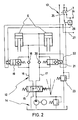
- a hydraulic line and valve system designated as a whole as 12 and its electrical control circuit 13 are shown schematically in FIG. 2.
- the hydraulic cylinders 14 connect the lifting cylinders 6 via a four / three-way valve 15, a lifting line 16 and a lowering line 17.
- a check valve 18 is arranged in the stroke line 16 and a two / two-way valve 19 is connected in parallel thereto.
- a check valve 20 and, in parallel, a two / two-way valve 21 are connected in the lowering line 17.
- a discharge line 22 branches off from the lowering line 17 between the valves and the reciprocating piston 6 and leads to a pressure limiting valve 23.
- the electrical control circuit 13 can be acted upon by the driving switch 7.
- a pulse line 24 is switched for the travel drive.
- the valves are actuated via a control member 25.
- a timer 26 is applied.
- Fig. 2 shows the rest position, i.e. the driving switch is not closed, the road construction machine is at a standstill. In this position, the two / two-way valve 19 in the lifting line 16 is closed. A return of the hydraulic fluid from the piston rod side of the cylinder to the hydraulic system is not possible, i.e. the lowering movement of the pistons and thus a change in position of the screed is blocked. The two / two-way valve 21 in the lowering line 17 is open.
- the driving switch 7 is brought into its closed position. It sets the travel drive in motion via the impulse line 24. At the same time, he switches on the control element 25. This in turn switches the two / two-way valve 21 in the lowering line into the blocking position. The lifting cylinders 6 are thus blocked in both directions of movement and thus the screed 2. Simultaneously with these switching operations, a leveling device (not shown), which controls the adjusting movements of the leveling cylinders 5, was blocked via a pulse line 27. All changes in position of the screed 2 are thus switched off during the start. Simultaneously with the switching of the driving switch, the timer 26 was applied.
- the timer 26 switches in the electrical control circuit 13 in such a way that both the two / two-way valve 19 and the two / two-way valve 21 are switched to free passage. So that the lifting cylinders 6 are released in both directions of movement, the screed is kept floating. At the same time, the blockage of the leveling cylinders is released via the impulse line 27.
- the switching operations described ensure that the screed, together with the booms 3 and the lifting cylinders 6, forms a system that is rigidly connected to the road construction machine 1 and does not allow any changes in height during a certain travel time of the road construction machine.
- the screed cannot be forcibly lifted by road construction material that has reached the screed before the road construction machine comes to a standstill and has lost its flowability during the standstill due to cooling. A height error in layer 9 is thus avoided.
- the subsequent simultaneous release of the leveling device and the lifting cylinder movement brings about a seamless transition to the normal working process.
- the invention is not restricted to the exemplary embodiment. It is essential that the height movement of the screed is automatically blocked during a certain travel time period and then automatically released again. The way this blockage and its control depends essentially on the design of the screed attachment and its actuation and control devices.
Priority Applications (1)
| Application Number | Priority Date | Filing Date | Title |
|---|---|---|---|
| AT86113678T ATE50010T1 (de) | 1985-10-03 | 1986-10-03 | Verfahren und vorrichtung zur hoehenregulierung einer nivellierungsbohle. |
Applications Claiming Priority (2)
| Application Number | Priority Date | Filing Date | Title |
|---|---|---|---|
| DE3535362 | 1985-10-03 | ||
| DE3535362A DE3535362C1 (de) | 1985-10-03 | 1985-10-03 | Verfahren und Vorrichtung zur Hoehenregulierung einer Nivellierungsbohle |
Publications (3)
| Publication Number | Publication Date |
|---|---|
| EP0217408A2 EP0217408A2 (de) | 1987-04-08 |
| EP0217408A3 EP0217408A3 (en) | 1987-10-28 |
| EP0217408B1 true EP0217408B1 (de) | 1990-01-31 |
Family
ID=6282695
Family Applications (1)
| Application Number | Title | Priority Date | Filing Date |
|---|---|---|---|
| EP86113678A Expired - Lifetime EP0217408B1 (de) | 1985-10-03 | 1986-10-03 | Verfahren und Vorrichtung zur Höhenregulierung einer Nivellierungsbohle |
Country Status (7)
| Country | Link |
|---|---|
| US (1) | US4759657A (zh) |
| EP (1) | EP0217408B1 (zh) |
| CN (1) | CN1007169B (zh) |
| AT (1) | ATE50010T1 (zh) |
| DE (2) | DE3535362C1 (zh) |
| ES (1) | ES2013231B3 (zh) |
| GR (1) | GR3000358T3 (zh) |
Families Citing this family (25)
| Publication number | Priority date | Publication date | Assignee | Title |
|---|---|---|---|---|
| DE3810891A1 (de) * | 1988-03-30 | 1989-10-19 | Heilit & Woerner Bau Ag | Tragschichtfertiger |
| US5046889A (en) * | 1989-12-05 | 1991-09-10 | Sterner Jr Carl L | Rolling screed spreader box |
| DE4040027A1 (de) * | 1990-12-14 | 1992-06-17 | Voegele Ag J | Verfahren zum einstellen der staerke einer einbauschicht mit einem strassenfertiger |
| US5569807A (en) * | 1992-05-01 | 1996-10-29 | Phillips Petroleum Company | Isoparaffin-olefin alkylation |
| FR2681886B1 (fr) * | 1991-09-30 | 1994-02-11 | Etat Francais Lab Ponts Chaussee | Procede et dispositif de mesure de l'epaisseur moyenne d'une couche de chaussee. |
| DE4211286C2 (de) * | 1992-04-03 | 2003-08-21 | Metso Dynapac Gmbh | Verfahren zum Arretieren einer Einbausohle eines Straßenfertigers und Straßenfertiger zur Durchführung des Verfahrens |
| DE9406683U1 (de) * | 1994-04-21 | 1994-06-30 | Voegele Ag J | Straßenfertiger |
| US5533828A (en) * | 1994-09-29 | 1996-07-09 | Astec Industries, Inc. | Method and apparatus for discharging paving materials on top of distributing auger |
| US5568992A (en) * | 1995-05-19 | 1996-10-29 | Caterpillar Paving Products Inc. | Screed control system for an asphalt paver and method of use |
| DE29520147U1 (de) * | 1995-12-19 | 1996-02-08 | Voegele Ag J | Gleitschalungsfertiger für den Betonbau |
| DE19647150C2 (de) * | 1996-11-14 | 2001-02-01 | Moba Mobile Automation Gmbh | Vorrichtung und Verfahren zum Steuern der Einbauhöhe eines Straßenfertigers |
| US5868522A (en) * | 1997-01-16 | 1999-02-09 | Astec Industries, Inc. | Vibratory screed assembly for an asphalt paving machine |
| DE19709131C2 (de) * | 1997-03-06 | 2003-02-20 | Abg Allg Baumaschinen Gmbh | Deckenfertiger |
| DE10155507B4 (de) * | 2001-11-13 | 2005-10-06 | Abg Allgemeine Baumaschinen-Gesellschaft Mbh | Fertiger zum bodenseitigen Einbau von Schichten für Straßen od. dgl. |
| EP1610874A4 (en) * | 2003-03-25 | 2008-04-23 | Somero Entpr Inc | DEVICE AND METHOD FOR BETTER CONTROL OF A CONCRETE DRAWER HEAD ASSEMBLY |
| US20050163565A1 (en) * | 2004-01-27 | 2005-07-28 | Quenzi Philip J. | Concrete-chute strike-off device |
| US8382395B2 (en) * | 2008-06-20 | 2013-02-26 | Caterpillar Inc. | Paving system and method for controlling compactor interaction with paving material mat |
| US7946787B2 (en) * | 2008-06-27 | 2011-05-24 | Caterpillar Inc. | Paving system and method |
| US20100196096A1 (en) * | 2009-02-02 | 2010-08-05 | Somero Enterprises, Inc. | Apparatus and method for improving the control of a concrete screeding machine |
| DE102009019839A1 (de) † | 2009-03-09 | 2010-09-16 | Bomag Gmbh | Hydraulische Steueranordnung für die Bohle eines Straßenfertigers |
| US9200415B2 (en) * | 2013-11-19 | 2015-12-01 | Caterpillar Paving Products Inc. | Paving machine with automatically adjustable screed assembly |
| ES2833472T3 (es) | 2014-04-28 | 2021-06-15 | Somero Entpr Inc | Sistema de nivelación de concreto con control/retroalimentación de la calidad del suelo |
| DE102016008253A1 (de) * | 2016-07-08 | 2018-01-11 | Dynapac Gmbh | Straßenfertiger und Verfahren zur Herstellung eines Straßenbelags |
| EP3728739B1 (en) | 2017-12-18 | 2023-11-08 | Somero Enterprises, Inc. | Concrete screeding machine with column block control using gyroscope sensor |
| US10472777B1 (en) * | 2018-05-02 | 2019-11-12 | Caterpillar Paving Products Inc. | Screed tow point assembly for paver |
Family Cites Families (3)
| Publication number | Priority date | Publication date | Assignee | Title |
|---|---|---|---|---|
| DE2333371C2 (de) * | 1973-06-30 | 1990-08-02 | Dynapac HOES GmbH, 2906 Wardenburg | Straßenfertiger |
| US4026658A (en) * | 1974-07-26 | 1977-05-31 | Barber-Greene Company | Automatic support system for a screed |
| SU975862A1 (ru) * | 1981-03-26 | 1982-11-23 | Proizv T I Dorozhnogo Str Latt | Устройство для управления положением выглаживающей плиты асфальтоукладчика 1 2 |
-
1985
- 1985-10-03 DE DE3535362A patent/DE3535362C1/de not_active Expired
-
1986
- 1986-09-29 CN CN86106861A patent/CN1007169B/zh not_active Expired
- 1986-10-02 US US06/914,450 patent/US4759657A/en not_active Expired - Fee Related
- 1986-10-03 DE DE8686113678T patent/DE3668651D1/de not_active Revoked
- 1986-10-03 ES ES86113678T patent/ES2013231B3/es not_active Expired - Lifetime
- 1986-10-03 EP EP86113678A patent/EP0217408B1/de not_active Expired - Lifetime
- 1986-10-03 AT AT86113678T patent/ATE50010T1/de not_active IP Right Cessation
-
1990
- 1990-02-26 GR GR90400105T patent/GR3000358T3/el unknown
Also Published As
| Publication number | Publication date |
|---|---|
| CN86106861A (zh) | 1987-04-29 |
| DE3668651D1 (de) | 1990-03-08 |
| EP0217408A3 (en) | 1987-10-28 |
| ATE50010T1 (de) | 1990-02-15 |
| US4759657A (en) | 1988-07-26 |
| CN1007169B (zh) | 1990-03-14 |
| GR3000358T3 (en) | 1991-06-07 |
| DE3535362C1 (de) | 1987-03-26 |
| EP0217408A2 (de) | 1987-04-08 |
| ES2013231B3 (es) | 1990-05-01 |
Similar Documents
| Publication | Publication Date | Title |
|---|---|---|
| EP0217408B1 (de) | Verfahren und Vorrichtung zur Höhenregulierung einer Nivellierungsbohle | |
| EP0309761B1 (de) | Schleppfahrzeug für Flugzeuge Schwenkantrieb Hubschaufel | |
| DE2009427C3 (de) | Gleisloser Straßenfertiger zum Verbreitern bereits vorhandener Straßendecken | |
| DE102007026527A1 (de) | Motor-Grader und Steuersystem dafür | |
| EP1703023A1 (de) | Tiefbauvorrichtung zum Herstellen von Schlitzen im Boden mit Lenk- und Steuereinrichtung | |
| DE2738771A1 (de) | Automatisches steuersystem fuer das arbeitswerkzeug eines arbeitsfahrzeuges | |
| DE112016000713B4 (de) | Auto-Kalibrierung eines automatischen Nivelliersteuersystems in einer Arbeitsmaschine | |
| DE3716260C1 (de) | Verfahren zur Justierung und Befestigung von Funktionsflaechen eines Fahrwegs einer elektromagnetischen Schnellbahn und Vorrichtung zur Durchfuehrung des Verfahrens | |
| DE10155507A1 (de) | Fertiger zum bodenseitigen Einbau von Schichten für Straßen od. dgl. | |
| DE2330548A1 (de) | Vorrichtung, die waehrend ihrer vorwaertsbewegung ein band aus einem formbaren plastischen gemisch legt | |
| DE2627845C2 (de) | Verfahren und Vorrichtung zum Setzen von Schwellen auf das Schotterbett eines Gleises | |
| CH625139A5 (en) | Apparatus for pivoting a spray nozzle to and fro about a pivot axis, in particular for spraying concrete | |
| EP1179636A1 (de) | Strassenfertiger und Einbauverfahren | |
| EP0102060B1 (de) | Vorrichtung zur selbsttätigen Regelung der Vorabstreiferhöhe eines Gleitschalungsfertigers | |
| CH658220A5 (de) | Fahrbare beton- oder gesteinsfraesmaschine. | |
| EP0335339B1 (de) | Tragschichtfertiger | |
| AT395877B (de) | Einrichtung zum aufrauhen und einebnen einer mit hartschnee bedeckten und/oder vereisten verkehrsflaeche | |
| EP0088140B1 (de) | Pflug mit einem am Pflugrahmen angebrachten Ausleger | |
| DE3427337A1 (de) | Einbaueinrichtung fuer schuettfaehige massen, insbesondere beton, zur herstellung von strassendecken, betonpisten oder dergleichen betonflaechen | |
| DE3921869C1 (en) | Compact loader for road surfacing machine - has powered cold grinder, hydraulic pumps and manual control lever | |
| DE3325991A1 (de) | Automatische schneidmaschine fuer asphaltierte strassenflaechen | |
| EP0104441B1 (de) | Dübel-Setzgerät | |
| DE3123126C2 (zh) | ||
| DD201924A5 (de) | Gleisstopfungsmaschine | |
| DE3111323A1 (de) | "gleichlaufueberwachungsvorrichtung, insbesondere fuer hebebuehnen" |
Legal Events
| Date | Code | Title | Description |
|---|---|---|---|
| PUAI | Public reference made under article 153(3) epc to a published international application that has entered the european phase |
Free format text: ORIGINAL CODE: 0009012 |
|
| AK | Designated contracting states |
Kind code of ref document: A2 Designated state(s): AT BE CH DE ES FR GB GR IT LI NL SE |
|
| PUAL | Search report despatched |
Free format text: ORIGINAL CODE: 0009013 |
|
| AK | Designated contracting states |
Kind code of ref document: A3 Designated state(s): AT BE CH DE ES FR GB GR IT LI NL SE |
|
| 17P | Request for examination filed |
Effective date: 19880427 |
|
| 17Q | First examination report despatched |
Effective date: 19890306 |
|
| GRAA | (expected) grant |
Free format text: ORIGINAL CODE: 0009210 |
|
| AK | Designated contracting states |
Kind code of ref document: B1 Designated state(s): AT BE CH DE ES FR GB GR IT LI NL SE |
|
| REF | Corresponds to: |
Ref document number: 50010 Country of ref document: AT Date of ref document: 19900215 Kind code of ref document: T |
|
| GBT | Gb: translation of ep patent filed (gb section 77(6)(a)/1977) | ||
| REF | Corresponds to: |
Ref document number: 3668651 Country of ref document: DE Date of ref document: 19900308 |
|
| ET | Fr: translation filed | ||
| ITF | It: translation for a ep patent filed |
Owner name: BUGNION S.P.A. |
|
| PGFP | Annual fee paid to national office [announced via postgrant information from national office to epo] |
Ref country code: GR Payment date: 19900809 Year of fee payment: 5 |
|
| PLBI | Opposition filed |
Free format text: ORIGINAL CODE: 0009260 |
|
| PGFP | Annual fee paid to national office [announced via postgrant information from national office to epo] |
Ref country code: GB Payment date: 19900924 Year of fee payment: 5 |
|
| PGFP | Annual fee paid to national office [announced via postgrant information from national office to epo] |
Ref country code: FR Payment date: 19901009 Year of fee payment: 5 |
|
| 26 | Opposition filed |
Opponent name: ABG-WERKE GMBH Effective date: 19900811 |
|
| PGFP | Annual fee paid to national office [announced via postgrant information from national office to epo] |
Ref country code: ES Payment date: 19901011 Year of fee payment: 5 Ref country code: AT Payment date: 19901011 Year of fee payment: 5 |
|
| PGFP | Annual fee paid to national office [announced via postgrant information from national office to epo] |
Ref country code: BE Payment date: 19901015 Year of fee payment: 5 |
|
| PGFP | Annual fee paid to national office [announced via postgrant information from national office to epo] |
Ref country code: SE Payment date: 19901018 Year of fee payment: 5 |
|
| ITTA | It: last paid annual fee | ||
| PGFP | Annual fee paid to national office [announced via postgrant information from national office to epo] |
Ref country code: NL Payment date: 19901031 Year of fee payment: 5 |
|
| NLR1 | Nl: opposition has been filed with the epo |
Opponent name: ABG-WERKE GMBH |
|
| PGFP | Annual fee paid to national office [announced via postgrant information from national office to epo] |
Ref country code: CH Payment date: 19901123 Year of fee payment: 5 |
|
| PGFP | Annual fee paid to national office [announced via postgrant information from national office to epo] |
Ref country code: DE Payment date: 19901130 Year of fee payment: 5 |
|
| RDAG | Patent revoked |
Free format text: ORIGINAL CODE: 0009271 |
|
| STAA | Information on the status of an ep patent application or granted ep patent |
Free format text: STATUS: PATENT REVOKED |
|
| 27W | Patent revoked |
Effective date: 19910809 |
|
| REG | Reference to a national code |
Ref country code: CH Ref legal event code: PL |
|
| GBPR | Gb: patent revoked under art. 102 of the ep convention designating the uk as contracting state | ||
| NLR2 | Nl: decision of opposition | ||
| BERE | Be: lapsed |
Owner name: JOSEPH VOGELE A.G. Effective date: 19911031 |
|
| REG | Reference to a national code |
Ref country code: GR Ref legal event code: MF4A Free format text: 3000358 |
|
| EUG | Se: european patent has lapsed |
Ref document number: 86113678.6 Effective date: 19911227 |
|
| PLAB | Opposition data, opponent's data or that of the opponent's representative modified |
Free format text: ORIGINAL CODE: 0009299OPPO |