EP0215358B1 - Verfahren und Vorrichtung mit Ein- und Ausgangsbehandlungskammern zum Laminieren unter reduziertem Druck - Google Patents
Verfahren und Vorrichtung mit Ein- und Ausgangsbehandlungskammern zum Laminieren unter reduziertem Druck Download PDFInfo
- Publication number
- EP0215358B1 EP0215358B1 EP86111989A EP86111989A EP0215358B1 EP 0215358 B1 EP0215358 B1 EP 0215358B1 EP 86111989 A EP86111989 A EP 86111989A EP 86111989 A EP86111989 A EP 86111989A EP 0215358 B1 EP0215358 B1 EP 0215358B1
- Authority
- EP
- European Patent Office
- Prior art keywords
- chamber device
- gate valve
- staging chamber
- printed circuit
- input
- Prior art date
- Legal status (The legal status is an assumption and is not a legal conclusion. Google has not performed a legal analysis and makes no representation as to the accuracy of the status listed.)
- Expired - Lifetime
Links
- 238000000034 method Methods 0.000 title abstract description 26
- 238000009824 pressure lamination Methods 0.000 title abstract description 5
- 238000003475 lamination Methods 0.000 claims description 69
- 239000000463 material Substances 0.000 abstract description 20
- 239000010408 film Substances 0.000 description 29
- 238000010030 laminating Methods 0.000 description 15
- 238000010276 construction Methods 0.000 description 10
- 238000007789 sealing Methods 0.000 description 8
- 230000001681 protective effect Effects 0.000 description 2
- 239000010409 thin film Substances 0.000 description 2
- 238000004804 winding Methods 0.000 description 2
- 230000037303 wrinkles Effects 0.000 description 2
- 230000000740 bleeding effect Effects 0.000 description 1
- 238000000605 extraction Methods 0.000 description 1
- 238000010438 heat treatment Methods 0.000 description 1
- 238000003825 pressing Methods 0.000 description 1
- 238000005086 pumping Methods 0.000 description 1
- 230000000717 retained effect Effects 0.000 description 1
- 238000004544 sputter deposition Methods 0.000 description 1
Images


Classifications
-
- G—PHYSICS
- G03—PHOTOGRAPHY; CINEMATOGRAPHY; ANALOGOUS TECHNIQUES USING WAVES OTHER THAN OPTICAL WAVES; ELECTROGRAPHY; HOLOGRAPHY
- G03F—PHOTOMECHANICAL PRODUCTION OF TEXTURED OR PATTERNED SURFACES, e.g. FOR PRINTING, FOR PROCESSING OF SEMICONDUCTOR DEVICES; MATERIALS THEREFOR; ORIGINALS THEREFOR; APPARATUS SPECIALLY ADAPTED THEREFOR
- G03F7/00—Photomechanical, e.g. photolithographic, production of textured or patterned surfaces, e.g. printing surfaces; Materials therefor, e.g. comprising photoresists; Apparatus specially adapted therefor
- G03F7/16—Coating processes; Apparatus therefor
-
- B—PERFORMING OPERATIONS; TRANSPORTING
- B32—LAYERED PRODUCTS
- B32B—LAYERED PRODUCTS, i.e. PRODUCTS BUILT-UP OF STRATA OF FLAT OR NON-FLAT, e.g. CELLULAR OR HONEYCOMB, FORM
- B32B37/00—Methods or apparatus for laminating, e.g. by curing or by ultrasonic bonding
- B32B37/14—Methods or apparatus for laminating, e.g. by curing or by ultrasonic bonding characterised by the properties of the layers
- B32B37/16—Methods or apparatus for laminating, e.g. by curing or by ultrasonic bonding characterised by the properties of the layers with all layers existing as coherent layers before laminating
- B32B37/22—Methods or apparatus for laminating, e.g. by curing or by ultrasonic bonding characterised by the properties of the layers with all layers existing as coherent layers before laminating involving the assembly of both discrete and continuous layers
- B32B37/223—One or more of the layers being plastic
- B32B37/226—Laminating sheets, panels or inserts between two continuous plastic layers
-
- B—PERFORMING OPERATIONS; TRANSPORTING
- B32—LAYERED PRODUCTS
- B32B—LAYERED PRODUCTS, i.e. PRODUCTS BUILT-UP OF STRATA OF FLAT OR NON-FLAT, e.g. CELLULAR OR HONEYCOMB, FORM
- B32B38/00—Ancillary operations in connection with laminating processes
- B32B38/18—Handling of layers or the laminate
- B32B38/1825—Handling of layers or the laminate characterised by the control or constructional features of devices for tensioning, stretching or registration
- B32B38/1833—Positioning, e.g. registration or centering
- B32B38/1841—Positioning, e.g. registration or centering during laying up
- B32B38/185—Positioning, e.g. registration or centering during laying up combined with the cutting of one or more layers
-
- G—PHYSICS
- G03—PHOTOGRAPHY; CINEMATOGRAPHY; ANALOGOUS TECHNIQUES USING WAVES OTHER THAN OPTICAL WAVES; ELECTROGRAPHY; HOLOGRAPHY
- G03F—PHOTOMECHANICAL PRODUCTION OF TEXTURED OR PATTERNED SURFACES, e.g. FOR PRINTING, FOR PROCESSING OF SEMICONDUCTOR DEVICES; MATERIALS THEREFOR; ORIGINALS THEREFOR; APPARATUS SPECIALLY ADAPTED THEREFOR
- G03F7/00—Photomechanical, e.g. photolithographic, production of textured or patterned surfaces, e.g. printing surfaces; Materials therefor, e.g. comprising photoresists; Apparatus specially adapted therefor
-
- H—ELECTRICITY
- H05—ELECTRIC TECHNIQUES NOT OTHERWISE PROVIDED FOR
- H05K—PRINTED CIRCUITS; CASINGS OR CONSTRUCTIONAL DETAILS OF ELECTRIC APPARATUS; MANUFACTURE OF ASSEMBLAGES OF ELECTRICAL COMPONENTS
- H05K3/00—Apparatus or processes for manufacturing printed circuits
- H05K3/22—Secondary treatment of printed circuits
- H05K3/28—Applying non-metallic protective coatings
- H05K3/281—Applying non-metallic protective coatings by means of a preformed insulating foil
-
- B—PERFORMING OPERATIONS; TRANSPORTING
- B29—WORKING OF PLASTICS; WORKING OF SUBSTANCES IN A PLASTIC STATE IN GENERAL
- B29C—SHAPING OR JOINING OF PLASTICS; SHAPING OF MATERIAL IN A PLASTIC STATE, NOT OTHERWISE PROVIDED FOR; AFTER-TREATMENT OF THE SHAPED PRODUCTS, e.g. REPAIRING
- B29C2791/00—Shaping characteristics in general
- B29C2791/004—Shaping under special conditions
- B29C2791/006—Using vacuum
-
- B—PERFORMING OPERATIONS; TRANSPORTING
- B29—WORKING OF PLASTICS; WORKING OF SUBSTANCES IN A PLASTIC STATE IN GENERAL
- B29L—INDEXING SCHEME ASSOCIATED WITH SUBCLASS B29C, RELATING TO PARTICULAR ARTICLES
- B29L2031/00—Other particular articles
- B29L2031/34—Electrical apparatus, e.g. sparking plugs or parts thereof
- B29L2031/3425—Printed circuits
-
- B—PERFORMING OPERATIONS; TRANSPORTING
- B32—LAYERED PRODUCTS
- B32B—LAYERED PRODUCTS, i.e. PRODUCTS BUILT-UP OF STRATA OF FLAT OR NON-FLAT, e.g. CELLULAR OR HONEYCOMB, FORM
- B32B2309/00—Parameters for the laminating or treatment process; Apparatus details
- B32B2309/60—In a particular environment
- B32B2309/68—Vacuum
-
- H—ELECTRICITY
- H05—ELECTRIC TECHNIQUES NOT OTHERWISE PROVIDED FOR
- H05K—PRINTED CIRCUITS; CASINGS OR CONSTRUCTIONAL DETAILS OF ELECTRIC APPARATUS; MANUFACTURE OF ASSEMBLAGES OF ELECTRICAL COMPONENTS
- H05K2203/00—Indexing scheme relating to apparatus or processes for manufacturing printed circuits covered by H05K3/00
- H05K2203/06—Lamination
- H05K2203/068—Features of the lamination press or of the lamination process, e.g. using special separator sheets
-
- H—ELECTRICITY
- H05—ELECTRIC TECHNIQUES NOT OTHERWISE PROVIDED FOR
- H05K—PRINTED CIRCUITS; CASINGS OR CONSTRUCTIONAL DETAILS OF ELECTRIC APPARATUS; MANUFACTURE OF ASSEMBLAGES OF ELECTRICAL COMPONENTS
- H05K2203/00—Indexing scheme relating to apparatus or processes for manufacturing printed circuits covered by H05K3/00
- H05K2203/08—Treatments involving gases
- H05K2203/085—Using vacuum or low pressure
-
- Y—GENERAL TAGGING OF NEW TECHNOLOGICAL DEVELOPMENTS; GENERAL TAGGING OF CROSS-SECTIONAL TECHNOLOGIES SPANNING OVER SEVERAL SECTIONS OF THE IPC; TECHNICAL SUBJECTS COVERED BY FORMER USPC CROSS-REFERENCE ART COLLECTIONS [XRACs] AND DIGESTS
- Y10—TECHNICAL SUBJECTS COVERED BY FORMER USPC
- Y10T—TECHNICAL SUBJECTS COVERED BY FORMER US CLASSIFICATION
- Y10T156/00—Adhesive bonding and miscellaneous chemical manufacture
- Y10T156/10—Methods of surface bonding and/or assembly therefor
- Y10T156/1052—Methods of surface bonding and/or assembly therefor with cutting, punching, tearing or severing
-
- Y—GENERAL TAGGING OF NEW TECHNOLOGICAL DEVELOPMENTS; GENERAL TAGGING OF CROSS-SECTIONAL TECHNOLOGIES SPANNING OVER SEVERAL SECTIONS OF THE IPC; TECHNICAL SUBJECTS COVERED BY FORMER USPC CROSS-REFERENCE ART COLLECTIONS [XRACs] AND DIGESTS
- Y10—TECHNICAL SUBJECTS COVERED BY FORMER USPC
- Y10T—TECHNICAL SUBJECTS COVERED BY FORMER US CLASSIFICATION
- Y10T156/00—Adhesive bonding and miscellaneous chemical manufacture
- Y10T156/12—Surface bonding means and/or assembly means with cutting, punching, piercing, severing or tearing
- Y10T156/1317—Means feeding plural workpieces to be joined
- Y10T156/1343—Cutting indefinite length web after assembly with discrete article
Definitions
- the invention refers to a device for applying a light sensitive film onto a surface of a printed circuit base board, as described in the general clause of the claims 1 and 2.
- the reference numerals 1 denote parallel and mutually contacting rollers, constructed to have resilient outer surfaces as by being covered with rubber or the like, which rotate in the directions as shown in the figure by the arrows "b", and which form a mutual gas tight pressure seal by being pressed together as well as forming gas tight pressure seals by being pressed against a wall 3 of a reduced pressure chamber on either side of a slot 3a formed in said wall 3, said slot 3a leading to the interior of said reduced pressure chamber (not otherwise shown).
- a base board 2 for lamination is fed in the direction indicated by the arrow "a" in the figure through between said rollers 1 and then through the slot 3a into the interior of the reduced pressure chamber 3 which is being maintained at a pressure substantially lower than atmospheric pressure, while still the gas tight pressure seal provided between said rollers 1 is substantially maintained due to the resilience of the material of said rollers 1.
- rollers 1 are similarly constructed to have resilient outer surfaces as by being covered with rubber or the like and similarly still form a mutual gas tight pressure seal by being pressed together, are not pressed against the wall 3 of the reduced pressure chamber, but rather relatively small gaps are left between said rollers 1 and said reduced pressure chamber wall 3.
- constructions comprising bases 5, to which sealing strips 4 are retained by being fixed by retaining bars 6 and fixing bolts 7.
- the sealing strips 4 are pressed against the outer sides of the rollers 1 in the trailing direction with regard to the rotation of said rollers 1 in the directions indicated by the arrows "b", and are sucked inwards by the reduced pressure in the laminating chamber (to the left in the figure of the wall 3), so as to form good and effective seals against the outer sides of said rollers 1.
- the base board 2 for lamination is fed in the direction indicated by the arrow "a" in the figure through between said rollers 1 and then through the slot 3a into the interior of the reduced pressure chamber 3 which is being maintained at a pressure substantially lower than atmospheric pressure, while still the gas tight pressure seal provided between said rollers 1 is substantially maintained due to the resilience of the material of said rollers 1, as the base board 2 nevertheless passes between said rollers 1.
- the above-mentioned devices are not appropriate to handle those thick base boards and particularly not at higher vacuum.
- US-A-4 405 435 shows a sputtering apparatus or a similar apparatus in which the flow rate of a gas intake, the leakage through gaps in the inlet and outlet of gas-filled treatment chambers and the evacuating rate of a vacuum pump are coordinated in such a way that a certain pressure level lower than that of the environment air is maintained.
- This device requires a vacuum pump of high capability.
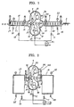
- Fig. 1 is a schematic longitudinal sectional view showing the first preferred embodiment of the reduced pressure laminating device according to the present invention.
- the reference numeral 2 denotes a board such as a printed circuit base board, which is to be laminated by this apparatus together with a light sensitive thin film material, and which is fed through, in turn, an input staging chamber device 8, a main lamination chamber device 9, and an output staging chamber device 10.
- input and output staging chamber devices 8 and 10 function as air locks for maintaining the reduced pressure in the main lamination chamber device 9 at an acceptably low level without any requirement for heavy duty operation of a vacuum pump.
- an input staging chamber device input gate valve 14 leading into the input staging chamber device 8 is opened, while an input staging chamber device output gate valve 15 leading out from said input staging chamber device 8 into the main lamination chamber device 9 is closed; and, furthermore, an input staging chamber device bleed valve 23 is opened, while an input staging chamber device evacuation valve 11 is closed.
- the board 2 is passed through the input staging chamber device input gate valve 14 and is received into the internal cavity of the input staging chamber device 8.
- the gate valves such as the input staging chamber device input gate valve 14 and the input staging chamber device output gate valve 15 may be of a type described hereinafter, as may other gate valves which will be described shortly.
- the board 2 is supplied individually; in other words boards are not taken in to the device in plurality as is the case with the second preferred method and device embodiments to be described subsequently.
- the input staging chamber device input gate valve 14 is closed, while the input staging chamber device output gate valve 15 leading out from said input staging chamber device 8 into the main lamination chamber device 9 is maintained as closed; and now the input staging chamber device bleed valve 23 is closed, while the input staging chamber device evacuation valve 11 is opened and also a vacuum pump 31 is operated.
- the internal cavity of the input staging chamber device 8 holding the board 2 in it is isolated from the ambient atmosphere and also from the main lamination chamber device 9, while the vacuum pump 31, via a conduit system not denoted by any reference numeral, sucks out the atmospheric air within said internal cavity of said input staging chamber device 8, thus to bring the pressure in said internal cavity and surrounding the base board 2 down to an appropriate reduced pressure for performing lamination.
- the pressure in the input staging chamber device 8 is monitored by the use of a per se conventional pressure metering device 22 which has contacts which close at a determinate pressure level, or the like.
- the board 2 is forwarded by a plurality of transport rollers 20 from the internal cavity of the input staging chamber device 8 through the input staging chamber device output gate valve 15 into the main lamination chamber device 9. As this occurs, the board 2 is preheated by heater rollers 28 in said main lamination chamber device 9, in between which rollers 28 said board 2 passes.
- the board 2 in the internal cavity of the main lamination chamber device 9, is forwarded in between laminating rollers 26, and is laminated to a sheet 44 of thin film light sensitive material (or the like), which is transported while being preheated by a heating shoe 33 from a protection film winding shaft 30, with the aid of a light sensitive material extraction roller 29.
- the reference numeral 32 denotes a pressure cylinder for pressing the two laminating rollers 26 together. And, as the board 2 laminated with the light sensitive film material is further transported, said light sensitive film material is cut by a cutter 27.
- the input staging chamber device output gate valve 15 is now closed, so as to isolate the input staging chamber device 8 from the main lamination chamber device 9.
- the input staging chamber device bleed valve 23 is opened so as gradually to leak air from «he ambient atmosphere into said input staging chamber device 8, so as to progressively bring its internal pressure up to atmospheric.
- the input staging chamber device input gate valve 14 may be opened, to repeat the cycle of inputting for the next printed circuit board 2 to be laminated, as described above, while the input staging chamber device output gate valve 15 is maintained as closed.
- the printed circuit board 2 now laminated with the thin light sensitive film material is forwarded by a plurality of transport rollers 21 from the internal cavity of the main lamination chamber device 9 into the output staging chamber device 10 through said output staging chamber device input gate valve 16.
- this taking out of the laminated printed circuit board 2 is performed one board at a time.
- the length of the printed circuit board 2 is less than the distance between the cutter 27 and the output staging chamber device input gate valve 16, then the thin pressure sensitive film may be cut by said cutter 27 before said output staging chamber device input gate valve 16 is opened; otherwise, it will be necessary to cut the thin pressure sensitive film by said cutter 27 while the printed circuit board 2 with the film laminated thereto is being passed through the opened output staging chamber device input gate valve 16.
- the output staging chamber device input gate valve 16 is now closed, so as to isolate the output staging chamber device 10 from the main lamination chamber device 9.
- the output staging chamber device bleed valve 25 is opened so as gradually to leak air from the ambient atmosphere into said output staging chamber device 10, so as to progressively bring its internal pressure up to atmospheric.
- the output staging chamber device bleed valve 25 is maintained as closed.
- the output staging chamber device output gate valve 17 is opened.
- the board 2 is further fed by the rollers 21 in the leftwards direction as seen in the figure, through the opened output staging chamber device output gate valve 17 to the outside, while the output staging chamber device input gate valve 16 leading out from the main lamination chamber device 9 into said output staging chamber device 10 is kept closed; and, furthermore, the output staging chamber device evacuation valve 13 is kept closed.
- the board 2 is passed from the internal cavity of the output staging chamber device 10 through the output staging chamber device output gate valve 17 to the outside for further processing.
- the output staging chamber device output gate valve 17 is closed, while the output staging chamber device input gate valve 16 leading in to said output staging chamber device 10 from the main lamination chamber device 9 is maintained as similarly closed; and now the output staging chamber device bleed valve 25 is closed, while the output staging chamber device evacuation valve 13 is opened and also the vacuum pump 31 is operated.
- the internal cavity of the output staging chamber device 10 (which is currently empty) is isolated from the ambient atmosphere and also from the main lamination chamber device 9, while the vacuum pump 31, via the conduit system not denoted by any reference numeral, sucks out the atmospheric air within said internal cavity of said output staging chamber device 10, thus to bring the pressure in said internal cavity down to be substantially equal to the appropriate reduced pressure for performing lamination within the main lamination chamber device 9.
- the pressure in said output staging chamber device 10 is monitored by the use of a per se conventional pressure metering device, not denoted by any reference numeral but similar to the device 22 on the input side, which similarly has contacts which close at a determinate pressure level or the like. And then this output staging chamber device 10 is ready for the next cycle of receiving a printed circuit board 2 with laminated light sensitive film thereon and transferring it to the outside.
- the spacings between the transport rollers 20 of the input staging chamber device 8, the preheating rollers 28 and the laminating rollers 26 of the main lamination chamber device 9, and the transport rollers 21 of the output staging chamber device 10, are adjusted beforehand according to the thickness of the base board 2.
- the spacing of these rollers is preferably adjusted to be about 1.6 mm greater than the thickness of the board 2.
- the reference numeral 12 denotes a main chamber evacuation valve.
- this main chamber evacuation valve 12 When this main chamber evacuation valve 12 is closed as is normally the case, vacuum (pressure depression) within the main lamination chamber device 9 is held therein and maintained. However, should it become necessary to evacuate further said main lamination chamber device 9, i.e. to drop the pressure therein, and of course when initially evacuating said main lamination chamber device 9, this main chamber evacuation valve 12 is opened, and simultaneously the vacuum pump 31 is operated, thus pumping air out of said main lamination chamber device 9 and reducing the pressure therein to an acceptable pressure level for lamination.
- FIG. 2 the second preferred embodiment of the reduced pressure laminating device according to the present invention will be described.
- reference numerals corresponding to reference numerals in Fig. 1 denote like parts.
- the input staging chamber device 8 and the output staging chamber device 10 are constructed to incorporate stocker devices 18 and 19.
- the stocker device 18 receives the base boards to be laminated and automatically supplies them one by one into the main lamination chamber device 9, for lamination therein.
- the other stocker device 19 receives the base boards which have been laminated with light sensitive film.
- These stocker devices 18 and 19 are opening and closing door constructions respectively for inserting and taking out the boards.
- Fig. 3 shows an example of a mechanism for adjusting the spacing of the base board preheating rollers 28 in the main lamination chamber device 9 of the first and second preferred embodiment devices shown in Figs. 1 and 2.
- the reference numeral 34 denotes a spacing adjustment knob, while 35 is a fitting for it, 36 is a bearing, 37 is a slide shaft, 38 is a roller support, and 39 is a main container frame.
- the spacing adjustment knob 34 By turning the spacing adjustment knob 34, the base board preheating roller 28 can be moved up and down at will, and the spacing between the rollers 28 can be set arbitrarily.
- the operation of this device will be clear to one of ordinary skill in the mechanical art without further explanation, in the light of this disclosure.
- the lamination and adhesion within the main lamination chamber device 9 may be carried out by using a hot roller lined with a heat resistant rubber or rubber like material capable of being heated up to approximately 100°C by the use of a sheath heater or the like without damage.
- a hot roller lined with a heat resistant rubber or rubber like material capable of being heated up to approximately 100°C by the use of a sheath heater or the like without damage.
- the method of carrying out lamination and adhesion with a rubber lined cold roller is also acceptable.
- the gate valves utilized in the device of the present invention may be conventional seal roller constructions such as those disclosed in the preamble to this specification, or may be of the type shown in detail in Figs. 4a and 4b.
- Fig. 4a is a transverse sectional view of such a gate valve
- Fig. 4b is a partial front elevation thereof.
- the reference numeral 40 denotes an air cylinder for raising and lowering a gate denoted by 42
- 41 is a frame for the gate valve
- 43 is a seal plate.
- Figs. 1 and 2 there are shown devices including cutters for the film after it has been adhered to the printed circuit base board 2, but this is not to be considered as limitative of the present invention; it is alternatively possible for the film to be cut to the dimensions of the printed circuit board 2 and then subsequently to be stuck on to said printed circuit board 2 in the main lamination chamber device 9 without being further cut.
- Such a structure is, for example, disclosed in Japanese Patent Laying Open Publication Serial No. 59-105256 (1984).
- this publication there is disclosed a mechanism whereby the film is cut to the dimensions of the printed circuit board and then is laminated and adhered to said printed circuit board.
- the adhesion is performed vertically, but when using the present invention with this mechanism being incorporated, it is preferable for the intake and exit containers to be above and below the main container respectively.
- the precut film may be stored permanently inside the main container, or alternatively it may be supplied along with the printed circuit boards through the intake container.
- the film may not necessarily be cut to exactly the same size as the printed circuit board; generally, in fact, the film is cut to be slightly smaller than the printed circuit board, but alternatively it could be larger.
- the film further has a protective film, but this is not necessary to the present invention, and in such a case the protective film winding roller or rollers 30 could be omitted.
- the benefit of the present invention is that it is possible to satisfactorily perform adhesion of a light sensitive film material under reduced pressure conditions to a base board of thickness 35 to 10 mm, which as explained above is a substantially thicker type of base board than could conveniently be handled by prior art laminating methods and devices. During such adhesion and lamination according to the present invention, there is no substantial risk of generation of air bubbles or wrinkles or the like. Furthermore, a higher vacuum value than available by the prior art can be utilized, for example a pressure of 0.04 bar (0.97 bar below atmospheric).
- a base printed circuit board about 8 mm in thickness (with printed circuit thickness about 75 microns) and about 330 mm by about 500 mm in size, was, at a feed speed of about 2 meters per minute, laminated and adhered to a light sensitive film material, so called Photek PHT-SR-1000N-75 (product name, manufactured by Hitachi Kasei Kogyo KK), with the intake container pressure of about 0.04 bar and with the intake container gate valve open.
Landscapes
- Engineering & Computer Science (AREA)
- Manufacturing & Machinery (AREA)
- Microelectronics & Electronic Packaging (AREA)
- Physics & Mathematics (AREA)
- General Physics & Mathematics (AREA)
- Lining Or Joining Of Plastics Or The Like (AREA)
- Manufacturing Of Printed Circuit Boards (AREA)
- Fluid-Pressure Circuits (AREA)
- Laminated Bodies (AREA)
- Manufacturing Of Printed Wiring (AREA)
- Casting Or Compression Moulding Of Plastics Or The Like (AREA)
Claims (2)
dadurch gekennzeichnet, daß eine Filmzuführeinrichtung (29, 30, 33, 26, 27) in der Hauptlaminierungskammer (9) angeordnet und von dieser vollständig umgeben ist für die Zuführung eines lichtempfindlichen Films (44) zur gedruckten Schaltungsgrundplatte (2), die in die Hauptlaminierungskammer transportiert worden ist, so daß der Film auf der Oberfläche der Grundplatte aufgebracht wird, um fest daran zu haften, und die Transportmittel (20, 28, 27, 21 die ersten bis vierten Absperrschieber (14,15,16,17), die ersten bis dritten Evakuiereinrichtungen (31, 11, 12, 13) und die Filmzuführeinrichtungen (29, 30, 33, 26, 27) im Zusammenwirken miteinander derart betrieben werden, daß in einem ersten Betriebsstadium der erste Absperrschieber (14) geöffnet ist, der zweite Absperrschieber (15) geschlossen ist, und die Transportmittel (20) eine gedruckte Schaltungsgrundplatte vollständig von außen in die Eingangsstufenkammer (8) über den ersten Absperrschieber (16) transportieren, in einem zweiten, darauf folgenden Betriebsstadium der erste Absperrschieber (14) geschlossen ist, und die erste Evakuiereinrichtung (31, 11) das Innere der Eingangsstufenkammer (8) evakuiert, in einem dritten, dem zweiten Betriebsstadium folgenden Betriebsstadium der zweite Absperrschieber (15) geöffnet wird, die Transportmittel (20,28) die gedruckte Schaltungsgrundplatte aus der Eingangsstufenkammer (8) vollständig in die Hauptlaminierungskammer (9) transportieren, die zweite Evakuiereinrichtung (31,12) das Innere der Hauptlaminierungskammer (9) evakuiert, wobei der dritte Absperrschieber (16) geschlossen ist, und die Filmzuführeinrichtung (29, 30, 33, 26, 27) den lichtempfindlichen Film (44) auf die gedruckte Schaltungsgrundplatte aufbringt, in einem vierten, dem dritten Betriebsstadium folgenden Betriebsstadium die dritte Evakuiereinrichtung (31, 13) das Innere der Ausgangsstufenkammer (10) evakuiert, wobei der vierte Absperrschieber (17) geschlossen ist, der dritte Absperrschieber (16) geöffnet ist und die Transportmittel (28, 27, 21) die gedruckte Schaltungsgrundplatte mit dem daran angebrachten lichtempfindlichen Film (44) von der Hauptlaminierungskammer (9) vollständig in die Ausgangsstufenkammer (10) transportiert, und einem fünften Betriebsstadium der dritte Absperrschieber (16) geschlossen ist, der vierte Absperrschieber (17) geöffnet ist, und die Transportmittel (21) die gedruckte Schaltungsgrundplatte mit dem daran angebrachten lichtempfindlichen Film von der Ausgangsstufenkammer (10) nach außen transportiert.
dadurch gekennzeichnet, daß eine Filmzuführeinrichtung (29, 30, 33, 26, 27) in der Hauptlaminierungskammer (9) angeordnet und vollständig von dieser umschlossen ist für die Zuführung eines lichtempfindlichen Films (44) zur gedruckten Schaltungsgrundplatte (2), die in die Hauptlaminierungskammer transportiert wurde zum Zweck der fest haftenden Aufbringung des Films auf der Oberfläche der Grundplatte, wobei die Eingangsstufenkammer (18) eine erste Stapeleinrichtung für die Aufnahme eines Stapels der gedruckten, mit einem lichtempfindlichen Film zu versehenen Schaltungsgrundplatten umfaßt, und die eine der Platten nach der anderen zum Ausgang der Eingangsstufenkammer leitet, und daß die Ausgangsstufenkammer (19) eine zweite Stapeleinrichtung zur Aufnahme eines Stapels von mit lichtempfindlichen Filmen versehenen gedruckten Schaltungsgrundplatten vom Eingang der Ausgangsstufenkammer umfaßt, wobei die Transportmittel (28, 26) die ersten und zweiten Absperrschieber (15, 16), die ersten bis dritten Evakuiereinrichtungen (31, 11, 12, 13) und die Filmzuführeinrichtung (29, 30, 33, 26, 28) derart in Beziehung zueinander betrieben werden, daß in einem ersten Betriebsstadium der erste Absperrschieber (15) geschlossen ist, die Eingangsstufenkammer (18) geladen wird mit einem Stapel von gedruckten Schaltungsgrundplatten und die erste Evakuiereinrichtung (31, 11) das Innere der Eingangsstufenkammer evakuiert, in einem zweiten, darauf folgenden Betriebsstadium der erste Absperrschieber (15) geöffnet ist, die Transportmittel eine gedruckte Schaltungsgrundplatte nach der anderen unter Entnahme von der ersten Stapelvorrichtung von der Eingangsstufenkammer (18) vollständig in die Hauptlaminierungskammer (9) transportieren, die zweite Evakuiereinrichtung (31, 12) das Innere der Hauptlaminierungskammer (9) evakuiert, wobei der zweite Absperrschieber (16) geschlossen ist, und die Filmzuführeinrichtung (29, 30, 33, 26, 27) den lichtempfindlichen Film (44) auf die gedruckte Schaltungsgrundplatte aufbringt, in einer dritten, dem zweiten Betriebsstadium folgenden Betriebsstadium die dritte Evakuiereinrichtung (31, 13) das Innere der Ausgangskammer (19) evakuiert, in einem vierten, dem dritten Betriebsstadium folgenden Betriebsstadium der zweite Absperrschieber (16) geöffnet ist, und die Transportmittel (28, 26) die mit einem lichtempfindlichen Film versehene gedruckte Schaltungsgrundplatte von der Hauptlaminierungskammer (9) vollständig in die Ausgangsstufenkammer (19) zum Zweck der Beschickung der zweiten Stapeleinrichtung transportiert, und in einem fünften, dem vierten Betriebsstadium folgenden Betriebsstadium der zweite Absperrschieber (16) geschlossen ist, und die gedruckten Schaltungsgrundplatten entfernt werden durch Entnahme von der zweiten Stapeleinrichtung in der Ausgangsstufenkammer in die Umgebung.
Priority Applications (1)
| Application Number | Priority Date | Filing Date | Title |
|---|---|---|---|
| AT86111989T ATE60733T1 (de) | 1985-08-30 | 1986-08-29 | Verfahren und vorrichtung mit ein- und ausgangsbehandlungskammern zum laminieren unter reduziertem druck. |
Applications Claiming Priority (2)
| Application Number | Priority Date | Filing Date | Title |
|---|---|---|---|
| JP60192789A JPS6252552A (ja) | 1985-08-30 | 1985-08-30 | 減圧貼り合わせ方法及び装置 |
| JP192789/85 | 1985-08-30 |
Publications (3)
| Publication Number | Publication Date |
|---|---|
| EP0215358A2 EP0215358A2 (de) | 1987-03-25 |
| EP0215358A3 EP0215358A3 (en) | 1988-06-01 |
| EP0215358B1 true EP0215358B1 (de) | 1991-02-06 |
Family
ID=16297021
Family Applications (1)
| Application Number | Title | Priority Date | Filing Date |
|---|---|---|---|
| EP86111989A Expired - Lifetime EP0215358B1 (de) | 1985-08-30 | 1986-08-29 | Verfahren und Vorrichtung mit Ein- und Ausgangsbehandlungskammern zum Laminieren unter reduziertem Druck |
Country Status (8)
| Country | Link |
|---|---|
| US (1) | US4986869A (de) |
| EP (1) | EP0215358B1 (de) |
| JP (1) | JPS6252552A (de) |
| KR (1) | KR900007774B1 (de) |
| AT (1) | ATE60733T1 (de) |
| DE (1) | DE3677437D1 (de) |
| HK (1) | HK95591A (de) |
| SG (1) | SG78591G (de) |
Families Citing this family (11)
| Publication number | Priority date | Publication date | Assignee | Title |
|---|---|---|---|---|
| JPS63259559A (ja) * | 1987-04-16 | 1988-10-26 | Hitachi Condenser Co Ltd | 印刷配線板のパタ−ン形成方法 |
| US4992354A (en) * | 1988-02-26 | 1991-02-12 | Morton International, Inc. | Dry film photoresist for forming a conformable mask and method of application to a printed circuit board or the like |
| US5078820A (en) * | 1988-03-25 | 1992-01-07 | Somar Corporation | Method and apparatus for pressure sticking a thin film to a base plate |
| EP0392226A1 (de) * | 1989-03-23 | 1990-10-17 | Mitsubishi Gas Chemical Company, Inc. | Kontinuierliches Postenverfahren und Vorrichtung zur Herstellung von Verbundstoffen unter Vakuum |
| JP2983253B2 (ja) * | 1990-06-04 | 1999-11-29 | 伯東株式会社 | 真空ラミネータ |
| US5653846A (en) * | 1991-11-11 | 1997-08-05 | Canon Aptex Inc. | Laminating apparatus |
| FR2693167A1 (fr) * | 1992-07-06 | 1994-01-07 | Bernard Andre | Procédé et dispositif pour recouvrir une surface plane par un film adhésif. |
| EP1009206A3 (de) * | 1998-12-02 | 2003-01-15 | Ajinomoto Co., Inc. | Verfahren zur Vakuumlaminierung eines Klebefilms |
| CN110709246A (zh) * | 2017-10-11 | 2020-01-17 | 深圳市柔宇科技有限公司 | 真空贴合机和贴合方法 |
| CN112172115A (zh) * | 2020-07-20 | 2021-01-05 | 泉州台商投资区飞翔机械设计服务中心 | 一种贴膜玻璃生产用真空自动贴膜装置及其贴膜方法 |
| CN114311631A (zh) * | 2022-03-07 | 2022-04-12 | 江油星联电子科技有限公司 | 一种铜箔基板的压膜设备 |
Family Cites Families (11)
| Publication number | Priority date | Publication date | Assignee | Title |
|---|---|---|---|---|
| GB1430367A (en) * | 1972-08-04 | 1976-03-31 | Secr Defence | Vacuum chamber |
| DE2544553C2 (de) * | 1974-10-08 | 1983-08-04 | E.I. du Pont de Nemours and Co., 19898 Wilmington, Del. | Verfahren zum Aufbringen einer photopolymerisierbaren festen Resistschicht auf ein Substrat |
| JPS593740B2 (ja) * | 1975-07-30 | 1984-01-25 | 日立化成工業株式会社 | 凹凸表面に感光層の形成された固体板の製造法 |
| JPS5216405A (en) * | 1975-07-31 | 1977-02-07 | Mitsubishi Heavy Ind Ltd | High purification process for liquid metals |
| US4047624A (en) * | 1975-10-21 | 1977-09-13 | Airco, Inc. | Workpiece handling system for vacuum processing |
| JPS5266581A (en) * | 1975-12-01 | 1977-06-02 | Hitachi Chemical Co Ltd | Apparatus for continuous plying * sticking each other under vacuum |
| JPS574194A (en) * | 1980-06-10 | 1982-01-09 | Hitachi Chemical Co Ltd | Sealing structure for continuous pressure reduction bonding device |
| US4405435A (en) * | 1980-08-27 | 1983-09-20 | Hitachi, Ltd. | Apparatus for performing continuous treatment in vacuum |
| US4511419A (en) * | 1982-04-23 | 1985-04-16 | Firma Erwin Kampf Gmbh & Co. | Method and device for laminating foils |
| US4473922A (en) * | 1982-10-29 | 1984-10-02 | Weihe Clyde R | Tray dryer |
| JPH01119672A (ja) * | 1987-10-30 | 1989-05-11 | Sumitomo Electric Ind Ltd | 高硬度窒化ホウ素被覆部品 |
-
1985
- 1985-08-30 JP JP60192789A patent/JPS6252552A/ja not_active Withdrawn
-
1986
- 1986-08-29 AT AT86111989T patent/ATE60733T1/de not_active IP Right Cessation
- 1986-08-29 DE DE8686111989T patent/DE3677437D1/de not_active Expired - Lifetime
- 1986-08-29 EP EP86111989A patent/EP0215358B1/de not_active Expired - Lifetime
- 1986-08-30 KR KR1019860007254A patent/KR900007774B1/ko not_active Expired
-
1989
- 1989-02-09 US US07/307,937 patent/US4986869A/en not_active Expired - Fee Related
-
1991
- 1991-09-20 SG SG785/91A patent/SG78591G/en unknown
- 1991-11-28 HK HK955/91A patent/HK95591A/en not_active IP Right Cessation
Also Published As
| Publication number | Publication date |
|---|---|
| EP0215358A3 (en) | 1988-06-01 |
| JPS6252552A (ja) | 1987-03-07 |
| KR870002485A (ko) | 1987-03-31 |
| HK95591A (en) | 1991-12-06 |
| ATE60733T1 (de) | 1991-02-15 |
| US4986869A (en) | 1991-01-22 |
| EP0215358A2 (de) | 1987-03-25 |
| KR900007774B1 (ko) | 1990-10-19 |
| SG78591G (en) | 1991-11-15 |
| DE3677437D1 (de) | 1991-03-14 |
Similar Documents
| Publication | Publication Date | Title |
|---|---|---|
| EP0215358B1 (de) | Verfahren und Vorrichtung mit Ein- und Ausgangsbehandlungskammern zum Laminieren unter reduziertem Druck | |
| KR100846749B1 (ko) | 필름 부착방법과 그 장치 | |
| CN101971080B (zh) | 基板层压系统及方法 | |
| US10112372B2 (en) | Device and method for producing composite sheets while forming a vacuum bag | |
| EP0619225A1 (de) | Verfahren und Vorrichtung zur Vakuumbehandlung | |
| TW200906700A (en) | Entry lock system, web processing installation, and method for using the same | |
| JP3394215B2 (ja) | フィルム減圧貼り合わせ装置 | |
| TW201507190A (zh) | 太陽能電池模組之積層裝置 | |
| KR20000015814A (ko) | 합판 유리로 된 창유리의 제조를 위한 공정 및 상기 공정의 수행을 위한 장치 | |
| JP2983253B2 (ja) | 真空ラミネータ | |
| US7931770B2 (en) | Process and equipment for continuous decoration of structural shapes by sublimation | |
| US5759336A (en) | Resist removing apparatus | |
| US20100243147A1 (en) | Laminating apparatus and method of manufacturing sealed structure body | |
| US20190003246A1 (en) | Filling and sealing device and method for an insulated glass unit | |
| JP3546346B2 (ja) | 真空式ラミネータ装置及びその方法 | |
| JPS609103B2 (ja) | 連続スパッタ装置 | |
| CN105374707A (zh) | 基板贴合方法和基板贴合装置 | |
| TWI307112B (en) | Method of sealing treatment and a sealing treatment furnace for a glass panel assembly | |
| CN111619190A (zh) | 一种层压系统及层压方法 | |
| CN216673427U (zh) | 一种高效制膜覆膜一体机 | |
| JP2012051338A (ja) | ラミネート装置及びラミネート方法 | |
| JP3395180B2 (ja) | 基板処理装置 | |
| KR101749973B1 (ko) | Oled 봉지용 박막 경화 시스템 | |
| JPH03179449A (ja) | フイルムを基板にラミネートする方法およびラミネータ | |
| US5347793A (en) | Vacuum filling machine and method |
Legal Events
| Date | Code | Title | Description |
|---|---|---|---|
| PUAI | Public reference made under article 153(3) epc to a published international application that has entered the european phase |
Free format text: ORIGINAL CODE: 0009012 |
|
| AK | Designated contracting states |
Kind code of ref document: A2 Designated state(s): AT BE CH DE FR GB IT LI SE |
|
| PUAL | Search report despatched |
Free format text: ORIGINAL CODE: 0009013 |
|
| AK | Designated contracting states |
Kind code of ref document: A3 Designated state(s): AT BE CH DE FR GB IT LI SE |
|
| 17P | Request for examination filed |
Effective date: 19880722 |
|
| 17Q | First examination report despatched |
Effective date: 19890616 |
|
| GRAA | (expected) grant |
Free format text: ORIGINAL CODE: 0009210 |
|
| AK | Designated contracting states |
Kind code of ref document: B1 Designated state(s): AT BE CH DE FR GB IT LI SE |
|
| REF | Corresponds to: |
Ref document number: 60733 Country of ref document: AT Date of ref document: 19910215 Kind code of ref document: T |
|
| ITF | It: translation for a ep patent filed | ||
| REF | Corresponds to: |
Ref document number: 3677437 Country of ref document: DE Date of ref document: 19910314 |
|
| ET | Fr: translation filed | ||
| PLBE | No opposition filed within time limit |
Free format text: ORIGINAL CODE: 0009261 |
|
| STAA | Information on the status of an ep patent application or granted ep patent |
Free format text: STATUS: NO OPPOSITION FILED WITHIN TIME LIMIT |
|
| 26N | No opposition filed | ||
| PGFP | Annual fee paid to national office [announced via postgrant information from national office to epo] |
Ref country code: CH Payment date: 19930714 Year of fee payment: 8 |
|
| PGFP | Annual fee paid to national office [announced via postgrant information from national office to epo] |
Ref country code: FR Payment date: 19930720 Year of fee payment: 8 Ref country code: AT Payment date: 19930720 Year of fee payment: 8 |
|
| PGFP | Annual fee paid to national office [announced via postgrant information from national office to epo] |
Ref country code: SE Payment date: 19930723 Year of fee payment: 8 |
|
| PG25 | Lapsed in a contracting state [announced via postgrant information from national office to epo] |
Ref country code: AT Effective date: 19940829 |
|
| PG25 | Lapsed in a contracting state [announced via postgrant information from national office to epo] |
Ref country code: SE Effective date: 19940830 |
|
| PG25 | Lapsed in a contracting state [announced via postgrant information from national office to epo] |
Ref country code: LI Effective date: 19940831 Ref country code: CH Effective date: 19940831 |
|
| EAL | Se: european patent in force in sweden |
Ref document number: 86111989.9 |
|
| PG25 | Lapsed in a contracting state [announced via postgrant information from national office to epo] |
Ref country code: FR Effective date: 19950428 |
|
| REG | Reference to a national code |
Ref country code: CH Ref legal event code: PL |
|
| EUG | Se: european patent has lapsed |
Ref document number: 86111989.9 |
|
| REG | Reference to a national code |
Ref country code: FR Ref legal event code: ST |
|
| PGFP | Annual fee paid to national office [announced via postgrant information from national office to epo] |
Ref country code: BE Payment date: 19961009 Year of fee payment: 11 |
|
| PG25 | Lapsed in a contracting state [announced via postgrant information from national office to epo] |
Ref country code: BE Free format text: LAPSE BECAUSE OF NON-PAYMENT OF DUE FEES Effective date: 19970831 |
|
| BERE | Be: lapsed |
Owner name: HITACHI CHEMICAL CO. LTD Effective date: 19970831 |
|
| REG | Reference to a national code |
Ref country code: GB Ref legal event code: IF02 |
|
| PGFP | Annual fee paid to national office [announced via postgrant information from national office to epo] |
Ref country code: GB Payment date: 20040825 Year of fee payment: 19 |
|
| PGFP | Annual fee paid to national office [announced via postgrant information from national office to epo] |
Ref country code: DE Payment date: 20040902 Year of fee payment: 19 |
|
| PG25 | Lapsed in a contracting state [announced via postgrant information from national office to epo] |
Ref country code: IT Free format text: LAPSE BECAUSE OF NON-PAYMENT OF DUE FEES;WARNING: LAPSES OF ITALIAN PATENTS WITH EFFECTIVE DATE BEFORE 2007 MAY HAVE OCCURRED AT ANY TIME BEFORE 2007. THE CORRECT EFFECTIVE DATE MAY BE DIFFERENT FROM THE ONE RECORDED. Effective date: 20050829 Ref country code: GB Free format text: LAPSE BECAUSE OF NON-PAYMENT OF DUE FEES Effective date: 20050829 |
|
| PG25 | Lapsed in a contracting state [announced via postgrant information from national office to epo] |
Ref country code: DE Free format text: LAPSE BECAUSE OF NON-PAYMENT OF DUE FEES Effective date: 20060301 |
|
| GBPC | Gb: european patent ceased through non-payment of renewal fee |
Effective date: 20050829 |