EP0212423A2 - Appareil de coulée continue du type à tambour jumelé - Google Patents
Appareil de coulée continue du type à tambour jumelé Download PDFInfo
- Publication number
- EP0212423A2 EP0212423A2 EP86110807A EP86110807A EP0212423A2 EP 0212423 A2 EP0212423 A2 EP 0212423A2 EP 86110807 A EP86110807 A EP 86110807A EP 86110807 A EP86110807 A EP 86110807A EP 0212423 A2 EP0212423 A2 EP 0212423A2
- Authority
- EP
- European Patent Office
- Prior art keywords
- drums
- pressure
- molten steel
- twin
- continuous casting
- Prior art date
- Legal status (The legal status is an assumption and is not a legal conclusion. Google has not performed a legal analysis and makes no representation as to the accuracy of the status listed.)
- Granted
Links
- 238000009749 continuous casting Methods 0.000 title claims abstract description 30
- 229910000831 Steel Inorganic materials 0.000 claims abstract description 58
- 239000010959 steel Substances 0.000 claims abstract description 58
- 238000007711 solidification Methods 0.000 claims abstract description 46
- 230000008023 solidification Effects 0.000 claims abstract description 46
- 238000005266 casting Methods 0.000 claims description 11
- 238000003825 pressing Methods 0.000 claims description 8
- 238000001816 cooling Methods 0.000 abstract description 30
- 239000000463 material Substances 0.000 description 30
- 238000003892 spreading Methods 0.000 description 19
- 230000007480 spreading Effects 0.000 description 19
- 238000005096 rolling process Methods 0.000 description 9
- 239000011819 refractory material Substances 0.000 description 7
- 239000002184 metal Substances 0.000 description 5
- 229910052751 metal Inorganic materials 0.000 description 5
- 238000010276 construction Methods 0.000 description 4
- 238000005299 abrasion Methods 0.000 description 3
- 230000015572 biosynthetic process Effects 0.000 description 3
- 229910000906 Bronze Inorganic materials 0.000 description 2
- 239000011449 brick Substances 0.000 description 2
- 239000010974 bronze Substances 0.000 description 2
- 239000012809 cooling fluid Substances 0.000 description 2
- KUNSUQLRTQLHQQ-UHFFFAOYSA-N copper tin Chemical compound [Cu].[Sn] KUNSUQLRTQLHQQ-UHFFFAOYSA-N 0.000 description 2
- 230000000694 effects Effects 0.000 description 2
- 230000007246 mechanism Effects 0.000 description 2
- 238000010791 quenching Methods 0.000 description 2
- 230000000171 quenching effect Effects 0.000 description 2
- 230000003068 static effect Effects 0.000 description 2
- 239000010963 304 stainless steel Substances 0.000 description 1
- 229910001208 Crucible steel Inorganic materials 0.000 description 1
- 229910000589 SAE 304 stainless steel Inorganic materials 0.000 description 1
- 229910052782 aluminium Inorganic materials 0.000 description 1
- XAGFODPZIPBFFR-UHFFFAOYSA-N aluminium Chemical compound [Al] XAGFODPZIPBFFR-UHFFFAOYSA-N 0.000 description 1
- 239000001996 bearing alloy Substances 0.000 description 1
- 230000015556 catabolic process Effects 0.000 description 1
- 230000008859 change Effects 0.000 description 1
- 238000006731 degradation reaction Methods 0.000 description 1
- 230000003111 delayed effect Effects 0.000 description 1
- 230000006866 deterioration Effects 0.000 description 1
- 238000010586 diagram Methods 0.000 description 1
- 238000006073 displacement reaction Methods 0.000 description 1
- 238000009826 distribution Methods 0.000 description 1
- 238000004299 exfoliation Methods 0.000 description 1
- 238000002474 experimental method Methods 0.000 description 1
- 239000012530 fluid Substances 0.000 description 1
- 230000001771 impaired effect Effects 0.000 description 1
- 239000007791 liquid phase Substances 0.000 description 1
- 239000010687 lubricating oil Substances 0.000 description 1
- 238000002844 melting Methods 0.000 description 1
- 230000008018 melting Effects 0.000 description 1
- 239000007769 metal material Substances 0.000 description 1
- 230000002093 peripheral effect Effects 0.000 description 1
- 230000000704 physical effect Effects 0.000 description 1
- 238000007789 sealing Methods 0.000 description 1
Images


Classifications
-
- B—PERFORMING OPERATIONS; TRANSPORTING
- B22—CASTING; POWDER METALLURGY
- B22D—CASTING OF METALS; CASTING OF OTHER SUBSTANCES BY THE SAME PROCESSES OR DEVICES
- B22D11/00—Continuous casting of metals, i.e. casting in indefinite lengths
- B22D11/10—Supplying or treating molten metal
-
- B—PERFORMING OPERATIONS; TRANSPORTING
- B22—CASTING; POWDER METALLURGY
- B22D—CASTING OF METALS; CASTING OF OTHER SUBSTANCES BY THE SAME PROCESSES OR DEVICES
- B22D11/00—Continuous casting of metals, i.e. casting in indefinite lengths
- B22D11/06—Continuous casting of metals, i.e. casting in indefinite lengths into moulds with travelling walls, e.g. with rolls, plates, belts, caterpillars
- B22D11/0637—Accessories therefor
- B22D11/0648—Casting surfaces
- B22D11/066—Side dams
-
- B—PERFORMING OPERATIONS; TRANSPORTING
- B22—CASTING; POWDER METALLURGY
- B22D—CASTING OF METALS; CASTING OF OTHER SUBSTANCES BY THE SAME PROCESSES OR DEVICES
- B22D11/00—Continuous casting of metals, i.e. casting in indefinite lengths
- B22D11/06—Continuous casting of metals, i.e. casting in indefinite lengths into moulds with travelling walls, e.g. with rolls, plates, belts, caterpillars
Definitions
- the present invention relates to a continuous casting apparatus of twin-drum type in which a molten steel is held in a pool defined by a pair of rolls and a pair of side dams, the drums being rotatable in counter directions so that the molten steel is continuously extracted downward through the nip between two drums, whereby a thin steel sheet is formed continuously.
- Japanese Patent Laid-Open No. 187244/1983 discloses an example of the twin-drum type continuous casting apparatus having two drums which cooperate in defining therebetween a pool of molten steel.
- the molten steel in the pool is partially solidified to form solidification shells contacting these drums.
- these solidification shells are pressure-bonded to each other when they pass through a gap between two drums, whereby a steel sheet is formed continuously.
- This laterla pressure Ps acts to urge both side dams 2,2' away from each other at portions of these dams confronting the pressure-bonded portion 4 between two drums. This lateral pressure becomes greater as the solidification proceeds, as explained in the above-mentioned Japanese Patent Laid-Open No. 187244/1983.
- the molten steel temperature for casting steel sheet is as high as 1550°C or so.
- the side dams 2,2' therefore, are made of refractory bricks so that they may withstand this high temperature.
- the lateral pressure Ps generated in the pressure-bonded portion between the drums which pressure-bonds the solidification shells is as high as about 200 kg/cm2, because the solidification shells, which have been cooled down to 1350 to 1400°C, exhibit a deformation resistance which is substantially the same as that of hot steel.
- the side dams 2,2' made of refractory bricks exhibit an extremely low strength at high temperature, and is rapidly worn down due to abrasion by the pressure Ps shown in Fig. 2 as the thin sheet 5 is pulled downwardly.
- the wear of the side dams 2,2' would be suppressed if the force by which the side dams are pressed is lowered.
- the aforementioned Japanese Patent Laid-Open No. 187244/1983 proposes to use a material having a small heat conductivity in the portions of the drums corresponding to the breadthwise ends of the sheet.
- the thickness of the solidification shell is small in the regions contacting the portions of the drums of the smaller heat conductivity so that the pressure caused when pressure-bonding is effected becomes smaller in such regions than in the breadthwise central portion, thus contributing to prolongation of the service life of the refractory side dams.
- the drum From a practical point of view, however, it is not preferred to construct the drum from two different kinds of materials having different physical properties, because such a drum is complicated construction and because a gap is apt to occur in a boundary between two kind of materials into which gap a molten steel is apt to leak to thereby make the casting impossible.
- the side dams are intended to be forced onto the axial end surfaces of the drums so as to form the pool of the molten steel, as explained in Japanese Patent Laid-Open No. 218358/1983.
- Such side dams are made from a refractory material, whereas the drums are made of a metal having superior cooling property. Therefore, the side dams made of refractory material exhibits a higher temperature than the drums, so that the side dams are fragile and worn down rapidly.
- the apparatus cannot be used satisfactorily for the purpose of continuous casting for a long sheet.
- Japanese Patent Laid-Open No. 38640/1983 discloses a twin-belt type continuous casting apparatus which employs stationary side plates each of which is constituted by a tapered refractory portion projected into the molten steel and a quenching metallic portion arranged in conformity with the breadth of the sheet, and a thickness adjusting roll which is intended for supporting both the solidified shells and the static pressure of the molten steel. Since this roll is not intended for the rolling (or pressure-bonding), no lateral spreading is caused by the rolling, so that the value of projection of the refractory material may be as small as several millimeters which correspond to the amount which may be lost by melting or exfoliation. It is also considered that the quenching metal plate can function satisfactorily if it is disposed in the vicinity of the thickness adjusting roll or downstream therefrom.
- the twin-drum type continuous casting apparatus for directly casting a thin sheet of several millimeters essentially requires the rolling or pressure-bonding of a material immediately after the formation of the solidification shells, in order to obtain high quality of the cast product not only in the surface regions but also in the core portion of the product. It is, therefore, necessary to find out a suitable construction and arrangement of the side dams.
- a suitable mechanism is essentially required for preventing the clearance from being caused between each of axial ends of the drums and each of opposing side dams, while allowing the cast material to be spread in the breadthwise direction.
- Japanese Patent Laid-Open No. 21524/1974 discloses a twin-roll casting apparatus in which the speed of the rolls is increased when the breadthwise spreading of the cast material during pressure-bonding of the solidification shells has increased a predetermined amount.
- Japanese Patent Laid-Open No. 21525/1984 discloses an apparatus in which side dams are moved upward in accordance with the amount of lateral spreading of the material during pressure-bonding of the solidification shells.
- the side dams which cooperate with the rolls or drums in defining the pool for the molten steel are made solely of a refractory material, and are inevitably damaged or worn as the material is largely spread laterally as a result of pressure-bonding of the solidification shells which is necessary for attaining a high quality in the core part of the cast sheet.
- the requirement for the protection of the side dams and the requirement for the high quality of the core portion of the cast sheet are incompatible with each other.
- an object of the invention is to provide a twin-drum type continuous casting apparatus which is improved in such a way as to permit the breadthwise spreading of the material during the pressure-bonding of the solidification shells effected between two drums, so as to ensure a high quality of the core part of the cast sheet, while ensuring tight seal between the drums and the side dams so as to prevent any leakage of the molten steel.
- a twin-roll type continuous casting apparatus comprising: a pair of rotatable drums and a pair of side dams disposed on both axial ends of the drums so that a pool of molten steel is defined by both the drums and the side dams, the drums being be rotated in counter directions so that the molten steel is partially solidified to form solidification shells which are then pressure-bonded each other as they pass through the smallest or narrowest gap defined between the drums, thus forming a continuously cast steel sheet, characterized in that the side dam is composed of a side refractory part which functions to maintain the pool of molten steel and a metal member which supports the side refractory part, the side refractory part beig projected inwardly of the pool from the metal member and arranged so that the lower end of the refractory part is positioned in the vicinity of a point where the pressure-bonding of the solidification shells is commenced, the point being located above the narrowest gap defined between the
- the apparatus has side dams which are constituted by refractory side parts 6,6'and cooling metal plates 7,7' which support the side refractory parts 6,6'.
- the side refractory parts 6,6' are arranged to project from the axial end surfaces 12,12' of a pair of drums 1,1' by a value m into the space which forms a pool of the molten steel as will be explained later.
- Each of the side refractory parts 6,6' has an arcuate configuration of a radius R of the drum, so as to extend along the periphery of the drums thereby preventing a clearance being caused between itself and the drums, thus avoiding leakage of the molten steel.
- the side refractory parts 6,6' are integrally secured to respective metallic cooling plates 7,7'.
- the cooling plates 7,7' are provided with cooling fluid passages 28 formed therein, so as to be cooled by the fluid flowing along these passages.
- the pool of the molten steel has an opening breadth W O which is smaller by the value of 2.m than the breadth W of the sheet to be obtained, into which pool is charged the molten steel.
- the projection value m is preferably 5 to 30 mm and, hence, the opening breadth W O is 990 to 940 mm.
- the side refractory parts 6,6' are intended for stably holding the molten steel in the pool. As will be seen from Fig. 4, the side refractory parts 6,6' are so arranged that their lower ends are positioned at a level which is higher by the amount of h1 than the line A-A which passes the narrowest portion defined between two drums. it will be understood that the side refractory parts 6,6' are not loaded by the lateral spreading of the steel material during pressure-bonding of the solidification shells, provided that the above-mentioned height h1 is determined to be greater than the length L of a pressure-bonding portion defined between the point where the pressure-bonding of the solidification shells is commenced and the point where the gap defined between two drums is minimized.
- the cooling plates 7,7' are held in pressure contact with the solidification shells 3,3' of the pressure-bonded portion 4, and are resiliently held in contact with the axial end surfaces 12, 12' of the drums by means of springs 9,9' so as to prevent formation of casting burr even in case of a leakage of the molten steel.
- the cooling plates 7,7' have such a configuration as to be maintained in close contact with the end surfaces of the drum 1,1'.
- the springs 9,9' as the resilient pressing means have to adjusted such as to avoid any excessive loading of the cooling plates 7,7' even when the drums have been thermally expanded during the casting.
- the resilient pressing means may be constituted by any suitable means other than the springs, such as a fluid-pressure type pressing means or cushioning members.
- the springs 9,9' are backed up by back plates 8,8' which in turn are secured to housings 10,10' carrying drum bearing boxes 10,10' of the apparatus.
- the vertical length of the metallic cooling plates 7,7' are selected in such a manner that the cooling plates 7,7' effectively fit on the end surfaces 12,12' or the drums even at the beginning of the casting in which the level of the molten steel is still low. Moreover, in order to bear any leaked molten steel and to quickly solidify the same by cooling even in the steady operating condition shown in Fig. 4, it is preferred that the cooling plates 7,7' extend downwardly to a level h2 which is below the line A-A passing through the minimum gap portion defined between two drums.
- the level or height h2 is variable between 0 and 100 mm.
- the side refractory parts 6,6' are disposed not to confront the pressure-bonded portion 4 in which the solidification shells are pressure-bonded by both drums.
- the effect of the invention is not impaired even when the side refractory parts confront the pressure-bonded portion 4, provided that the lower end portions of the side refractory parts 6,6' are tapered by an amount large enough to accommodate the lateral or breadthwise spreading of the material.
- This is not allowed when the sheet to be cast has an extremely small thickness of 2 to 3 mm because in such case the side refractory parts 6,6' also are thin and fragile.
- the arrangement is preferably such that the pressure-bonding of the solidification shells is conducted at a region between the point of "l" where the liquidus T L defining the liquid phase of the molten steel merge in each other and the point "s" at which the solidus T S defining the solidification shells merge in each other as the drums rotate.
- the drums are required to roll an already solidified sheet, which in turn requires an extreamly large pressing force, resulting in an increase in the size of the apparatus as a whole.
- the side dams are arranged such that their lower ends are positioned above the level L at which the pressure-bonding is commenced.
- the optimum value of the level L is given by the following formula:
- Fig. 10 shows the temperature of the solidification shells as observed when the molten steel material is AISI 304 stainless steel. It is assumed that, in order to obtain a sheet having a thickness (t) of 5 mm with drums having radii R of 400 mm, the solidification shells are pressure-bonded together at a moment 1.5 second after the commencement of cooling. In such a case, since the value x O is 4.5 mm, the level L is calculated as follows:
- the level L is roughly approximated by 2 ⁇ ⁇ R to 4 ⁇ ⁇ R.
- the semi-solidified shells are spread both upward and laterally outward, by the application of the pressure-bonding force.
- the amount of spreading in each direction depends on the flow resistance at the solidification interface T S .
- the solidification interface is undulated slightly as shown in Fig. 9, and fluctuates depending on various factors such as a cooling condition, a kind of material and so forth.
- the amount n of laterally outward spreading of the material on each side of the sheet mainly affects the thickness t of the product but is not scarecely affected by the breadth of the sheet. This fact has been confirmed through experiments, and the amount n generally ranges between 0.2 ⁇ t and 0.5 ⁇ t.
- the amount n of lateral spreading is about 1 to 2 mm.
- each of the side refractory parts 6,6' is projected by the amount m which is somewhat greater than the amount n of lateral spreading of the material.
- the side refractory parts are projected inwardly from the plane of the end surfaces of the drums and are arranged to closely fit on the outer peripheral surfaces of the drums without leaving substantial gap therebetween, so as to delay the commencement of solidification of the breadthwise ends of the sheet, while preventing the forcing out of the material at the breadthwise ends of the sheet.
- no refractory member is disposed in the region where the solidification shells are pressure-bonded.
- cooling plates are disposed in the region where the shells are pressure-bonded, in such a manner that the cooling plates are positioned laterally outside of the side refractory parts and held in contact with the axial end surfaces of the drums.
- each side dam has a stepped portion in a breadth direction so that the commencement of cooling is delayed thereby preventing generation of lateral or breadthwise spreading force P S .
- the portions of the side dams contacting the axial end surfaces of the drums are constituted not by the refractory material but by the cooling plates of a metallic material which exhibits a higher resistance to abrasion, and the refractory parts of the side dams are supported by the metallic cooling plates.
- the cooling plates may be made of a bearing alloy such as bronze, aluminum bronze and the like, and the sliding surfaces thereon may be supplied with a lubricating oil so as to minimize the abrasion of both the drums and the cooling plates.
- the lower ends of the refractory parts of the side dams are positioned at the same level as or slightly above the level at which the solidification shells are pressure-bonded, while the metallic cooling plates supporting the refractory parts and intended for cooling the breadthwise ends of the sheet are slightly retracted laterally outward from the plane of the refractory parts.
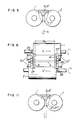
- the drums are movable in the axial direction in accordance with a change in the breadth of the sheet.
- both drums 1,1' are movable in the axial direction as indicated by arrows X and X' so as to vary the breadth of the casting region, thereby attaining the sheet breadth W coinciding with the desired breadth W0.
- the axial movement of the drums is caused by a conventional mechanism which is omitted from the drawings.
- side refractory parts 6,6' are fitted into the space between both drums 1,1'.
- springs 29,29' as pressing means are provided besides the aforementioned springs 9,9' so as to force each of the cooling plates 27,27' against the trunk surface of the drum 1,1', respectively.
- each of the cooling plates 27,27' has such a curved configuration as to fit the outer surface of the drum, and is forced by the spring 29 or 29' into contact with only one of the drums 1,1'. It will be understood that the described construction of the side dams and pressing springs enables the invention to be applied also to the continuous casting apparatus in which the drums are axially movable to vary the breadth of the sheet to be cast.
- each side dam is composed of two different portions: namely, a portion for maintaining the pool of the molten steel and a portion facing the region where the solidification shells are pressure-bonded.
- the side refractory parts for maintaining the pool of the molten steel is projected inwardly of the breadthwise ends of the sheet to be formed by an amount corresponding to the lateral spreading of the material which will be caused by the pressure-bonding of the solidified shells, above a position where the pressure-bonding of the solidification shells is commenced, thereby to delay the start of solidification of the breadthwise ends of the semi-solidified steel material.
- each side dam confronting the region where the pressure-bonding is effected i.e., the cooling plate of each side dam
- the cooling plate of each side dam is so positioned as to provide the desired sheet bredth after the pressure-bonding, by accomodating the possible lateral displacement of the material. Therefore, a breadthwise spreading force does not occur even when the steel material is spread laterally outwardly during the pressure-bonding of the solidification shells. It is thus possible to prevent any breakage or local wear of the side refractory parts.
- the leak of the molten steel is avoided even in the beginning period of the continuous casting in which the steel material in the pressure-bonded portion between two drums is still molten state, whereby the continuous casting is performed stably over the entire period.
- the lateral spreading of the steel material during the pressure-bonding of the solidification shells for ensuring the high quality of the core part of the cast product is allowed while ensuring the seal of the molten steel between the side dams and the end surfaces of the drums.
Applications Claiming Priority (2)
| Application Number | Priority Date | Filing Date | Title |
|---|---|---|---|
| JP171084/85 | 1985-08-05 | ||
| JP60171084A JPS6233047A (ja) | 1985-08-05 | 1985-08-05 | 双ドラム式連続鋳造機 |
Publications (3)
| Publication Number | Publication Date |
|---|---|
| EP0212423A2 true EP0212423A2 (fr) | 1987-03-04 |
| EP0212423A3 EP0212423A3 (en) | 1987-08-26 |
| EP0212423B1 EP0212423B1 (fr) | 1989-11-08 |
Family
ID=15916705
Family Applications (1)
| Application Number | Title | Priority Date | Filing Date |
|---|---|---|---|
| EP86110807A Expired EP0212423B1 (fr) | 1985-08-05 | 1986-08-05 | Appareil de coulée continue du type à tambour jumelé |
Country Status (5)
| Country | Link |
|---|---|
| US (1) | US4723590A (fr) |
| EP (1) | EP0212423B1 (fr) |
| JP (1) | JPS6233047A (fr) |
| KR (1) | KR900002120B1 (fr) |
| DE (1) | DE3666785D1 (fr) |
Cited By (7)
| Publication number | Priority date | Publication date | Assignee | Title |
|---|---|---|---|---|
| EP0285963A2 (fr) * | 1987-04-08 | 1988-10-12 | Nisshin Steel Co., Ltd. | Appareil de coulée continue pour bandes métalliques |
| FR2636259A1 (fr) * | 1988-09-14 | 1990-03-16 | Siderurgie Fse Inst Rech | Paroi laterale pour une installation de coulee continue entre parois mobiles et installation comportant cette paroi |
| EP0432073A1 (fr) * | 1989-12-07 | 1991-06-12 | USINOR SACILOR Société Anonyme | Installation de coulée continue de produits métalliques minces entre deux cylindres |
| FR2721843A1 (fr) * | 1994-06-30 | 1996-01-05 | Unisor Sacilor | Disposition de coulee continue entre cylindres a parois d'obturation laterale appliquees |
| EP0901851A1 (fr) * | 1997-09-12 | 1999-03-17 | Usinor | Face laterale pour l'obturation de l'espace de coulee d'une installation de coulee continue de bandes metalliques entre cylindres, et installation de coulee ainsi equipee |
| WO2010148454A1 (fr) * | 2009-06-24 | 2010-12-29 | Bluescope Steel Limited | Barrage latéral à usure ralentie avec insert |
| US7975756B2 (en) | 2006-03-24 | 2011-07-12 | Nucor Corporation | Long wear side dams |
Families Citing this family (15)
| Publication number | Priority date | Publication date | Assignee | Title |
|---|---|---|---|---|
| JPS6483337A (en) * | 1987-09-22 | 1989-03-29 | Ishikawajima Harima Heavy Ind | Twin roll type continuous casting machine |
| US5137075A (en) * | 1987-10-13 | 1992-08-11 | Ltv Steel Company, Inc. | Continuous casting apparatus and method |
| JPS63191213U (fr) * | 1988-05-27 | 1988-12-09 | ||
| GB8910906D0 (en) * | 1989-05-12 | 1989-06-28 | Davy Distington Ltd | Rotary strip caster edge containment |
| FR2647376B1 (fr) * | 1989-05-29 | 1991-09-13 | Siderurgie Fse Inst Rech | Dispositif de coulee continue de metal liquide entre deux cylindres |
| JPH03142045A (ja) * | 1989-10-27 | 1991-06-17 | Nisshin Steel Co Ltd | 金属薄板の連続鋳造方法および装置 |
| AUPP406798A0 (en) * | 1998-06-12 | 1998-07-02 | Bhp Steel (Jla) Pty Limited | Strip casting apparatus |
| US7503375B2 (en) * | 2006-05-19 | 2009-03-17 | Nucor Corporation | Method and apparatus for continuously casting thin strip |
| KR100841774B1 (ko) | 2006-12-26 | 2008-06-27 | 주식회사 포스코 | 쌍롤식 박판 주조기의 에지댐 제어 방법 |
| US7888158B1 (en) * | 2009-07-21 | 2011-02-15 | Sears Jr James B | System and method for making a photovoltaic unit |
| US20110036530A1 (en) * | 2009-08-11 | 2011-02-17 | Sears Jr James B | System and Method for Integrally Casting Multilayer Metallic Structures |
| US20110036531A1 (en) * | 2009-08-11 | 2011-02-17 | Sears Jr James B | System and Method for Integrally Casting Multilayer Metallic Structures |
| JP5837758B2 (ja) | 2011-04-27 | 2015-12-24 | キャストリップ・リミテッド・ライアビリティ・カンパニー | 双ロール鋳造装置及びその制御方法 |
| JP7233161B2 (ja) * | 2016-11-07 | 2023-03-06 | 日本製鉄株式会社 | サイドシール装置、双ロール式連続鋳造装置、及び、薄肉鋳片の製造方法 |
| WO2019239868A1 (fr) * | 2018-06-12 | 2019-12-19 | 日本製鉄株式会社 | Procédé pour la fabrication d'une brame coulée mince |
Citations (6)
| Publication number | Priority date | Publication date | Assignee | Title |
|---|---|---|---|---|
| JPS58187244A (ja) * | 1982-04-23 | 1983-11-01 | Hitachi Zosen Corp | 鋳片連続鋳造設備におけるシエル形成法 |
| JPS58218358A (ja) * | 1982-06-14 | 1983-12-19 | Nippon Kokan Kk <Nkk> | 鋼板の連続鋳造における鋳造開始法 |
| JPS59118249A (ja) * | 1982-12-22 | 1984-07-07 | Ishikawajima Harima Heavy Ind Co Ltd | 鋼板の連続鋳造方法 |
| EP0127319A1 (fr) * | 1983-04-28 | 1984-12-05 | Kawasaki Steel Corporation | Appareil de coulée continue pour la production de bandes coulées |
| JPS6021161A (ja) * | 1983-07-18 | 1985-02-02 | Mitsubishi Heavy Ind Ltd | 薄板連続鋳造装置 |
| JPS6033859A (ja) * | 1983-08-05 | 1985-02-21 | Mitsubishi Heavy Ind Ltd | 薄板連続鋳造装置 |
Family Cites Families (8)
| Publication number | Priority date | Publication date | Assignee | Title |
|---|---|---|---|---|
| JPS5577962A (en) * | 1978-12-11 | 1980-06-12 | Mitsubishi Heavy Ind Ltd | Continuous casting method of steel |
| JPS579565A (en) * | 1980-06-19 | 1982-01-19 | Mitsubishi Heavy Ind Ltd | Continuous casting equipment for metallic sheet |
| JPS579566A (en) * | 1980-06-23 | 1982-01-19 | Mitsubishi Heavy Ind Ltd | Direct rolling type continuous casting method of metallic sheet |
| JPS5794456A (en) * | 1980-12-03 | 1982-06-11 | Kawasaki Steel Corp | Continuous manufacture device for metallic thin plate |
| JPS5838640A (ja) * | 1981-08-31 | 1983-03-07 | Kawasaki Steel Corp | 薄板の連続鋳造装置 |
| JPS59175456U (ja) * | 1983-05-11 | 1984-11-22 | 石川島播磨重工業株式会社 | 連続鋳造設備 |
| JPS6030556A (ja) * | 1983-07-29 | 1985-02-16 | Nippon Kokan Kk <Nkk> | 金属板の連続鋳造装置 |
| JPS60130450A (ja) * | 1983-12-16 | 1985-07-11 | Mitsubishi Heavy Ind Ltd | 薄板連続鋳造装置 |
-
1985
- 1985-08-05 JP JP60171084A patent/JPS6233047A/ja active Granted
-
1986
- 1986-08-02 KR KR1019860006397A patent/KR900002120B1/ko not_active IP Right Cessation
- 1986-08-05 EP EP86110807A patent/EP0212423B1/fr not_active Expired
- 1986-08-05 US US06/893,173 patent/US4723590A/en not_active Expired - Lifetime
- 1986-08-05 DE DE8686110807T patent/DE3666785D1/de not_active Expired
Patent Citations (6)
| Publication number | Priority date | Publication date | Assignee | Title |
|---|---|---|---|---|
| JPS58187244A (ja) * | 1982-04-23 | 1983-11-01 | Hitachi Zosen Corp | 鋳片連続鋳造設備におけるシエル形成法 |
| JPS58218358A (ja) * | 1982-06-14 | 1983-12-19 | Nippon Kokan Kk <Nkk> | 鋼板の連続鋳造における鋳造開始法 |
| JPS59118249A (ja) * | 1982-12-22 | 1984-07-07 | Ishikawajima Harima Heavy Ind Co Ltd | 鋼板の連続鋳造方法 |
| EP0127319A1 (fr) * | 1983-04-28 | 1984-12-05 | Kawasaki Steel Corporation | Appareil de coulée continue pour la production de bandes coulées |
| JPS6021161A (ja) * | 1983-07-18 | 1985-02-02 | Mitsubishi Heavy Ind Ltd | 薄板連続鋳造装置 |
| JPS6033859A (ja) * | 1983-08-05 | 1985-02-21 | Mitsubishi Heavy Ind Ltd | 薄板連続鋳造装置 |
Non-Patent Citations (5)
| Title |
|---|
| PATENT ABSTRACTS OF JAPAN, vol. 8, no. 238 (M-335)[1675], 31st October 1984; & JP - A - 59 118 249 (ISHIKAWAJIMA HARIMA) 07-07-1984 * |
| PATENT ABSTRACTS OF JAPAN, vol. 8, no. 28 (M-274)[1465], 7th February 1984; & JP - A - 58 187 244 (HITACHI) 01-11-1983 * |
| PATENT ABSTRACTS OF JAPAN, vol. 8, no. 73 (M-287)[1510], 5th April 1984; & JP - A - 58 218 358 (NIPPON KOKAN) 19-12-1983 * |
| PATENT ABSTRACTS OF JAPAN, vol. 9, no. 142 (M-388)[1865], 18th June 1985; & JP - A - 60 021161 (MITSUBISHI JUKOGYO) 02-02-1985 * |
| PATENT ABSTRACTS OF JAPAN, vol. 9, no. 158 (M-393)[1881], 3rd July 1985; & JP - A - 60 033859 (MITSUBISHI JUKOGYO) 21-02-1985 * |
Cited By (17)
| Publication number | Priority date | Publication date | Assignee | Title |
|---|---|---|---|---|
| EP0285963A2 (fr) * | 1987-04-08 | 1988-10-12 | Nisshin Steel Co., Ltd. | Appareil de coulée continue pour bandes métalliques |
| EP0285963A3 (en) * | 1987-04-08 | 1989-04-26 | Nisshin Steel Co., Ltd. | Continuous casting apparatus for metal strip |
| FR2636259A1 (fr) * | 1988-09-14 | 1990-03-16 | Siderurgie Fse Inst Rech | Paroi laterale pour une installation de coulee continue entre parois mobiles et installation comportant cette paroi |
| EP0360635A1 (fr) * | 1988-09-14 | 1990-03-28 | Usinor Sacilor | Paroi latérale pour une installation de coulée continue entre parois mobiles, installation comportant cette paroi et procédé adapté de coulée continue de produits métalliques minces |
| AU618836B2 (en) * | 1988-09-14 | 1992-01-09 | Institut De Recherches De La Siderurgie Francaise (Irsid) | Lateral wall for an installation for continuous casting between movable walls, installation possessing this wall and suitable process for the continuous casting of thin metal products |
| EP0432073A1 (fr) * | 1989-12-07 | 1991-06-12 | USINOR SACILOR Société Anonyme | Installation de coulée continue de produits métalliques minces entre deux cylindres |
| FR2655577A1 (fr) * | 1989-12-07 | 1991-06-14 | Siderurgie Fse Inst Rech | Installation de coulee continue de produits metalliques minces entre deux cylindres. |
| US5058658A (en) * | 1989-12-07 | 1991-10-22 | Usinor Sacilor | Installation for the continuous casting of thin metal products between two rolls |
| FR2721843A1 (fr) * | 1994-06-30 | 1996-01-05 | Unisor Sacilor | Disposition de coulee continue entre cylindres a parois d'obturation laterale appliquees |
| EP0698433A1 (fr) * | 1994-06-30 | 1996-02-28 | USINOR SACILOR Société Anonyme | Dispositif de coulée continue entre cylindres à parois d'obturation latérale appliquées |
| US5584335A (en) * | 1994-06-30 | 1996-12-17 | Usinor-Sacilor | Device for continuous casting between rolls with applied side dams |
| USRE37214E1 (en) | 1994-06-30 | 2001-06-12 | Usinor | Device for continuous casting between rolls with applied side dams |
| EP0901851A1 (fr) * | 1997-09-12 | 1999-03-17 | Usinor | Face laterale pour l'obturation de l'espace de coulee d'une installation de coulee continue de bandes metalliques entre cylindres, et installation de coulee ainsi equipee |
| FR2768354A1 (fr) * | 1997-09-12 | 1999-03-19 | Usinor | Face laterale pour l'obturation de l'espace de coulee d'une installation de coulee continue de bandes metalliques entre cylindres, et installation de coulee ainsi equipee |
| CN1074328C (zh) * | 1997-09-12 | 2001-11-07 | 于西纳公司 | 封闭金属带材双辊连铸机铸腔的侧壁和配有该侧壁的连铸机 |
| US7975756B2 (en) | 2006-03-24 | 2011-07-12 | Nucor Corporation | Long wear side dams |
| WO2010148454A1 (fr) * | 2009-06-24 | 2010-12-29 | Bluescope Steel Limited | Barrage latéral à usure ralentie avec insert |
Also Published As
| Publication number | Publication date |
|---|---|
| KR900002120B1 (ko) | 1990-04-02 |
| DE3666785D1 (en) | 1989-12-14 |
| KR870001885A (ko) | 1987-03-28 |
| US4723590A (en) | 1988-02-09 |
| EP0212423A3 (en) | 1987-08-26 |
| JPH0433536B2 (fr) | 1992-06-03 |
| EP0212423B1 (fr) | 1989-11-08 |
| JPS6233047A (ja) | 1987-02-13 |
Similar Documents
| Publication | Publication Date | Title |
|---|---|---|
| EP0212423A2 (fr) | Appareil de coulée continue du type à tambour jumelé | |
| US4809768A (en) | Cooling rolls for producing rapidly solidified metal strip sheets | |
| EP0390924B1 (fr) | Installation de coulee en continu de minces plaques metalliques | |
| EP0388472B1 (fr) | Appareil de coulee en continu de minces toles metalliques | |
| EP0782894B2 (fr) | Dispositif de coulée continue entre cylindres | |
| JP2949122B2 (ja) | ロール間で連続鋳造を行う装置 | |
| WO2019092903A1 (fr) | Dispositif d'étanchéité latéral, dispositif de coulée continue de type à double rouleau et procédé destiné à la fabrication d'une brame mince | |
| EP0448773A2 (fr) | Moule de coulée continue et procédé de coulée continue | |
| EP0265164B1 (fr) | Procédé et dispositif de préparation de bandes métalliques solidifiées rapidement | |
| US5154222A (en) | Device for the continuous casting of thin metal products between two cooled rotating rolls | |
| TW504414B (en) | Side wall for closing off the casting space of a plant for the twin-roll continuous casting of metal strip, and casting plant thus equipped | |
| JP3217638B2 (ja) | 連続鋳造方法及びベルト式連続鋳造方法 | |
| JPS632536A (ja) | 幅可変鋳型 | |
| JPH0749138B2 (ja) | 薄板連続鋳造装置 | |
| JPH01317657A (ja) | 急冷金属薄帯の製造装置 | |
| JPH0362504B2 (fr) | ||
| AU6492690A (en) | Process and device for the continuous casting of thin metal products between two rolls | |
| AU703994B2 (en) | Twin roll continuous caster | |
| DR Thornton BSc | Moulds for Continuous Casting | |
| JPS6072651A (ja) | 銅の連続鋳造装置 | |
| JP2000015399A (ja) | 鋳型用耐火リングとこれを用いた垂直連続鋳造用鋳型 | |
| JPS63252649A (ja) | 薄鋳片連続鋳造機 | |
| JPS6326244A (ja) | 薄鋳片連続鋳造用固定短辺 | |
| JPH05318041A (ja) | 双ドラム式薄板連続鋳造装置 | |
| JPS58188549A (ja) | 鋼板の連続鋳造装置 |
Legal Events
| Date | Code | Title | Description |
|---|---|---|---|
| PUAI | Public reference made under article 153(3) epc to a published international application that has entered the european phase |
Free format text: ORIGINAL CODE: 0009012 |
|
| AK | Designated contracting states |
Kind code of ref document: A2 Designated state(s): DE FR GB IT |
|
| PUAL | Search report despatched |
Free format text: ORIGINAL CODE: 0009013 |
|
| AK | Designated contracting states |
Kind code of ref document: A3 Designated state(s): DE FR GB IT |
|
| 17P | Request for examination filed |
Effective date: 19870827 |
|
| 17Q | First examination report despatched |
Effective date: 19880315 |
|
| GRAA | (expected) grant |
Free format text: ORIGINAL CODE: 0009210 |
|
| AK | Designated contracting states |
Kind code of ref document: B1 Designated state(s): DE FR GB IT |
|
| REF | Corresponds to: |
Ref document number: 3666785 Country of ref document: DE Date of ref document: 19891214 |
|
| ITF | It: translation for a ep patent filed |
Owner name: MODIANO & ASSOCIATI S.R.L. |
|
| ET | Fr: translation filed | ||
| PLBE | No opposition filed within time limit |
Free format text: ORIGINAL CODE: 0009261 |
|
| STAA | Information on the status of an ep patent application or granted ep patent |
Free format text: STATUS: NO OPPOSITION FILED WITHIN TIME LIMIT |
|
| 26N | No opposition filed | ||
| ITTA | It: last paid annual fee | ||
| REG | Reference to a national code |
Ref country code: GB Ref legal event code: IF02 |
|
| PGFP | Annual fee paid to national office [announced via postgrant information from national office to epo] |
Ref country code: FR Payment date: 20020618 Year of fee payment: 17 |
|
| PGFP | Annual fee paid to national office [announced via postgrant information from national office to epo] |
Ref country code: GB Payment date: 20020725 Year of fee payment: 17 |
|
| PGFP | Annual fee paid to national office [announced via postgrant information from national office to epo] |
Ref country code: DE Payment date: 20021030 Year of fee payment: 17 |
|
| PG25 | Lapsed in a contracting state [announced via postgrant information from national office to epo] |
Ref country code: GB Free format text: LAPSE BECAUSE OF NON-PAYMENT OF DUE FEES Effective date: 20030805 |
|
| PG25 | Lapsed in a contracting state [announced via postgrant information from national office to epo] |
Ref country code: DE Free format text: LAPSE BECAUSE OF NON-PAYMENT OF DUE FEES Effective date: 20040302 |
|
| GBPC | Gb: european patent ceased through non-payment of renewal fee |
Effective date: 20030805 |
|
| PG25 | Lapsed in a contracting state [announced via postgrant information from national office to epo] |
Ref country code: FR Free format text: LAPSE BECAUSE OF NON-PAYMENT OF DUE FEES Effective date: 20040430 |
|
| REG | Reference to a national code |
Ref country code: FR Ref legal event code: ST |
|
| PG25 | Lapsed in a contracting state [announced via postgrant information from national office to epo] |
Ref country code: IT Free format text: LAPSE BECAUSE OF NON-PAYMENT OF DUE FEES Effective date: 20050805 |