EP0205379B1 - Schloss, insbesondere für Sicherheitsgurte - Google Patents
Schloss, insbesondere für Sicherheitsgurte Download PDFInfo
- Publication number
- EP0205379B1 EP0205379B1 EP86401175A EP86401175A EP0205379B1 EP 0205379 B1 EP0205379 B1 EP 0205379B1 EP 86401175 A EP86401175 A EP 86401175A EP 86401175 A EP86401175 A EP 86401175A EP 0205379 B1 EP0205379 B1 EP 0205379B1
- Authority
- EP
- European Patent Office
- Prior art keywords
- locking member
- latch
- buckle
- buckle according
- projection
- Prior art date
- Legal status (The legal status is an assumption and is not a legal conclusion. Google has not performed a legal analysis and makes no representation as to the accuracy of the status listed.)
- Expired
Links
- 238000006073 displacement reaction Methods 0.000 claims description 2
- 230000000284 resting effect Effects 0.000 claims description 2
- 230000007935 neutral effect Effects 0.000 description 6
- 239000002184 metal Substances 0.000 description 4
- 238000010276 construction Methods 0.000 description 3
- 238000004519 manufacturing process Methods 0.000 description 3
- 230000014759 maintenance of location Effects 0.000 description 2
- 238000010008 shearing Methods 0.000 description 2
- 208000031968 Cadaver Diseases 0.000 description 1
- 230000000694 effects Effects 0.000 description 1
- 230000005489 elastic deformation Effects 0.000 description 1
- 238000005516 engineering process Methods 0.000 description 1
- 239000000463 material Substances 0.000 description 1
- 230000010355 oscillation Effects 0.000 description 1
- 230000000717 retained effect Effects 0.000 description 1
Images
Classifications
-
- A—HUMAN NECESSITIES
- A44—HABERDASHERY; JEWELLERY
- A44B—BUTTONS, PINS, BUCKLES, SLIDE FASTENERS, OR THE LIKE
- A44B11/00—Buckles; Similar fasteners for interconnecting straps or the like, e.g. for safety belts
- A44B11/25—Buckles; Similar fasteners for interconnecting straps or the like, e.g. for safety belts with two or more separable parts
- A44B11/2503—Safety buckles
- A44B11/2507—Safety buckles actuated by a push-button
- A44B11/2523—Safety buckles actuated by a push-button acting parallel to the main plane of the buckle and in the same direction as the fastening action
-
- Y—GENERAL TAGGING OF NEW TECHNOLOGICAL DEVELOPMENTS; GENERAL TAGGING OF CROSS-SECTIONAL TECHNOLOGIES SPANNING OVER SEVERAL SECTIONS OF THE IPC; TECHNICAL SUBJECTS COVERED BY FORMER USPC CROSS-REFERENCE ART COLLECTIONS [XRACs] AND DIGESTS
- Y10—TECHNICAL SUBJECTS COVERED BY FORMER USPC
- Y10T—TECHNICAL SUBJECTS COVERED BY FORMER US CLASSIFICATION
- Y10T24/00—Buckles, buttons, clasps, etc.
- Y10T24/45—Separable-fastener or required component thereof [e.g., projection and cavity to complete interlock]
- Y10T24/45225—Separable-fastener or required component thereof [e.g., projection and cavity to complete interlock] including member having distinct formations and mating member selectively interlocking therewith
- Y10T24/45602—Receiving member includes either movable connection between interlocking components or variable configuration cavity
- Y10T24/45623—Receiving member includes either movable connection between interlocking components or variable configuration cavity and operator therefor
- Y10T24/45639—Receiving member includes either movable connection between interlocking components or variable configuration cavity and operator therefor including pivotally connected element on receiving member
- Y10T24/45654—Receiving member includes either movable connection between interlocking components or variable configuration cavity and operator therefor including pivotally connected element on receiving member for shifting slidably connected and guided, nonself-biasing interlocking component
-
- Y—GENERAL TAGGING OF NEW TECHNOLOGICAL DEVELOPMENTS; GENERAL TAGGING OF CROSS-SECTIONAL TECHNOLOGIES SPANNING OVER SEVERAL SECTIONS OF THE IPC; TECHNICAL SUBJECTS COVERED BY FORMER USPC CROSS-REFERENCE ART COLLECTIONS [XRACs] AND DIGESTS
- Y10—TECHNICAL SUBJECTS COVERED BY FORMER USPC
- Y10T—TECHNICAL SUBJECTS COVERED BY FORMER US CLASSIFICATION
- Y10T24/00—Buckles, buttons, clasps, etc.
- Y10T24/45—Separable-fastener or required component thereof [e.g., projection and cavity to complete interlock]
- Y10T24/45225—Separable-fastener or required component thereof [e.g., projection and cavity to complete interlock] including member having distinct formations and mating member selectively interlocking therewith
- Y10T24/45602—Receiving member includes either movable connection between interlocking components or variable configuration cavity
- Y10T24/45623—Receiving member includes either movable connection between interlocking components or variable configuration cavity and operator therefor
- Y10T24/4566—Receiving member includes either movable connection between interlocking components or variable configuration cavity and operator therefor including slidably connected and guided element on receiving member
- Y10T24/45665—Receiving member includes either movable connection between interlocking components or variable configuration cavity and operator therefor including slidably connected and guided element on receiving member for shifting pivotally connected interlocking component
-
- Y—GENERAL TAGGING OF NEW TECHNOLOGICAL DEVELOPMENTS; GENERAL TAGGING OF CROSS-SECTIONAL TECHNOLOGIES SPANNING OVER SEVERAL SECTIONS OF THE IPC; TECHNICAL SUBJECTS COVERED BY FORMER USPC CROSS-REFERENCE ART COLLECTIONS [XRACs] AND DIGESTS
- Y10—TECHNICAL SUBJECTS COVERED BY FORMER USPC
- Y10T—TECHNICAL SUBJECTS COVERED BY FORMER US CLASSIFICATION
- Y10T24/00—Buckles, buttons, clasps, etc.
- Y10T24/45—Separable-fastener or required component thereof [e.g., projection and cavity to complete interlock]
- Y10T24/45225—Separable-fastener or required component thereof [e.g., projection and cavity to complete interlock] including member having distinct formations and mating member selectively interlocking therewith
- Y10T24/45602—Receiving member includes either movable connection between interlocking components or variable configuration cavity
- Y10T24/45675—Receiving member includes either movable connection between interlocking components or variable configuration cavity having pivotally connected interlocking component
Definitions
- the present invention relates to devices intended to retain a passenger in a motor vehicle in his seat in the event of sudden deceleration thereof, for example during emergency braking or a collision.
- the invention relates to a loop which, in a device of the type indicated. is intended to removably fix a strand of a safety strap to a fixed point on the vehicle body, for example by means of a tab forming a bolt bolt.
- loops comprising a housing in which is placed a bracket in the form of a stirrup which is intended to be fixed to a retaining means fixed relative to the body of the vehicle and which defines between its wings , a guide corridor for the bolt opening at one end of this stirrup.
- These loops further comprise a locking member mounted oscillating in the stirrup around an axis which is perpendicular to the wings of this stirrup as well as a stop member mounted sliding in these wings and erasable by means of a button. control, against the action of an elastic return device.
- the bolt is retained in the loop by a projecting part of the locking member which prevents the withdrawal of the bolt from the locking passage, for example by entering an opening in the bolt.
- this projecting part comes to cooperate with a stop edge formed in the bottom of the support stirrup, possibly by elastic deformation of the axis of oscillation of the locking member in the stirrup, which makes it possible to obtain a high efficiency of the buckle and a considerable retaining force of the bolt.
- Document FR-2482430 also discloses a seat belt buckle comprising a support intended to be fixed to a retaining means and defining a rectilinear passage into which the bolt can be introduced and which defines a sliding point for that -this.
- the bolt locking member is articulated on the support around an axis which extends parallel to the plane of the passage.
- This locking member may have a first abutment surface retaining the bolt and extending perpendicular to the plane of the passage, being transverse with respect thereto, in the locked position of the loop while the locking member may also have at least a second abutment surface which is intended, in the locked position of the loop, to come into contact with a stop member mounted movable in translation on the support in a direction perpendicular to the axis of articulation of the locking member. The movement of this stop member releases the locking member and therefore the pin when opening the loop which is controlled by an operating button mounted on the support so as to be able to move in the same direction as the stop device.
- the stop member is formed by a one-piece body having means for guiding and holding the springs. 'extending on either side of this body in opposite directions perpendicular to the axis of articulation of the locking member.
- the object of the invention is therefore to provide a seat belt buckle whose construction is simple and easy assembly, by reducing the number of members involved in the constitution of such a buckle.
- Another object of the invention is to provide a seat belt buckle which is smaller and lighter than the buckles of the prior art and the manufacture of which can be undertaken without respecting tight tolerances.
- the subject of the invention is a buckle, in particular a seat belt for a motor vehicle, intended to removably fix a strand thereof to a fixed point on the vehicle body, by means of a bolt forming bolt secured to the strand to be fixed, said loop comprising a housing in which is placed a body intended to be fixed to a retaining means secured to the vehicle and which defines a rectilinear passage into which the bolt and, in addition, a member locking device for holding the bolt in the locked position and a bolt unlocking control member, characterized in that the locking member is mounted oscillating and slidingly movable in said body between a locking position of said bolt and a position of release of the latter and in that it comprises at its ends means intended to cooperate with stop surfaces of the body and the bolt under the action of a crossing device from neutral.
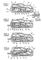
- a seat belt buckle according to the invention comprises a housing 1 consisting, in a manner known per se, of an upper element 2 and of a lower element 3. Inside this housing 1 is disposed a body 4 which is, in longitudinal section, in the general form of an elongated C. A locking member 5, which will be described in more detail below, is housed inside this body 4. An unlocking control member 6, having one end in the form of a ramp 7, is slidingly disposed between the body 4 and the upper element 2 of the housing 1.
- the housing 1 includes a first lumen 8 into which opens one end of the unlocking control member 6 so that the user of the seat belt buckle has access to this member 6.
- the housing 1 also includes a first opening 9, the walls of which are inclined, opening into an orifice 10 formed in the body 4. As we will see later, this opening 9 and this orifice 10 define a passage for for example a tongue forming bolt secured to a strand to be attached to the seat belt.
- the housing 1 also includes a second opening 11 formed in the end of the housing 1 opposite the end in which the opening 9 is made.
- This opening 11 is formed opposite the ends of two walls constituting the body 4.
- This opening 11 is intended to allow the passage of a retaining means (not shown), one end of which is fixed to the vehicle and the other end of which is fixed to the body 4 so as to make the body 4 integral with the vehicle.
- the ends of the two walls constituting a body 4a can protrude outside a housing 1a, through an opening 11a formed in the end of the housing 1a opposite the end in which an opening is made allowing the introduction bolt in the loop.
- the locking member 5 has a first projection 12 which, in the position shown in FIG. 1, extends through a lumen 13 formed in the upper wall of the body 4 opposite the unlocking control member 6. In this position, the first projection 12 is therefore disposed above the passage defined by the opening 9 of the housing 1 and the orifice 10 of the body 4.
- This locking member comprises, at its other end, a second projection 14 which, in the position shown in this figure, bears against an edge of the upper wall of the body 4.
- This end of the locking member 5 also includes a centering pin 15 on which is disposed one end of a device for crossing neutral point which can be constituted for example by a spring 16, the other end of which takes bearing on a concrete 17 formed in the lower wall of the body 4, and which is inclined towards the inside thereof, relative to the direction of movement of the locking member inside the body 4, as is will see it later.
- a device for crossing neutral point which can be constituted for example by a spring 16, the other end of which takes bearing on a concrete 17 formed in the lower wall of the body 4, and which is inclined towards the inside thereof, relative to the direction of movement of the locking member inside the body 4, as is will see it later.
- This spring 16 exerts a force which tends to hold the second projection 14 of the locking member 5 against the upper wall of the body 4 and to push this member 5 so that the first projection 12 thereof comes to bear against a flange light 13.
- the locking member 5 comprises two wings formed by stamping and integrally formed with the rest of the locking member, of which only one, 18, is shown and in which is disposed an axis 19 which, as we will see it later, may be an axis added in the wings of the locking member 5 or an axis coming integrally with them.
- the locking member 5 is mounted oscillating around this axis 19 and movable by sliding in the body 4.
- the projection 14 thereof will be located opposite a lumen 23 formed in the upper wall of the body 4 and defining an edge thereof.
- the spring 16 and possibly a flange 24 of the body 4 formed substantially opposite the wings of the member locking 5, will then cause the locking member to move angularly about its axis 19 resting on the lower wall of the body 4.
- the projection 12 of the locking member enters the lumen 20 of the body 4 under the action of the spring 16.
- the projection 14 of the locking member 5 extends beyond the upper wall of the body 4 and when the user releases his pressure on the bolt 21, the locking member 5 is brought back under the effect of the action of the spring 16, in a stable position in which the projection 12 extends through the recess 22 of the bolt 21 and is in abutment against a light stop edge 20 of the body 4, thus ensuring locking the bolt in the loop.
- the movement of the locking member inside the body 4 is limited on the one hand by the support of the projection 12 on the light stop edge 20 and on the other hand by the projection 14 coming in support against a wall of the light 23.
- unlocking control member 6 is provided with a return spring (not shown) which tends to return it to the rest position as shown in FIG. 1.
- the projection 12 ensuring the retention of the bolt inside the loop is subjected to a shearing force when a traction is exerted on the bolt 21.
- This projection 12 must therefore be sufficient to withstand significant forces as is the rule. in the matter. Also, different possibilities of manufacturing the locking member can be envisaged.
- a locking member 5a can be made of pressed sheet metal of small thickness in which an axis 19a is attached.
- one of the ends of this member has a projection 12a ensuring the locking of the bolt, which is doubled so as to have sufficient resistance to shearing.
- Wings 18a of the locking member have two recesses in which the axis 19a is arranged. This axis 19a can be force-fitted into the recesses of the wings 18a so that it is integral with the rest of the locking member or it can be free to rotate in these recesses if it is guided laterally in the body 4.
- the locking member can be in the form of a deep-drawn piece 30 made of thick sheet metal, a projection 31 ensuring the retention of the bolt in the seat belt buckle is not doubled.
- a projection 32, a lumen 33 and a stud 34 have shapes similar to the projections 14 and 14a, the lumen 25 and the studs 15 and 15a respectively of the previous embodiments.
- This locking member 30 also includes wings 35 which are made of thicker sheet metal than previously. It is therefore possible to produce, from material with these wings 35, projecting parts 36 fulfilling the same role as the ends of the axes 19 and 19a, that is to say coming to bear on the lower wall of the body 4 so as to allow tilting and sliding movement of the locking member 30 in this body 4.
- the projecting parts 36 may advantageously be of polygonal section.
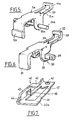
- FIG. 7 an embodiment of a body 40 forming part of a seat belt buckle according to the invention.
- This body 40 is in the form of a stirrup stamped in a metal plate having a bottom wall 40a in which are formed a light 41, similar to the light 20 shown in FIGS. 1 and 4, and a recess 42 by means of which the body 40 is fixed to a retaining means secured to the vehicle.
- This body 40 also comprises two side walls of which only one, 43, is shown and in which is formed by stamping a flange 44 defining a passage for the bolt.
- a tongue 45 extends substantially perpendicular to the side wall 43, so as to constitute an upper wall of the body whose edges fulfill the same role as the lights 13 and 23 shown in FIGS. 1 and 4.
- the side wall 43 is also produced by stamping a flange 46 projecting towards the inside of the body and intended to constitute a stop for the wings of the locking member so as to limit its movement of movement forwards under the action of the spring 16.
- the body 40 does not have a bearing surface for the projection ensuring the locking of the bolt, when the latter is in the unlocked position and it is therefore necessary to provide means for limiting its moving forward.
- a stud 47 intended to receive one end of the device passing through neutral, extends into the lumen 41.
- This stud 47 is also inclined towards the inside of the body 40 relative to the direction of movement of the locking member in said body.
Landscapes
- Automotive Seat Belt Assembly (AREA)
- Buckles (AREA)
Claims (10)
Applications Claiming Priority (2)
| Application Number | Priority Date | Filing Date | Title |
|---|---|---|---|
| FR8508755A FR2582916B1 (fr) | 1985-06-10 | 1985-06-10 | Boucle, notamment de ceinture de securite. |
| FR8508755 | 1985-06-10 |
Publications (2)
| Publication Number | Publication Date |
|---|---|
| EP0205379A1 EP0205379A1 (de) | 1986-12-17 |
| EP0205379B1 true EP0205379B1 (de) | 1988-09-28 |
Family
ID=9320065
Family Applications (1)
| Application Number | Title | Priority Date | Filing Date |
|---|---|---|---|
| EP86401175A Expired EP0205379B1 (de) | 1985-06-10 | 1986-06-03 | Schloss, insbesondere für Sicherheitsgurte |
Country Status (6)
| Country | Link |
|---|---|
| US (1) | US4677716A (de) |
| EP (1) | EP0205379B1 (de) |
| JP (1) | JPH0669404B2 (de) |
| DE (1) | DE3660789D1 (de) |
| ES (1) | ES294811Y (de) |
| FR (1) | FR2582916B1 (de) |
Cited By (1)
| Publication number | Priority date | Publication date | Assignee | Title |
|---|---|---|---|---|
| DE4123280C2 (de) * | 1990-07-13 | 2000-02-24 | Autoflug Gmbh | Gurtverschluß für einen Sicherheitsgurt eines Kraftfahrzeuges |
Families Citing this family (14)
| Publication number | Priority date | Publication date | Assignee | Title |
|---|---|---|---|---|
| DE3731521A1 (de) * | 1987-09-18 | 1989-03-30 | Bsrd Ltd | Gurtschloss fuer einen sicherheitsgurt eines fahrzeugs, insbesondere kraftfahrzeugs |
| DE3832935C2 (de) * | 1987-10-05 | 1995-10-19 | Autoflug Gmbh | Verschluß für Sicherheitsgurte |
| US4942649A (en) * | 1988-02-25 | 1990-07-24 | Indiana Mills & Manufacturing, Inc. | Safety belt buckle |
| US4876772A (en) * | 1988-02-25 | 1989-10-31 | Indiana Mills & Manufacturing, Inc. | Safety belt buckle |
| GB2218457B (en) * | 1988-05-11 | 1992-03-18 | Gen Motors Corp | Seat belt buckle. |
| US4955115A (en) * | 1988-07-11 | 1990-09-11 | Kabushiki Kaisha Tokai-Rika-Denki-Seisakusho | Buckle device |
| JPH088644Y2 (ja) * | 1989-08-29 | 1996-03-13 | 株式会社東海理化電機製作所 | バックル装置 |
| GB2290104B (en) * | 1994-06-09 | 1997-09-17 | Michael Sacks | A connector |
| DE29810954U1 (de) * | 1998-06-18 | 1999-03-25 | TRW Occupant Restraint Systems GmbH & Co. KG, 73553 Alfdorf | Gurtschloß |
| JP2007111178A (ja) * | 2005-10-19 | 2007-05-10 | Tokai Rika Co Ltd | バックル装置 |
| GB2455058B (en) * | 2007-10-09 | 2012-05-30 | Motorola Mobility Inc | A cellular communication system and a method of operation therefor |
| CN108725376A (zh) * | 2018-06-15 | 2018-11-02 | 广西亿程科技有限公司 | 一种双侧受力保护的安全带 |
| US12220024B2 (en) * | 2022-05-26 | 2025-02-11 | Illinois Tool Works Inc. | Buckle |
| WO2023245556A1 (zh) * | 2022-06-23 | 2023-12-28 | 浙江吉利控股集团有限公司 | 锁扣和车辆 |
Family Cites Families (14)
| Publication number | Priority date | Publication date | Assignee | Title |
|---|---|---|---|---|
| DE452367C (de) * | 1927-11-12 | Siemens Schuckertwerke G M B H | Gegenstromschaltung fuer elektromagnetische Wendegetriebe | |
| US2893088A (en) * | 1956-04-27 | 1959-07-07 | Automotive Safety Associates | Safety belt buckle |
| FR2178731B1 (de) * | 1961-10-04 | 1975-03-21 | Ferodo Sa | |
| CH452367A (de) * | 1967-09-20 | 1968-05-31 | Waibel Hans | Schloss für Sicherheitsgurte |
| JPS5411617Y2 (de) * | 1974-06-21 | 1979-05-24 | ||
| JPS5519122Y2 (de) * | 1975-08-19 | 1980-05-07 | ||
| FR2326209A1 (fr) * | 1975-10-03 | 1977-04-29 | Bayon Patrice | Serrure pour ceinture de securite et objets analogues |
| DE2740458C3 (de) * | 1977-09-08 | 1983-12-29 | Carl Stahl Gmbh & Co Kg, Gurt- Und Bandweberei, 7922 Herbrechtingen | Gurtschloß, insbesondere für Sicherheitsgurte |
| DE2828082A1 (de) * | 1978-06-27 | 1980-01-10 | Stahl Gurt Bandweberei | Gurtschloss, insbesondere fuer sicherheitsgurte |
| SE426018B (sv) * | 1980-03-12 | 1982-12-06 | Safety Transport Int Dev | Spenne for sekerhetsbelte |
| FR2482429A2 (fr) * | 1980-05-14 | 1981-11-20 | Peugeot Aciers Et Outillage | Boucle pour sangle de securite |
| FR2482430B1 (de) * | 1980-05-14 | 1983-12-23 | Peugeot Aciers Et Outillage | |
| FR2509969A1 (fr) * | 1981-07-27 | 1983-01-28 | Klippan Nv | Boucle de fermeture de ceinture de securite a loquet pivotant |
| SE451231B (sv) * | 1982-12-23 | 1987-09-21 | Autoliv Dev | Lasanordning for sekerhetsselar i fordon |
-
1985
- 1985-06-10 FR FR8508755A patent/FR2582916B1/fr not_active Expired
-
1986
- 1986-06-02 US US06/869,787 patent/US4677716A/en not_active Expired - Lifetime
- 1986-06-02 ES ES1986294811U patent/ES294811Y/es not_active Expired
- 1986-06-03 EP EP86401175A patent/EP0205379B1/de not_active Expired
- 1986-06-03 DE DE8686401175T patent/DE3660789D1/de not_active Expired
- 1986-06-10 JP JP61134737A patent/JPH0669404B2/ja not_active Expired - Lifetime
Cited By (1)
| Publication number | Priority date | Publication date | Assignee | Title |
|---|---|---|---|---|
| DE4123280C2 (de) * | 1990-07-13 | 2000-02-24 | Autoflug Gmbh | Gurtverschluß für einen Sicherheitsgurt eines Kraftfahrzeuges |
Also Published As
| Publication number | Publication date |
|---|---|
| ES294811U (es) | 1986-10-16 |
| JPS61284202A (ja) | 1986-12-15 |
| ES294811Y (es) | 1987-07-01 |
| EP0205379A1 (de) | 1986-12-17 |
| US4677716A (en) | 1987-07-07 |
| FR2582916A1 (fr) | 1986-12-12 |
| DE3660789D1 (en) | 1988-11-03 |
| FR2582916B1 (fr) | 1987-09-18 |
| JPH0669404B2 (ja) | 1994-09-07 |
Similar Documents
| Publication | Publication Date | Title |
|---|---|---|
| EP0205379B1 (de) | Schloss, insbesondere für Sicherheitsgurte | |
| EP0040143A1 (de) | Verschlussschnalle für Sicherheitsgurte | |
| EP0688695A1 (de) | Verriegelung eines beweglichen Bauteiles in einem Kraftfahrzeugsitz | |
| FR2552641A1 (fr) | Boucle de ceinture de securite d'un moyen de transport | |
| FR2477849A1 (fr) | Boucle de ceinture de securite | |
| FR2477991A1 (fr) | Dispositif de fixation d'une ferrure reglable dans differentes positions, en particulier d'une ferrure pour sieges de vehicule | |
| EP0040132A1 (de) | Verschlussschnalle für Sicherheitsgurte | |
| EP0016169B1 (de) | Schnalle für sicherheitsgürtel für fahrzeuge | |
| EP0211718B1 (de) | Schloss, insbesondere für Sicherheitsgurte in Kraftfahrzeugen | |
| EP0211717B1 (de) | Schloss, insbesondere für Sicherheitsgurte | |
| FR2550146A1 (fr) | Ferrure reglable pour ceinture de securite pour vehicules automobiles | |
| FR2671587A1 (fr) | Mecanisme de verrouillage d'une tige crantee. | |
| FR2518194A1 (fr) | Dispositif de fixation d'un objet en un point quelconque d'une regle profilee | |
| FR2852996A1 (fr) | Dispositif de verrouillage a deux poussees de commande | |
| EP0040574A1 (de) | Betätigungsvorrichtung für die Handbremse | |
| EP0225248B1 (de) | Schloss für Sicherheitsgurte, insbesondere in Kraftfahrzeugen | |
| FR2788549A1 (fr) | Verrou pour l'equipement automobile tel que verrou de porte, de coffre ou de dossier de siege rabattable | |
| EP0142428A1 (de) | Neigungsvorrichtung für Sitze, insbesondere für Kraftwagensitze | |
| EP0218517B1 (de) | Schloss, insbesondere für Sicherheitsgurte in Kraftfahrzeugen | |
| WO1983003741A1 (fr) | Boucle de ceinture de securite a loquet de blocage pivotant | |
| EP0079835B1 (de) | Sicherheitsgurtschnalle, insbesondere für Kraftfahrzeuge | |
| FR2553247A3 (fr) | Telephone, en particulier telephone pour automobile, equipe d'un dispositif de verrouillage perfectionne | |
| FR2703960A1 (fr) | Système de sécurité pour enfant. | |
| EP3210822A1 (de) | Vorrichtung zum einhaken eines fahrzeugsitzes ohne drehmoment in der halterung im falle einer kollision | |
| FR2553637A1 (fr) | Boucle de ceinture de securite |
Legal Events
| Date | Code | Title | Description |
|---|---|---|---|
| PUAI | Public reference made under article 153(3) epc to a published international application that has entered the european phase |
Free format text: ORIGINAL CODE: 0009012 |
|
| 17P | Request for examination filed |
Effective date: 19861017 |
|
| AK | Designated contracting states |
Kind code of ref document: A1 Designated state(s): DE GB IT SE |
|
| 17Q | First examination report despatched |
Effective date: 19880303 |
|
| GRAA | (expected) grant |
Free format text: ORIGINAL CODE: 0009210 |
|
| RAP1 | Party data changed (applicant data changed or rights of an application transferred) |
Owner name: ECIA - EQUIPEMENTS ET COMPOSANTS POUR L'INDUSTRIE |
|
| ITF | It: translation for a ep patent filed | ||
| AK | Designated contracting states |
Kind code of ref document: B1 Designated state(s): DE GB IT SE |
|
| GBT | Gb: translation of ep patent filed (gb section 77(6)(a)/1977) | ||
| REF | Corresponds to: |
Ref document number: 3660789 Country of ref document: DE Date of ref document: 19881103 |
|
| PLBE | No opposition filed within time limit |
Free format text: ORIGINAL CODE: 0009261 |
|
| STAA | Information on the status of an ep patent application or granted ep patent |
Free format text: STATUS: NO OPPOSITION FILED WITHIN TIME LIMIT |
|
| 26N | No opposition filed | ||
| ITTA | It: last paid annual fee | ||
| EAL | Se: european patent in force in sweden |
Ref document number: 86401175.4 |
|
| PGFP | Annual fee paid to national office [announced via postgrant information from national office to epo] |
Ref country code: SE Payment date: 19970627 Year of fee payment: 12 |
|
| PG25 | Lapsed in a contracting state [announced via postgrant information from national office to epo] |
Ref country code: SE Free format text: LAPSE BECAUSE OF NON-PAYMENT OF DUE FEES Effective date: 19980604 |
|
| EUG | Se: european patent has lapsed |
Ref document number: 86401175.4 |
|
| PGFP | Annual fee paid to national office [announced via postgrant information from national office to epo] |
Ref country code: GB Payment date: 20010619 Year of fee payment: 16 |
|
| PGFP | Annual fee paid to national office [announced via postgrant information from national office to epo] |
Ref country code: DE Payment date: 20010620 Year of fee payment: 16 |
|
| REG | Reference to a national code |
Ref country code: GB Ref legal event code: IF02 |
|
| PG25 | Lapsed in a contracting state [announced via postgrant information from national office to epo] |
Ref country code: GB Free format text: LAPSE BECAUSE OF NON-PAYMENT OF DUE FEES Effective date: 20020603 |
|
| PG25 | Lapsed in a contracting state [announced via postgrant information from national office to epo] |
Ref country code: DE Free format text: LAPSE BECAUSE OF NON-PAYMENT OF DUE FEES Effective date: 20030101 |
|
| GBPC | Gb: european patent ceased through non-payment of renewal fee |
Effective date: 20020603 |
|
| PG25 | Lapsed in a contracting state [announced via postgrant information from national office to epo] |
Ref country code: IT Free format text: LAPSE BECAUSE OF NON-PAYMENT OF DUE FEES;WARNING: LAPSES OF ITALIAN PATENTS WITH EFFECTIVE DATE BEFORE 2007 MAY HAVE OCCURRED AT ANY TIME BEFORE 2007. THE CORRECT EFFECTIVE DATE MAY BE DIFFERENT FROM THE ONE RECORDED. Effective date: 20050603 |