EP0203058A2 - Vorrichtung zum Aufbau bzw. Erhöhen eines Druckes in einem Zylinder - Google Patents
Vorrichtung zum Aufbau bzw. Erhöhen eines Druckes in einem Zylinder Download PDFInfo
- Publication number
- EP0203058A2 EP0203058A2 EP86890144A EP86890144A EP0203058A2 EP 0203058 A2 EP0203058 A2 EP 0203058A2 EP 86890144 A EP86890144 A EP 86890144A EP 86890144 A EP86890144 A EP 86890144A EP 0203058 A2 EP0203058 A2 EP 0203058A2
- Authority
- EP
- European Patent Office
- Prior art keywords
- lever
- cylinder
- piston rod
- piston
- connection
- Prior art date
- Legal status (The legal status is an assumption and is not a legal conclusion. Google has not performed a legal analysis and makes no representation as to the accuracy of the status listed.)
- Withdrawn
Links
Images
Classifications
-
- B—PERFORMING OPERATIONS; TRANSPORTING
- B60—VEHICLES IN GENERAL
- B60T—VEHICLE BRAKE CONTROL SYSTEMS OR PARTS THEREOF; BRAKE CONTROL SYSTEMS OR PARTS THEREOF, IN GENERAL; ARRANGEMENT OF BRAKING ELEMENTS ON VEHICLES IN GENERAL; PORTABLE DEVICES FOR PREVENTING UNWANTED MOVEMENT OF VEHICLES; VEHICLE MODIFICATIONS TO FACILITATE COOLING OF BRAKES
- B60T7/00—Brake-action initiating means
- B60T7/02—Brake-action initiating means for personal initiation
- B60T7/04—Brake-action initiating means for personal initiation foot actuated
Definitions
- the invention relates to a device for building up or increasing a pressure in a cylinder, preferably a master brake cylinder of a brake actuation device, in which there is at least one lever which can preferably be actuated by foot force, which lever acts forcefully on the piston of the cylinder.
- said lever is articulated to the piston rod moved between it and the piston rod.
- the object of the invention is therefore to provide a device of the above type, in which a significantly enlarged translation is possible.
- the piston rod in a guide which runs essentially or entirely in the longitudinal direction of the cylinder and / or the pressure direction of the piston.
- At least one pivot point of said lever has no or no significant limitation in the direction of or with respect to at least one further pivot point of said lever.
- the aforementioned lever is articulated to the piston rod, so there is a loose or slidable connection which allows a mutually displaceable movement.
- the piston rod 1 of the piston 2 of the master brake cylinder 3 is held essentially parallel to the longitudinal direction of the master brake cylinder 3 by the rings 4 and -5 serving as guides.
- the ring 4 is arranged in the cylinder 3, the ring 5 on a stationary part in the vehicle.
- the brake lever 6 with the rotary or. Points of attack 8 and 9 have the brake pedal 7 at one end and are articulated in the slotted piston rod 1, as is also shown in FIG. 2, the leaf spring 10 holding the brake lever and the piston rod together.
Landscapes
- Engineering & Computer Science (AREA)
- Transportation (AREA)
- Mechanical Engineering (AREA)
- Transmission Of Braking Force In Braking Systems (AREA)
- Braking Arrangements (AREA)
- Braking Elements And Transmission Devices (AREA)
- Mechanical Control Devices (AREA)
Abstract
Description
- Gegenstand der Erfindung ist eine Vorrichtung zum Aufbau bzw. Erhöhen eines Druckes in einem Zylinder, vorzugsweise eines Hauptbremszylinders einer Bremsbetätigungseinrichtung, bei der zumindest ein Hebel vorhanden ist, der vorzugsweise durch Fußkraft betätigbar ist, welcher Hebel auf den Kolben des Zylinders kraftmäßig einwirkt.
- Üblicherweise ist der genannte Hebel gelenkig mit der zwischen ihm und der vom Kolben bewegten Kolbenstange verbunden.
- Durch diese gelenkige Anordnung ist eine Übersetzung des Hebels, also des Bremshebels, nur in einem geringen Ausmaß gegeben.
- Aufgabe der Erfindung ist es daher, eine Vorrichtung obiger Art anzugeben, bei der eine entscheidend vergrößerte Übersetzung möglich ist.
- Erfindungsgemäß wird vorgeschlagen, die Kolbenstange in einer Führung anzuordnen, die im wesentlichen oder gänzlich in der Längsrichtung des Zylinders oder/und Druckrichtung des Kolbens desselben verläuft.
- In einer weiteren Ausfühung der Erfindung hat zumindest ein Drehpunkt des genannten Hebels keine oder keine wesentliche Begrenzung in Richtung zu bzw. in Bezug auf zumindest einem weiteren Drehpunkt des genannten Hebels.
- In einer Ausführung der Erfindung ist der genannte Hebel mit der Kobenstange angelenkt verbunden, es besteht also eine lose bzw. aneinander gleitbare Verbindung, die ein gegenseitig verschiebbares Bewegen erlaubt.
- Weitere Einzelheiten der Erfindung sind aus der nachfolgenden Beschreibung von Ausführungsbeispielen aufgezeigt, in der auf die Zeichnung Bezug genommen wird.
- Hierzu zeigen:
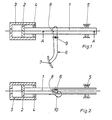
- Fig. 1 eine erfindungsgemäße Ausführung im Querschnitt, wobei die
- Fig. 2 einen Schnitt nach der Linie A -A von Fig- 1 bringt.
- Die Kolbenstange 1 des Kolbens 2 des Hauptbremszylinders 3 wird durch die als Führungen dienenden Ringe 4 und-5 im wesentlichen parallel zur Längsrichtung des Hauptbremszylinders 3 gehalten. Der Ring 4 ist im Zylinder 3 angeordnet, der Ring 5 an einem ortsfesten Teil im Fahrzeug.
- Der Bremshebel 6 mit den Dreh-bzw. Angriffspunkten 8 und 9 weist an einem Ende das Bremspedal 7 auf und ist in der geschlitzt ausgeführten Kolbenstange 1 angelenkt, wie auch die Fig. 2 zeigt, wobei die Blattfeder 10 den Bremshebel und die Kolbenstange aneinanderhält.
- Bei Bremsbetätigung bewegt der Bremshebel 6 die Kolbenstange nach links, wodurch sich Druck aufbaut bzw. erhöht.
- Es ist auch möglich, den Dreh-bzw. Angriffspunkt 9 am oberen Ende des Hebels 6 anzuordnen.
- Da der Hebel 6 angelenkt ist an der Kolbenstange 1 und deren Auslenken durch die Führungen 4 und 5 praktisch nicht möglich ist, kann die Übersetzung von oberen Hebelarm zu unteren Hebelarm des Hebels 6 sehr günstig bemessen werden.
- In Hinblick auf die Reibungsverhältnisse ist es vorteilhaft, an der Berührungsfläche der Kolbenstange 1 bzw. an der Angriffsfläche 8 des Hebels 6 eine Evolventenverzahnung anzubringen. Desgleichen könnte am Hebel 6 eine die Kolbenstange 1 abrollende bzw. daran angelenkte -unter "Anlenken" wird in der gegenständlichen Anmeldung eine gegeneinander verschiebliche, in Bezug auf den Abstand von Angriffsfläche 8 des Hebels 6 zu dessen Drehpunkt 9 eine Veränderung zulassende Verbindung verstanden -Rolle angeordnet sein.
Claims (6)
Applications Claiming Priority (2)
| Application Number | Priority Date | Filing Date | Title |
|---|---|---|---|
| AT1517/85 | 1985-05-21 | ||
| AT151785 | 1985-05-21 |
Publications (2)
| Publication Number | Publication Date |
|---|---|
| EP0203058A2 true EP0203058A2 (de) | 1986-11-26 |
| EP0203058A3 EP0203058A3 (de) | 1987-08-19 |
Family
ID=3515358
Family Applications (1)
| Application Number | Title | Priority Date | Filing Date |
|---|---|---|---|
| EP86890144A Withdrawn EP0203058A3 (de) | 1985-05-21 | 1986-05-20 | Vorrichtung zum Aufbau bzw. Erhöhen eines Druckes in einem Zylinder |
Country Status (9)
| Country | Link |
|---|---|
| EP (1) | EP0203058A3 (de) |
| JP (1) | JPS61271162A (de) |
| DE (1) | DE3616911A1 (de) |
| DK (1) | DK235686D0 (de) |
| ES (1) | ES294262Y (de) |
| FI (1) | FI862224A0 (de) |
| FR (1) | FR2582271A1 (de) |
| GB (1) | GB2177783A (de) |
| SE (1) | SE8602318D0 (de) |
Family Cites Families (13)
| Publication number | Priority date | Publication date | Assignee | Title |
|---|---|---|---|---|
| AT177059B (de) * | 1952-05-06 | 1953-12-28 | Eduard Waschmann | Festhaltevorrichtung für die Fußbremse von Kraftfahrzeugen |
| GB783714A (en) * | 1955-01-14 | 1957-09-25 | Girling Ltd | New or improved control means for a motor vehicle |
| GB877949A (en) * | 1959-07-06 | 1961-09-20 | Cyril Edward Harper | Improvements in or relating to control means for road vehicles |
| US3646831A (en) * | 1970-07-06 | 1972-03-07 | Ford Motor Co | Variable ratio brake pedal |
| US3678779A (en) * | 1970-11-12 | 1972-07-25 | Ford Motor Co | Variable ratio brake pedal |
| US3698260A (en) * | 1971-06-30 | 1972-10-17 | Gen Motors Corp | Vehicle brake control module and pedal lever mounting and hinge means therefor |
| US3739579A (en) * | 1971-07-26 | 1973-06-19 | R Lutz | Hydraulic brake mechanism |
| IT1024546B (it) * | 1974-04-17 | 1978-07-20 | Fasano Osvaldo | Leva a variazione di coppia, causa ta dal aumento della forza resistente delle pompe freno e meccanismi souivalenti degli automezzi esinili |
| FR2278964A1 (fr) * | 1974-07-18 | 1976-02-13 | Peugeot & Renault | Dispositif de commande par pedale a demultiplication variable pour emetteur de pression |
| US4132127A (en) * | 1977-09-06 | 1979-01-02 | The Bendix Corporation | Brake pedal mechanism |
| IT1119004B (it) * | 1979-06-26 | 1986-03-03 | Gonella Piero | Pedale per freno di autoveicolo del tipo a braccio di leva variabile |
| US4385528A (en) * | 1980-10-08 | 1983-05-31 | The Bendix Corporation | Brake pedal linkage assembly |
| DE3305351A1 (de) * | 1983-02-17 | 1984-08-23 | Alfred Teves Gmbh, 6000 Frankfurt | Hydraulische brems- und lenkbremsanlage |
-
1986
- 1986-05-19 GB GB8612167A patent/GB2177783A/en not_active Withdrawn
- 1986-05-20 DE DE19863616911 patent/DE3616911A1/de not_active Withdrawn
- 1986-05-20 EP EP86890144A patent/EP0203058A3/de not_active Withdrawn
- 1986-05-21 JP JP61114986A patent/JPS61271162A/ja active Pending
- 1986-05-21 DK DK235686A patent/DK235686D0/da not_active Application Discontinuation
- 1986-05-21 FR FR8607198A patent/FR2582271A1/fr active Pending
- 1986-05-21 ES ES1986294262U patent/ES294262Y/es not_active Expired
- 1986-05-22 SE SE8602318A patent/SE8602318D0/xx unknown
- 1986-05-27 FI FI862224A patent/FI862224A0/fi not_active Application Discontinuation
Also Published As
| Publication number | Publication date |
|---|---|
| JPS61271162A (ja) | 1986-12-01 |
| ES294262U (es) | 1986-10-16 |
| DK235686D0 (de) | 1986-05-21 |
| EP0203058A3 (de) | 1987-08-19 |
| GB8612167D0 (en) | 1986-06-25 |
| FI862224A0 (fi) | 1986-05-27 |
| GB2177783A (en) | 1987-01-28 |
| SE8602318D0 (sv) | 1986-05-22 |
| DE3616911A1 (de) | 1987-04-23 |
| FR2582271A1 (fr) | 1986-11-28 |
| ES294262Y (es) | 1987-06-16 |
Similar Documents
| Publication | Publication Date | Title |
|---|---|---|
| DE2553228C3 (de) | Mit veränderlicher Übersetzung wirkende Bremsbetätigungsvorrichtung | |
| DE2339534A1 (de) | Steuervorrichtung mit einem einzigen steuerhebel | |
| DE1575872C3 (de) | Betätigungsvorrichtung für das Reibkissen einer Scheibenbremse | |
| DE2131535C3 (de) | Selbsttätige mechanische Nach Stellvorrichtung für eine. Innenback en bremse | |
| DE2730959B2 (de) | Zuspannvorrichtung für Reibungsbremsen, insbesondere von Schienenfahrzeugen | |
| EP0754616B1 (de) | Betätigungsvorrichtung für Seilzüge, insbesondere von Fahrrad- oder Motorradbremsen | |
| DE2220483C3 (de) | Mechanische Betätigungsvorrichtung für eine Innenbacken-Trommelbremse | |
| EP0203058A2 (de) | Vorrichtung zum Aufbau bzw. Erhöhen eines Druckes in einem Zylinder | |
| EP0431382A2 (de) | Zuspanngestänge für Scheibenbremsen | |
| DE2527745C3 (de) | Bremsgestänge für Kraftfahrzeuge oder Anhänger | |
| DE1266066B (de) | Hydraulische oder mechanisch zu betaetigende Teilbelagscheibenbremse | |
| DE2817695A1 (de) | Scheibenbremse | |
| DE3114797A1 (de) | "materialkran mit einer hebezeuglaufkatze" | |
| DE681414C (de) | Scheibenbremse fuer Fahrzeuge | |
| DE3135265A1 (de) | Steuerhebelanordnung zur laengsverschiebung eines stellgliedes | |
| DE1450100A1 (de) | Scheibenbremse | |
| DE2728668C2 (de) | Unterblock für eine Laufkatze | |
| DE3042829C2 (de) | Betätigungsgetriebe für Treibstangenbeschläge o.dgl. | |
| DE3511301C2 (de) | Fahrzeug-Anhängerkupplung | |
| DE2823843A1 (de) | Bremseinrichtung fuer schienenfahrzeuge | |
| DE2457330B2 (de) | Vorrichtung zum öffnen und Schließen der Türe eines Koksofens | |
| DE2107175C3 (de) | Laufwagenzeichenmaschine | |
| DE2225352A1 (de) | Betaetigungsvorrichtung fuer bremsbacken von scheibenbremsen | |
| DE2246071C2 (de) | Bowdenzug | |
| DE3315126C2 (de) | Scheibenwischeranlage, insbesondere Einarm- Scheibenwischeranlage für Kraftwagen |
Legal Events
| Date | Code | Title | Description |
|---|---|---|---|
| PUAI | Public reference made under article 153(3) epc to a published international application that has entered the european phase |
Free format text: ORIGINAL CODE: 0009012 |
|
| AK | Designated contracting states |
Kind code of ref document: A2 Designated state(s): AT BE CH DE FR GB IT LI LU NL SE |
|
| RBV | Designated contracting states (corrected) |
Designated state(s): DE FR GB IT NL SE |
|
| PUAL | Search report despatched |
Free format text: ORIGINAL CODE: 0009013 |
|
| AK | Designated contracting states |
Kind code of ref document: A3 Designated state(s): DE FR GB IT NL SE |
|
| STAA | Information on the status of an ep patent application or granted ep patent |
Free format text: STATUS: THE APPLICATION IS DEEMED TO BE WITHDRAWN |
|
| 18D | Application deemed to be withdrawn |
Effective date: 19891125 |
|
| APAF | Appeal reference modified |
Free format text: ORIGINAL CODE: EPIDOSCREFNE |