EP0201142B1 - Mit einer Bogenheftvorrichtung versehenes Kopiergerät - Google Patents
Mit einer Bogenheftvorrichtung versehenes Kopiergerät Download PDFInfo
- Publication number
- EP0201142B1 EP0201142B1 EP86200795A EP86200795A EP0201142B1 EP 0201142 B1 EP0201142 B1 EP 0201142B1 EP 86200795 A EP86200795 A EP 86200795A EP 86200795 A EP86200795 A EP 86200795A EP 0201142 B1 EP0201142 B1 EP 0201142B1
- Authority
- EP
- European Patent Office
- Prior art keywords
- sheets
- copying machine
- bundle
- opening
- stapler
- Prior art date
- Legal status (The legal status is an assumption and is not a legal conclusion. Google has not performed a legal analysis and makes no representation as to the accuracy of the status listed.)
- Expired
Links
- 230000037431 insertion Effects 0.000 claims 1
- 238000003780 insertion Methods 0.000 claims 1
- 239000011521 glass Substances 0.000 description 13
- 239000000463 material Substances 0.000 description 5
- 238000007599 discharging Methods 0.000 description 4
- 238000005452 bending Methods 0.000 description 1
- 230000006835 compression Effects 0.000 description 1
- 238000007906 compression Methods 0.000 description 1
- 238000001514 detection method Methods 0.000 description 1
- 230000000630 rising effect Effects 0.000 description 1
Images


Classifications
-
- G—PHYSICS
- G03—PHOTOGRAPHY; CINEMATOGRAPHY; ANALOGOUS TECHNIQUES USING WAVES OTHER THAN OPTICAL WAVES; ELECTROGRAPHY; HOLOGRAPHY
- G03G—ELECTROGRAPHY; ELECTROPHOTOGRAPHY; MAGNETOGRAPHY
- G03G15/00—Apparatus for electrographic processes using a charge pattern
- G03G15/65—Apparatus which relate to the handling of copy material
- G03G15/6538—Devices for collating sheet copy material, e.g. sorters, control, copies in staples form
- G03G15/6541—Binding sets of sheets, e.g. by stapling, glueing
-
- G—PHYSICS
- G03—PHOTOGRAPHY; CINEMATOGRAPHY; ANALOGOUS TECHNIQUES USING WAVES OTHER THAN OPTICAL WAVES; ELECTROGRAPHY; HOLOGRAPHY
- G03G—ELECTROGRAPHY; ELECTROPHOTOGRAPHY; MAGNETOGRAPHY
- G03G15/00—Apparatus for electrographic processes using a charge pattern
- G03G15/60—Apparatus which relate to the handling of originals
-
- G—PHYSICS
- G03—PHOTOGRAPHY; CINEMATOGRAPHY; ANALOGOUS TECHNIQUES USING WAVES OTHER THAN OPTICAL WAVES; ELECTROGRAPHY; HOLOGRAPHY
- G03G—ELECTROGRAPHY; ELECTROPHOTOGRAPHY; MAGNETOGRAPHY
- G03G2215/00—Apparatus for electrophotographic processes
- G03G2215/00172—Apparatus for electrophotographic processes relative to the original handling
- G03G2215/00177—Apparatus for electrophotographic processes relative to the original handling for scanning
- G03G2215/00181—Apparatus for electrophotographic processes relative to the original handling for scanning concerning the original's state of motion
- G03G2215/00185—Apparatus for electrophotographic processes relative to the original handling for scanning concerning the original's state of motion original at rest
-
- G—PHYSICS
- G03—PHOTOGRAPHY; CINEMATOGRAPHY; ANALOGOUS TECHNIQUES USING WAVES OTHER THAN OPTICAL WAVES; ELECTROGRAPHY; HOLOGRAPHY
- G03G—ELECTROGRAPHY; ELECTROPHOTOGRAPHY; MAGNETOGRAPHY
- G03G2215/00—Apparatus for electrophotographic processes
- G03G2215/00172—Apparatus for electrophotographic processes relative to the original handling
- G03G2215/0032—Original binding
-
- G—PHYSICS
- G03—PHOTOGRAPHY; CINEMATOGRAPHY; ANALOGOUS TECHNIQUES USING WAVES OTHER THAN OPTICAL WAVES; ELECTROGRAPHY; HOLOGRAPHY
- G03G—ELECTROGRAPHY; ELECTROPHOTOGRAPHY; MAGNETOGRAPHY
- G03G2215/00—Apparatus for electrophotographic processes
- G03G2215/00362—Apparatus for electrophotographic processes relating to the copy medium handling
- G03G2215/00789—Adding properties or qualities to the copy medium
- G03G2215/00822—Binder, e.g. glueing device
- G03G2215/00827—Stapler
-
- G—PHYSICS
- G03—PHOTOGRAPHY; CINEMATOGRAPHY; ANALOGOUS TECHNIQUES USING WAVES OTHER THAN OPTICAL WAVES; ELECTROGRAPHY; HOLOGRAPHY
- G03G—ELECTROGRAPHY; ELECTROPHOTOGRAPHY; MAGNETOGRAPHY
- G03G2215/00—Apparatus for electrophotographic processes
- G03G2215/00362—Apparatus for electrophotographic processes relating to the copy medium handling
- G03G2215/00789—Adding properties or qualities to the copy medium
- G03G2215/00822—Binder, e.g. glueing device
- G03G2215/00856—External binding device
Definitions
- the invention relates to a copying machine provided with a sheet stapler device which comprises a support for collecting sheets printed in the copying machine into a bundle, stapler-means for fastening together a bundle of collected sheets in an edge part thereof, means for feeding the sheets onto and/or from the support through an elongated opening, and an externally accessible opening in the sheet stapler device through which a bundle of sheets can be manually inserted up to the stapler means.
- the object of the present invention is to provide a copying machine of the kind referred to in the preamble, which does not have the drawbacks mentioned hereinbefore.
- the images are applied to the copy sheets in such an orientation that the copies arrive at the collecting point with their sides to be stapled near the operating side of the machine.
- both the stapler means and -the- externally accessible opening can be provided in the copying machine near the operating side of the copying machine, and a bundle of sheets manually introduced can be easily brought in a flat condition up to the stapler means. Since this bundle of sheets has to be inserted through the opening until the stapler means only with the corner area where stapling should take place, in an otherwise arbitrary orientation, it is attained at the same time that the bundle can be stapled at choice along any edge adjacent a corner area.
- the externally accessible opening forms a unity with the elongated opening through which the bundle of collected sheets is discharged from the support, which elongated opening can be closed by a stop for retaining processed sheets fed onto the support, and the stapler means are arranged so that they can staple a bundle of sheets along an edge extending lengthwise of the openings forming a unity.
- the copying machine represented in Fig.1 is provided at the top side with a glass plate 1, upon which an original to be copied can be laid down.
- the glass plate 1 and an original positioned thereon, can be covered by a cover 2 fitted with a conveyor belt for feeding an original onto the glass plate or discharging it from the glass plate.
- An original positioned on the glass plate 1 can be copied on a sheet of receiving material by means of a copying system (not shown).
- An operating panel 3 is placed at the front of the copying machine. Viewed from the operating side of the copying machine a feed tray 4 for a set of originals to be copied is arranged to the right of the glass plate 1.
- a delivering tray 5 is arranged to the left of the glass plate 1.
- the bundle can be inserted outwardly into outlet opening 11, as will be explained in more detail with reference to the Figs. 2 and 3.
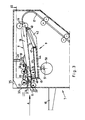
- Unit 7 of the copying machine represented in more detail in the Figs. 2 and 3, comprises an inclined plate 15 forming the bottom of the collecting tray 8.
- Conveyor roller pairs 16 are arranged along the upper edge of plate 15 for feeding copy sheets, coming along path 17 from the copying section of the machine, onto plate 15.
- Openings 22, respectively 23, are formed in the base plate 15 through which openings driven rollers 24, respectively 25 protrude.
- Freely rotable pressure rollers 26, respectively 27, are fitted above these drive rollers, each of the pressure rollers forming a pair with one of the drive rollers 24, respectively 25.
- Each of the pressure roiiers 26 and 27, with the aid of means (not shown). are movable between a position in which they are at some distance above the drive roller with which they form a pair, and a position in which they press on the associated drive roller.
- a stop plate 29 which extends parallel to the axes of the rollers and is connected to an arm 30 being rotatable about a shaft 31, is arranged above plate 15.
- An elongated slot 34 is formed in frame plate 33 at the side of unit 7, and a recess 36, is formed in the frame plate 35 at the front of unit 7, which recess connects to slot 34.
- Slot 34 and recess 36 together form opening 11.
- Plate 15 connects to the frame plates 33 and 35 at the lower edge of slot 34, or recess 36, respectively.
- a stapler device 9 is arranged near the operating side of the copying machine.
- This device known per se and represented schematically in the Figures, comprises a stapling head 40 with a magazine 41 for staple bars, as can be seen in Fig.3, which magazine-is secured between two levers 42 pivotable upon a fixed pin 43 mounted below plate 15 near roller pairs 16.
- An arm 44 also pivotable upon pin 43, is fitted between the levers 42. Arm 44 is supported by a cam roller 50, which can pivot upon a shaft 51 placed excentrically, which shaft via a one-revolution clutch is connected to a drive motor.
- the free end 45 of arm 44 is bent upwardly and forms a buffer for bending a staple bar into a U-shape, for ejecting the resulting staple out of the stapling head 40 and for pushing this staple, at the location indicated with 46 in Fig.2, through a bundle of sheets positioned on plate 15.
- a compression spring 47 mounted between levers 42 and arm 44, keeps the latter at a distance from the foremost staple bar, and upon upward movement of the stapling head compensates for differences in thickness of the bundle of sheets to be stapled.
- the operation of the sheet stapler device is as follows: In the stand-by position of the copying machine the pressure rollers 26 and 27 and the stop plate 29 take up the positions represented in Fig.3 with full lines. In this position of the copying machine it is possible to insert a bundle of sheets from outside into opening 11 until beyond the stapling position 46, as will be explained in detail hereinafter. If the copying machine is set to producing and stapling bundles of copies of a bundle of originals placed in feed tray 4, upon putting the copying machine in operation stop plate 29 is automatically put into the operative position, the stapler motor is switched on, and a first set of copies is made of originals placed in tray 4, which originals after a reproduction has been made are placed back into the tray 4.
- the copies are placed in collecting tray 8 by rollers 16 via path 17, where they are positioned by means of transport wheel 19 against stop plate 29 and wall plate 18, on top of each other on base plate 15.
- the control device of the copying machine energizes the one-revolution clutch between stapler motor and roller shaft 51, in order to activate the stapling head 40.
- the stapling head 40 forces a corner area of the collected set of copy sheets upwardly against anvil 48 and, subsequently, pushes a staple through the sheets.
- the copying machine can also be set to a printing mode in which copies are not collected into sets in tray 8, but are fed directly to tray 10.
- stop plate 29 is kept in the lifted position shown in Fig.3 and the pressure rollers 26, and 27 respectively, are kept in permanent pressure contact with drive rollers 24, and 25, respectively.
- Each copy sheet supplied by rollers 16 is then directly fed over plate 15 into receiving tray 10 by roller pairs 24,26 and 25,27.
Landscapes
- Physics & Mathematics (AREA)
- General Physics & Mathematics (AREA)
- Folding Of Thin Sheet-Like Materials, Special Discharging Devices, And Others (AREA)
- Paper Feeding For Electrophotography (AREA)
Claims (7)
Applications Claiming Priority (2)
| Application Number | Priority Date | Filing Date | Title |
|---|---|---|---|
| NL8501337A NL8501337A (nl) | 1985-05-10 | 1985-05-10 | Kopieerapparaat voorzien van een vellenhechtinrichting. |
| NL8501337 | 1985-05-10 |
Publications (2)
| Publication Number | Publication Date |
|---|---|
| EP0201142A1 EP0201142A1 (de) | 1986-11-12 |
| EP0201142B1 true EP0201142B1 (de) | 1990-08-01 |
Family
ID=19845959
Family Applications (1)
| Application Number | Title | Priority Date | Filing Date |
|---|---|---|---|
| EP86200795A Expired EP0201142B1 (de) | 1985-05-10 | 1986-05-06 | Mit einer Bogenheftvorrichtung versehenes Kopiergerät |
Country Status (5)
| Country | Link |
|---|---|
| US (1) | US4795071A (de) |
| EP (1) | EP0201142B1 (de) |
| JP (1) | JPH0667675B2 (de) |
| DE (1) | DE3673056D1 (de) |
| NL (1) | NL8501337A (de) |
Cited By (1)
| Publication number | Priority date | Publication date | Assignee | Title |
|---|---|---|---|---|
| CN107304011A (zh) * | 2016-04-21 | 2017-10-31 | 株式会社东芝 | 片材后处理装置 |
Families Citing this family (34)
| Publication number | Priority date | Publication date | Assignee | Title |
|---|---|---|---|---|
| DE3724992A1 (de) * | 1986-08-02 | 1988-02-04 | Minolta Camera Kk | Sortier- und bindeeinrichtung fuer kopiergeraete oder dgl. |
| DE3726406A1 (de) * | 1986-08-07 | 1988-02-18 | Minolta Camera Kk | Kopiergeraet mit sortier- und hefteinrichtung |
| US4852867A (en) * | 1986-10-09 | 1989-08-01 | Minolta Camera Kabushiki Kaisha | Copying apparatus having an automatic document feeder with document circulating function and a paper container with paper binding function |
| US5013021A (en) * | 1986-10-16 | 1991-05-07 | Minolta Camera Kabushiki Kaisha | Paper container with a paper binding function |
| US4905053A (en) * | 1987-01-28 | 1990-02-27 | Minolta Camera Kabushiki Kaisha | Sheet re-feeding apparatus provided for image forming apparatus |
| US4901994A (en) * | 1987-07-10 | 1990-02-20 | Minolta Camera Kabushiki Kaisha | Copying apparatus having a sorter with a sheet stapling function |
| US4946153A (en) * | 1987-07-10 | 1990-08-07 | Minolta Camera Kabushiki Kaisha | Paper handling apparatus with a paper stapling function |
| USRE34460E (en) * | 1987-07-10 | 1993-11-30 | Minolta Camera Kabushiki Kaisha | Copying apparatus having a sorter with a sheet stapling function with staple mode cancellation |
| JPH0635221B2 (ja) * | 1987-08-07 | 1994-05-11 | キヤノン株式会社 | シ−ト分類装置 |
| US4958820A (en) * | 1987-08-20 | 1990-09-25 | Minolta Camera Kabushiki Kaisha | Sheet storing apparatus for copying machine |
| JPS6464970A (en) * | 1987-09-04 | 1989-03-10 | Minolta Camera Kk | Sorter provided with finisher |
| US4974823A (en) * | 1988-01-12 | 1990-12-04 | Minolta Camera Kabushiki Kaisha | Sorter-finisher with a sheet binding function and a method of operating thereof |
| US4905055A (en) * | 1988-01-21 | 1990-02-27 | Minolta Camera Kabushiki Kaisha | Copying machine provided with a paper handling device with a paper stapling function |
| US4973036A (en) * | 1988-02-15 | 1990-11-27 | Minolta Camera Kabushiki Kaisha | Sheet handling apparatus provided for a copying machine |
| US4940177A (en) * | 1988-12-30 | 1990-07-10 | Jimena Carlos L | Electric stapler having electronic control circuit |
| US5140380A (en) * | 1989-11-09 | 1992-08-18 | Canon Kabushiki Kaisha | Image forming apparatus with book binding mechanism |
| US5094379A (en) * | 1991-01-25 | 1992-03-10 | Xerox Corporation | Copier with on-line and convenience staplers with shared power supply |
| JP3554632B2 (ja) * | 1996-05-13 | 2004-08-18 | ニスカ株式会社 | 電動ステープラ |
| JP3510746B2 (ja) * | 1996-11-14 | 2004-03-29 | 理想科学工業株式会社 | 電動ステープラ |
| US6099225A (en) * | 1998-09-29 | 2000-08-08 | Hewlett-Packard Company | Booklet maker |
| CN1178800C (zh) * | 1998-09-29 | 2004-12-08 | 惠普公司 | 加工小册子的方法和设备 |
| US6554267B2 (en) | 2001-03-30 | 2003-04-29 | Hewlett-Packard Company | Stapling apparatus for a booklet maker |
| US6632061B2 (en) | 2001-03-30 | 2003-10-14 | Hewlett-Packard Development Company, L.P. | Booklet maker with sheet wise trim |
| US6578838B2 (en) | 2001-03-30 | 2003-06-17 | Hewlett-Packard Development Company, L.P. | Sheet collecting apparatus with integrated staple mechanism |
| US6682285B2 (en) | 2001-03-30 | 2004-01-27 | Hewlett-Packard Development Company L.P. | Sheet-wise hole punching after folding in booklet maker |
| US6966552B2 (en) | 2001-05-14 | 2005-11-22 | Hewlett-Packard Development Company, L.P. | Binding system with sheet-wise formation of features |
| US7197971B2 (en) | 2003-07-18 | 2007-04-03 | Hewlett-Packard Development Company, L.P. | Device for trimming sheet material |
| US6997450B2 (en) * | 2003-10-09 | 2006-02-14 | Hewlett-Packard Development Company, L.P. | Sheet folding and accumulation system for a booklet maker |
| US7101332B2 (en) * | 2003-10-09 | 2006-09-05 | Hewlett-Packard Development Company, L.P. | Sheet folding and trimming apparatus |
| US7311236B2 (en) * | 2005-04-25 | 2007-12-25 | Tsi Manufacturing Llc | Electric stapler having two anvil plates and workpiece sensing controller |
| KR100676852B1 (ko) * | 2005-12-06 | 2007-02-01 | 김호남 | 사무기기용 거치대 어셈블리 |
| WO2018080520A1 (en) * | 2016-10-28 | 2018-05-03 | Hewlett-Packard Development Company, L.P. | Illumuniation source |
| JP6929692B2 (ja) * | 2017-04-27 | 2021-09-01 | キヤノン株式会社 | 後処理装置 |
| JP7224866B2 (ja) * | 2018-11-14 | 2023-02-20 | キヤノン株式会社 | 画像形成システム |
Family Cites Families (5)
| Publication number | Priority date | Publication date | Assignee | Title |
|---|---|---|---|---|
| US4134672A (en) * | 1976-03-30 | 1979-01-16 | Eastman Kodak Company | Copier finisher for an electrographic reproducing device |
| US4184622A (en) * | 1978-07-07 | 1980-01-22 | Xerox Corporation | Stapler head |
| JPS5848059U (ja) * | 1981-09-24 | 1983-03-31 | 株式会社日立製作所 | カセツトドア開閉装置 |
| JPS6067105A (ja) * | 1983-09-22 | 1985-04-17 | キヤノン株式会社 | ステ−ブル綴じ装置 |
| US4575296A (en) * | 1984-05-21 | 1986-03-11 | The Mead Corporation | Apparatus and method for preparing multipage, side-stitched documents |
-
1985
- 1985-05-10 NL NL8501337A patent/NL8501337A/nl not_active Application Discontinuation
-
1986
- 1986-05-06 EP EP86200795A patent/EP0201142B1/de not_active Expired
- 1986-05-06 DE DE8686200795T patent/DE3673056D1/de not_active Expired - Lifetime
- 1986-05-08 JP JP61105776A patent/JPH0667675B2/ja not_active Expired - Fee Related
- 1986-05-09 US US06/861,518 patent/US4795071A/en not_active Expired - Lifetime
Cited By (1)
| Publication number | Priority date | Publication date | Assignee | Title |
|---|---|---|---|---|
| CN107304011A (zh) * | 2016-04-21 | 2017-10-31 | 株式会社东芝 | 片材后处理装置 |
Also Published As
| Publication number | Publication date |
|---|---|
| US4795071A (en) | 1989-01-03 |
| EP0201142A1 (de) | 1986-11-12 |
| DE3673056D1 (de) | 1990-09-06 |
| JPH0667675B2 (ja) | 1994-08-31 |
| JPS61261096A (ja) | 1986-11-19 |
| NL8501337A (nl) | 1986-12-01 |
Similar Documents
| Publication | Publication Date | Title |
|---|---|---|
| EP0201142B1 (de) | Mit einer Bogenheftvorrichtung versehenes Kopiergerät | |
| EP0371403B1 (de) | Vorrichtung zur Bogenweiterverarbeitung und Vorrichtung zur Bilderzeugung | |
| EP0224295B1 (de) | Vorrichtung zum Fördern eines Bogenstapels | |
| JPS6222145B2 (de) | ||
| US5187534A (en) | Stapling device and image forming apparatus having a stapling device | |
| JP3965441B2 (ja) | 用紙仕上げ及び積載装置及び方法 | |
| USRE39168E1 (en) | Image forming apparatus in use with a sheet post-processing apparatus | |
| US3999852A (en) | Copying apparatus capable of both-side printing | |
| GB2228472A (en) | Paper handling apparatus | |
| US4135808A (en) | Document feeder for a copier | |
| CA2008048C (en) | Paper positioning device | |
| JPS60248563A (ja) | シ−ト自動処理装置 | |
| JPH0762768B2 (ja) | 書類シートの送り及び位置決め装置 | |
| US4988030A (en) | Printed recording paper processing apparatus | |
| US5374043A (en) | Sorter with stapler actived release gate mechanism | |
| EP0054351B1 (de) | Endbearbeitungsgerät und dieses enthaltendes Dokumenten-Reproduktions-System | |
| JP3269557B2 (ja) | 複写機用モジュラー仕上げ機 | |
| US20020171192A1 (en) | Stapring apparatus and image forming apparatus | |
| JPH0813584B2 (ja) | 複数の枚葉紙束をステープル止めする方法及びステープラー装置 | |
| JP2568694B2 (ja) | 画像形成装置 | |
| EP0458317B1 (de) | Blattendbearbeitungsgerät | |
| JP3464958B2 (ja) | 排紙装置及びこれを用いた丁合装置並びに画像形成装置 | |
| JP3237391B2 (ja) | シート後処理装置 | |
| JPS5914451Y2 (ja) | 分離爪 | |
| JP2568682B2 (ja) | 画像形成装置 |
Legal Events
| Date | Code | Title | Description |
|---|---|---|---|
| PUAI | Public reference made under article 153(3) epc to a published international application that has entered the european phase |
Free format text: ORIGINAL CODE: 0009012 |
|
| AK | Designated contracting states |
Kind code of ref document: A1 Designated state(s): DE FR GB NL |
|
| PUAB | Information related to the publication of an a document modified or deleted |
Free format text: ORIGINAL CODE: 0009199EPPU |
|
| PUAF | Information related to the publication of a search report (a3 document) modified or deleted |
Free format text: ORIGINAL CODE: 0009199SEPU |
|
| R17D | Deferred search report published (corrected) |
Effective date: 19861217 |
|
| RA1 | Application published (corrected) |
Date of ref document: 19861217 Kind code of ref document: A1 |
|
| 17P | Request for examination filed |
Effective date: 19870701 |
|
| 17Q | First examination report despatched |
Effective date: 19890131 |
|
| GRAA | (expected) grant |
Free format text: ORIGINAL CODE: 0009210 |
|
| AK | Designated contracting states |
Kind code of ref document: B1 Designated state(s): DE FR GB NL |
|
| REF | Corresponds to: |
Ref document number: 3673056 Country of ref document: DE Date of ref document: 19900906 |
|
| ET | Fr: translation filed | ||
| PLBE | No opposition filed within time limit |
Free format text: ORIGINAL CODE: 0009261 |
|
| STAA | Information on the status of an ep patent application or granted ep patent |
Free format text: STATUS: NO OPPOSITION FILED WITHIN TIME LIMIT |
|
| 26N | No opposition filed | ||
| NLT1 | Nl: modifications of names registered in virtue of documents presented to the patent office pursuant to art. 16 a, paragraph 1 |
Owner name: OCE-TECHNOLOGIES B.V. |
|
| REG | Reference to a national code |
Ref country code: GB Ref legal event code: IF02 |
|
| PGFP | Annual fee paid to national office [announced via postgrant information from national office to epo] |
Ref country code: FR Payment date: 20040408 Year of fee payment: 19 |
|
| PGFP | Annual fee paid to national office [announced via postgrant information from national office to epo] |
Ref country code: GB Payment date: 20040415 Year of fee payment: 19 |
|
| PGFP | Annual fee paid to national office [announced via postgrant information from national office to epo] |
Ref country code: DE Payment date: 20040422 Year of fee payment: 19 |
|
| PGFP | Annual fee paid to national office [announced via postgrant information from national office to epo] |
Ref country code: NL Payment date: 20040518 Year of fee payment: 19 |
|
| PG25 | Lapsed in a contracting state [announced via postgrant information from national office to epo] |
Ref country code: GB Free format text: LAPSE BECAUSE OF NON-PAYMENT OF DUE FEES Effective date: 20050506 |
|
| PG25 | Lapsed in a contracting state [announced via postgrant information from national office to epo] |
Ref country code: NL Free format text: LAPSE BECAUSE OF NON-PAYMENT OF DUE FEES Effective date: 20051201 Ref country code: DE Free format text: LAPSE BECAUSE OF NON-PAYMENT OF DUE FEES Effective date: 20051201 |
|
| GBPC | Gb: european patent ceased through non-payment of renewal fee |
Effective date: 20050506 |
|
| PG25 | Lapsed in a contracting state [announced via postgrant information from national office to epo] |
Ref country code: FR Free format text: LAPSE BECAUSE OF NON-PAYMENT OF DUE FEES Effective date: 20060131 |
|
| NLV4 | Nl: lapsed or anulled due to non-payment of the annual fee |
Effective date: 20051201 |
|
| REG | Reference to a national code |
Ref country code: FR Ref legal event code: ST Effective date: 20060131 |