EP0199893B1 - Deckenschalung - Google Patents
Deckenschalung Download PDFInfo
- Publication number
- EP0199893B1 EP0199893B1 EP86100981A EP86100981A EP0199893B1 EP 0199893 B1 EP0199893 B1 EP 0199893B1 EP 86100981 A EP86100981 A EP 86100981A EP 86100981 A EP86100981 A EP 86100981A EP 0199893 B1 EP0199893 B1 EP 0199893B1
- Authority
- EP
- European Patent Office
- Prior art keywords
- girder
- shuttering
- ceilings
- flange
- bearing head
- Prior art date
- Legal status (The legal status is an assumption and is not a legal conclusion. Google has not performed a legal analysis and makes no representation as to the accuracy of the status listed.)
- Expired
Links
- 238000009416 shuttering Methods 0.000 title claims abstract description 19
- 238000009415 formwork Methods 0.000 claims abstract description 47
- 238000004873 anchoring Methods 0.000 claims abstract description 3
- 230000000284 resting effect Effects 0.000 claims abstract 2
- 238000003780 insertion Methods 0.000 claims description 2
- 230000037431 insertion Effects 0.000 claims description 2
- 239000000725 suspension Substances 0.000 description 9
- 238000004519 manufacturing process Methods 0.000 description 2
- 238000005452 bending Methods 0.000 description 1
- 239000002131 composite material Substances 0.000 description 1
- 230000008878 coupling Effects 0.000 description 1
- 238000010168 coupling process Methods 0.000 description 1
- 238000005859 coupling reaction Methods 0.000 description 1
- 230000003993 interaction Effects 0.000 description 1
- 238000000034 method Methods 0.000 description 1
- 230000000717 retained effect Effects 0.000 description 1
Images


Classifications
-
- E—FIXED CONSTRUCTIONS
- E04—BUILDING
- E04G—SCAFFOLDING; FORMS; SHUTTERING; BUILDING IMPLEMENTS OR AIDS, OR THEIR USE; HANDLING BUILDING MATERIALS ON THE SITE; REPAIRING, BREAKING-UP OR OTHER WORK ON EXISTING BUILDINGS
- E04G11/00—Forms, shutterings, or falsework for making walls, floors, ceilings, or roofs
- E04G11/36—Forms, shutterings, or falsework for making walls, floors, ceilings, or roofs for floors, ceilings, or roofs of plane or curved surfaces end formpanels for floor shutterings
- E04G11/48—Supporting structures for shutterings or frames for floors or roofs
- E04G11/486—Dropheads supporting the concrete after removal of the shuttering; Connecting means on beams specially adapted for dropheads
-
- E—FIXED CONSTRUCTIONS
- E04—BUILDING
- E04G—SCAFFOLDING; FORMS; SHUTTERING; BUILDING IMPLEMENTS OR AIDS, OR THEIR USE; HANDLING BUILDING MATERIALS ON THE SITE; REPAIRING, BREAKING-UP OR OTHER WORK ON EXISTING BUILDINGS
- E04G11/00—Forms, shutterings, or falsework for making walls, floors, ceilings, or roofs
- E04G11/36—Forms, shutterings, or falsework for making walls, floors, ceilings, or roofs for floors, ceilings, or roofs of plane or curved surfaces end formpanels for floor shutterings
- E04G11/38—Forms, shutterings, or falsework for making walls, floors, ceilings, or roofs for floors, ceilings, or roofs of plane or curved surfaces end formpanels for floor shutterings for plane ceilings of concrete
-
- E—FIXED CONSTRUCTIONS
- E04—BUILDING
- E04G—SCAFFOLDING; FORMS; SHUTTERING; BUILDING IMPLEMENTS OR AIDS, OR THEIR USE; HANDLING BUILDING MATERIALS ON THE SITE; REPAIRING, BREAKING-UP OR OTHER WORK ON EXISTING BUILDINGS
- E04G11/00—Forms, shutterings, or falsework for making walls, floors, ceilings, or roofs
- E04G11/36—Forms, shutterings, or falsework for making walls, floors, ceilings, or roofs for floors, ceilings, or roofs of plane or curved surfaces end formpanels for floor shutterings
- E04G11/48—Supporting structures for shutterings or frames for floors or roofs
- E04G11/483—Supporting heads
Definitions
- the invention relates to a slab formwork with a formwork plate at its upper end supports, the supports connecting beams and between the beams with these flush-mounted formwork panels, the edges of which bear against the edges of the beams in the use position, the supports also when shuttering and stripping have fixed, non-adjustable support head with a fastening device arranged under its formwork panel for attacking the formwork girders by means of a detachably connectable flange or fastening attachment.
- Such slab formwork is known from DE-C-3003682.
- the ends of the supports each have a flange which engages under the underside of the fastening device of the support head and can be releasably connected to it, so that the connecting means, preferably connecting bolts, must be inserted vertically through this flange from below.
- the connecting bolt itself is only subjected to tension, the use of such connecting bolts with transverse pins, which are inserted through keyhole-like perforations, results in a load of the transverse pins on shear in the rotated position.
- tension in the perforations which are penetrated at the same time can prevent the bolt from being easily pulled out, although these bolts are rotatable.
- the solution to this problem consists essentially in that the support head on at least one side and the support only on that side of the support head facing side have a hook-in connection with which the carrier is pivotally attached to the support and guided by the hook-in connection in its use - And the fastening position can be swiveled up, in which the end of the carrier opposite the hook-in connection has an anchoring fastening device with its flange with the next support head.
- DE-C-2311544 already discloses a suspension connection between the support head and the support for a support device for formwork beams of a ceiling formwork of another type.
- this hook-in connection is provided at both ends of the carrier as a single attachment and a groove lying on a concentric circle is necessary on the support head and a corresponding projection on the carrier for engaging in this groove, which due to manufacturing tolerances leads to inaccuracies in the alignment of the wearer through lateral play against the support head.
- the carrier is only securely attached to the support head when the entire formwork composite has been produced, i. H. During stripping and later when stripping formwork panels, beams are exposed, which then only lie loosely in their hanging grooves.
- a slab formwork system of another type in which the beam is coupled to a support head via a hanging connection, but the support head is adjustable in height so that after hanging the support head with the support is moved upwards in the position of use and is moved down again for stripping.
- hook-in connections that is to say not at least one fastening flange in accordance with the solution according to the invention, are provided at both ends of the carrier and in corresponding locations on the support heads.
- a particularly secure and precise fixing of the support is obtained if the support and the support head have a flange connection which can be locked in the position of use of the support, even in the region of their suspension connection.
- the hook-in connection then serves above all for easy striking and stripping of the beam, because the beam can initially be temporarily fixed on one side, then locked on the opposite side and finally locked in the area of the hook-in connection. In Ge then the forces are absorbed by the flange connections.
- the support head can have a hanging device for a swivel connection on its two opposite connection end faces for supports. This has the advantage that the user does not have to pay attention to whether the respective support head with its hooking device is correctly oriented, since a rotated position by 180 ° also fits a corresponding carrier.
- An embodiment of the invention of considerable importance which above all makes it easier to remove formwork even with somewhat jammed fastening bolts, can consist in that the flanges on the support head and support run in cross-section from top to bottom. This gives the fastening bolts an approximately parallel or only slightly oblique orientation to the formlining, so that their ends can be acted upon by a striking tool should a bolt ever become jammed. This arrangement is therefore of greater importance for the simplification of the formwork work.
- the fastening or locking bolts themselves are subjected to shear in such a locking, the bolts themselves being able to absorb greater shear forces than their transverse pins.
- a very special embodiment of the ceiling formwork of the type mentioned at the outset can consist in that the fastening flange of the support head, starting from its formwork plate, is inclined obliquely towards the support and the corresponding front flange of the support has a corresponding bevel, the flanges of the support head lying opposite one another are arranged closer to each other with their lower edges than with their upper edges.
- the connecting bolts are given a slightly oblique course, which does not impair the simplicity of the stripping process and furthermore enables the use of an impact tool, but makes insertion a little more convenient from the bottom up.
- Embodiments of the invention in particular with regard to the suspension connection, are the subject of claims 5 to 16.
- a ceiling formwork results in which the advantages of the ceiling formwork according to DE-C-3003682 are largely retained, but the additional formwork means that the formwork is removed and removed Hanging connection can be carried out by a single person.
- the second person who has to hold the girder with the known slab formwork, is practically replaced by the hanging connection. Nevertheless, the risk of accidents is also reduced because the hook-in connection can be designed accordingly safely and mutual consideration of two operators is avoided.
- a ceiling formwork designated as a whole has supports 2 which have a formwork panel 3 at their upper end.
- the support 2 in the exemplary embodiment has a support head, generally designated 4, which on its underside below its formwork plate 3 has a plug-in attachment 5 for coupling with the actual support 2, as is indicated in FIG.
- the slab formwork 1 also includes the supports 2 with the support heads 4 connecting supports 6 and also between the supports 6, which can be fastened in alignment with them and not shown in the drawing, the edges of which rest against the edges or edge webs 7 of the support 6 in the use position.
- the support head 4 has fastening devices for attacking the formwork girders, which in turn has releasably connectable flanges 8 'as a fastening attachment.
- the fastening bolts 9 used to connect the flanges can run largely horizontally or in any case in such a way that their end faces opposite to their bolt heads 10 remain accessible for a striking tool, which makes stripping easier, even if a bolt 9 should be jammed inside the connection perforations 11.
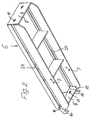
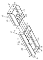
- the support head 4 and the support 6 have a suspension connection 12 with one another on a facing end face, the individual parts of which can be seen in FIGS. 1 to 3 and whose interaction can be seen in FIG. 4.
- the support 6 can be pivotally fixed at least temporarily on the support 2 or the support head 4.
- This suspension connection 12 also allows the support to be swiveled up into the use and fastening position shown in FIG. 4, the suspension connection 12 guiding the support so that it is in the desired aligned position in relation to the next support 2 and the support head 4 arrives.
- the end of the carrier opposite the hook-in connection 12 can be connected with its flange 8 ′ to the next support head 4.
- the support 6 and the support head 4 also have a flange connection which can be locked in the position of use of the support 6 by means of bolts 9 in the region of their suspension connection 12.
- the support head 4 has on each of its two opposite connection end faces for support 6 a suspension device to be described for the hook connection 12.
- a holding bolt 13 running transversely to the pivoting direction and the orientation of the support 6 and on the counterpart a matching hook 14 serving to overlap the holding bolt 13, the hook opening of which according to FIG. 4 and also according to FIGS 2 and 3 points essentially downwards.
- the pivot axis 15 of the hook-in connection 12 is located below the flange connection and its locking attachment, as shown in FIG. 4, approximately at the level of the lower edge 8a of the flange 8. This makes it easily possible to mount a bracket 6 on its hook-in connection 12 after loosening the flange connections to pivot downward, whereby the flanges 8 and 8 'in the region of the hook-in connection 12 also detach from one another.
- the support head 4 can also be used very close to a wall without protruding hooks protruding from it.
- the one or more retaining bolts 13 of the hook-in connection is arranged below the outline of the formwork panel 3 of the support head 4.
- the flange 8 of the support head 4 has recesses 16 in its area higher than the one or the retaining bolts 13, in the exemplary embodiment slots for inserting the hooks 14.
- the flange 8 of the support head 4 has two slots 16 for the passage of these hooks 14.
- At least one continuous retaining bolt 13 running parallel to the plane of the fastening flange 8 could be provided on the support head 4.
- the flange 8 of the support head 4 is inclined somewhat obliquely towards the support.
- the corresponding frontal flange 8 'of the carrier 6 has a corresponding inclination or inclination, the flanges 8 of the support head 4 lying opposite one another being arranged closer to one another with their lower wheels 8a than with their upper edges in the area of their formwork panel 3. This gives the frontal sides Flanges 8 'of the carrier 6 already from the outset the inclination which they would also receive when swiveling downward about the hook-in connection 12 and which, in the inclined position provided, only needs to be increased in the use position.
- the hooks 14 of the hook-in connection 12 are arranged directly on the inner sides of the side webs 18 of the carrier 6 and that accordingly the hook-in slots 16 are also provided in the end flanges 8 directly next to the side walls 17 of the support head 4 are.
- the bolts 13 are least stressed on bending.
- the carrier 6 can have a part 19 which can be pulled out in its longitudinal direction, the hooks 14 in this case being arranged on the guide body 20 of the carrier holding the pull-out part 19.
- the user can first hang this extendable carrier 6 on a support head 4 and then pull out the extendable part 19 to the required length up to the next support head 4 and fasten it there.
- a box-shaped extension 23 with an end flange 8 ' is provided on the extendable part 19 of the telescopically extendable carrier 6 in the region of an end piece 22 which closes the guide tube 21 of this extendable part 19 and which has the end flange 8', which the fastening device, in the exemplary embodiment has keyhole-like perforations 11 for connection to the support head 4 and its flange 8 and is at a distance from the end face of the guide tube or tubes 21.
- keyhole-like perforations 11 and cross pins having fastening bolts 9 are provided for connecting the flanges 8 and 8 'and for locking them as fastening points, which are indicated in FIG. 4.
Landscapes
- Architecture (AREA)
- Engineering & Computer Science (AREA)
- Mechanical Engineering (AREA)
- Civil Engineering (AREA)
- Structural Engineering (AREA)
- Forms Removed On Construction Sites Or Auxiliary Members Thereof (AREA)
- Curing Cements, Concrete, And Artificial Stone (AREA)
- Treatment Of Sludge (AREA)
- Compounds Of Unknown Constitution (AREA)
- Lubricants (AREA)
- Optical Communication System (AREA)
- Body Washing Hand Wipes And Brushes (AREA)
- Farming Of Fish And Shellfish (AREA)
- Polysaccharides And Polysaccharide Derivatives (AREA)
- Polyesters Or Polycarbonates (AREA)
- Artificial Fish Reefs (AREA)
- Vehicle Interior And Exterior Ornaments, Soundproofing, And Insulation (AREA)
- Seats For Vehicles (AREA)
Priority Applications (1)
| Application Number | Priority Date | Filing Date | Title |
|---|---|---|---|
| AT86100981T ATE47453T1 (de) | 1985-04-27 | 1986-01-24 | Deckenschalung. |
Applications Claiming Priority (2)
| Application Number | Priority Date | Filing Date | Title |
|---|---|---|---|
| DE19853515322 DE3515322A1 (de) | 1985-04-27 | 1985-04-27 | Deckenschalung |
| DE3515322 | 1985-04-27 |
Publications (3)
| Publication Number | Publication Date |
|---|---|
| EP0199893A2 EP0199893A2 (de) | 1986-11-05 |
| EP0199893A3 EP0199893A3 (en) | 1987-05-20 |
| EP0199893B1 true EP0199893B1 (de) | 1989-10-18 |
Family
ID=6269333
Family Applications (1)
| Application Number | Title | Priority Date | Filing Date |
|---|---|---|---|
| EP86100981A Expired EP0199893B1 (de) | 1985-04-27 | 1986-01-24 | Deckenschalung |
Country Status (9)
| Country | Link |
|---|---|
| EP (1) | EP0199893B1 (da) |
| AT (1) | ATE47453T1 (da) |
| AU (1) | AU576670B2 (da) |
| DE (2) | DE3515322A1 (da) |
| DK (1) | DK161900C (da) |
| ES (1) | ES296634Y (da) |
| NO (1) | NO861640L (da) |
| PT (1) | PT82459B (da) |
| ZA (1) | ZA859289B (da) |
Families Citing this family (7)
| Publication number | Priority date | Publication date | Assignee | Title |
|---|---|---|---|---|
| DE4237514A1 (de) * | 1992-11-06 | 1994-05-11 | Peri Bv | Stütze mit abnehmbarem Stützenkopf |
| DE102004004883B4 (de) | 2003-08-04 | 2021-10-14 | Friedrich Ischebeck Gmbh | Deckenschalungs-Paneel und System-Deckenschalung |
| DE102006015348A1 (de) * | 2006-04-03 | 2007-10-04 | Peri Gmbh | Deckenschalungssystem |
| ITPD20120411A1 (it) * | 2012-12-28 | 2014-06-29 | Faresin Building Division S P A | Struttura perfezionata di casseratura per l'esecuzione di getti orizzontali per la realizzazione di solai |
| ITPR20130047A1 (it) * | 2013-05-31 | 2014-12-01 | Tecnotelai Components S R L | Sistema e metodo per la realizzazione di una sovrastruttura |
| ES2527895B1 (es) * | 2013-07-29 | 2015-11-05 | Inveral, S.A. | Encofrado para una viga de cuelgue |
| DE102018118230A1 (de) * | 2018-07-27 | 2020-01-30 | Peri Gmbh | Lagerkopf mit abspanntraverse und damit verbundenes deckenschalungssystem |
Family Cites Families (7)
| Publication number | Priority date | Publication date | Assignee | Title |
|---|---|---|---|---|
| CH433685A (de) * | 1965-07-21 | 1967-04-15 | Enzmann Fritz | Vorfabrizierte Schalung zur Erstellung von Betondecken und Betonwänden |
| GB2005332B (en) * | 1977-09-21 | 1982-03-24 | Rapid Metal Developments Ltd | Formword support system |
| DE2927116A1 (de) * | 1979-07-05 | 1981-01-08 | Noe Schaltechnik Gmbh | Deckenschalungssystem mit einer absenkkopf-stuetzanordnung |
| NO801984L (no) * | 1979-07-14 | 1981-01-15 | Sgb Group Ltd | Anordning ved forskalingssystem. |
| DE3003682C2 (de) * | 1980-02-01 | 1983-12-22 | Josef 7611 Steinach Maier | Deckenschalung |
| DE3215002A1 (de) * | 1982-04-22 | 1983-10-27 | Emil Steidle Gmbh & Co, 7480 Sigmaringen | Baustuetze |
| DE3316557C1 (de) * | 1983-03-03 | 1984-10-11 | NOE-Schaltechnik GmbH, 7334 Süssen | Deckenschalungssystem |
-
1985
- 1985-04-27 DE DE19853515322 patent/DE3515322A1/de active Granted
- 1985-12-04 ZA ZA859289A patent/ZA859289B/xx unknown
-
1986
- 1986-01-24 EP EP86100981A patent/EP0199893B1/de not_active Expired
- 1986-01-24 DE DE8686100981T patent/DE3666480D1/de not_active Expired
- 1986-01-24 AT AT86100981T patent/ATE47453T1/de not_active IP Right Cessation
- 1986-02-28 AU AU54192/86A patent/AU576670B2/en not_active Ceased
- 1986-04-03 ES ES1986296634U patent/ES296634Y/es not_active Expired
- 1986-04-16 DK DK174286A patent/DK161900C/da active IP Right Grant
- 1986-04-24 PT PT82459A patent/PT82459B/pt not_active IP Right Cessation
- 1986-04-25 NO NO861640A patent/NO861640L/no unknown
Also Published As
| Publication number | Publication date |
|---|---|
| DE3666480D1 (en) | 1989-11-23 |
| ES296634Y (es) | 1988-05-16 |
| AU5419286A (en) | 1986-10-30 |
| DK161900B (da) | 1991-08-26 |
| DK161900C (da) | 1992-02-17 |
| EP0199893A2 (de) | 1986-11-05 |
| AU576670B2 (en) | 1988-09-01 |
| NO861640L (no) | 1986-10-28 |
| ES296634U (es) | 1987-12-01 |
| DK174286A (da) | 1986-10-28 |
| PT82459A (de) | 1986-05-01 |
| DE3515322A1 (de) | 1986-10-30 |
| EP0199893A3 (en) | 1987-05-20 |
| ZA859289B (en) | 1986-11-26 |
| PT82459B (pt) | 1992-07-31 |
| DE3515322C2 (da) | 1988-07-14 |
| DK174286D0 (da) | 1986-04-16 |
| ATE47453T1 (de) | 1989-11-15 |
Similar Documents
| Publication | Publication Date | Title |
|---|---|---|
| EP0918912B2 (de) | Zerlegbares fassadengerüst | |
| DE3004245C2 (de) | Deckenschalung mit Fallköpfen | |
| DE2838711A1 (de) | Stapelbarer behaelter aus stahldrahtgitter mit klappbaren waenden | |
| EP3702550A1 (de) | Schalungsrahmen, schalungselement, deckenschalung und verfahren | |
| EP2679744A1 (de) | Betonierungs-Deckenschalung | |
| EP0211172B1 (de) | Unterdecke | |
| DE3515322C2 (da) | ||
| DE3603453A1 (de) | Stell- oder trennwand | |
| EP0611257B1 (de) | Kletterkonsole | |
| EP0370034A1 (de) | Verbindungsvorrichtung für schaltafeln. | |
| DE3838489C1 (da) | ||
| DE9005901U1 (de) | Deckenschalungssystem, insbesondere zum Herstellen von Betondecken | |
| DE102021101679A1 (de) | Vorrichtung zur Anbringung einer Deckenschalplatte, Deckenschalung, Deckenpaneel für eine Deckenschalung, Trägerleiste, Trägereinheit, Trägeranschluss und Trägerhalter | |
| DE3401873A1 (de) | Vorrichtung zur haengenden befestigung eines geruestelements | |
| EP0119379B1 (de) | Arbeitsbühne | |
| DE3024580A1 (de) | Halterung fuer deckenschalelemente | |
| DE69015976T2 (de) | Baugerüst. | |
| DE3639129C2 (da) | ||
| DE802280C (de) | Baugeruest | |
| DE728700C (de) | Konstruktionsglieder fuer montierfertige Holzhaeuser | |
| EP0360001A1 (de) | Vorrichtung zum Befestigen von Platten an einer Wand, insbesondere Keramikplatten | |
| EP0331796A1 (de) | Verstärkte Aufhängevorrichtung für Kabel | |
| DE29705696U1 (de) | Vorrichtung zur Vereinfachung der Ein- und Ausschalung von Deckenflächen im Hoch- und Tiefbau | |
| DE4316976A1 (de) | Gerüstbühne | |
| EP0197248B1 (de) | Unterzugschalung |
Legal Events
| Date | Code | Title | Description |
|---|---|---|---|
| PUAI | Public reference made under article 153(3) epc to a published international application that has entered the european phase |
Free format text: ORIGINAL CODE: 0009012 |
|
| AK | Designated contracting states |
Kind code of ref document: A2 Designated state(s): AT BE CH DE FR GB IT LI LU NL SE |
|
| PUAL | Search report despatched |
Free format text: ORIGINAL CODE: 0009013 |
|
| AK | Designated contracting states |
Kind code of ref document: A3 Designated state(s): AT BE CH DE FR GB IT LI LU NL SE |
|
| 17P | Request for examination filed |
Effective date: 19870619 |
|
| 17Q | First examination report despatched |
Effective date: 19880928 |
|
| GRAA | (expected) grant |
Free format text: ORIGINAL CODE: 0009210 |
|
| ITF | It: translation for a ep patent filed | ||
| AK | Designated contracting states |
Kind code of ref document: B1 Designated state(s): AT BE CH DE FR GB IT LI LU NL SE |
|
| REF | Corresponds to: |
Ref document number: 47453 Country of ref document: AT Date of ref document: 19891115 Kind code of ref document: T |
|
| REF | Corresponds to: |
Ref document number: 3666480 Country of ref document: DE Date of ref document: 19891123 |
|
| GBT | Gb: translation of ep patent filed (gb section 77(6)(a)/1977) | ||
| ET | Fr: translation filed | ||
| PLBE | No opposition filed within time limit |
Free format text: ORIGINAL CODE: 0009261 |
|
| STAA | Information on the status of an ep patent application or granted ep patent |
Free format text: STATUS: NO OPPOSITION FILED WITHIN TIME LIMIT |
|
| 26N | No opposition filed | ||
| ITTA | It: last paid annual fee | ||
| PGFP | Annual fee paid to national office [announced via postgrant information from national office to epo] |
Ref country code: LU Payment date: 19940131 Year of fee payment: 9 |
|
| PGFP | Annual fee paid to national office [announced via postgrant information from national office to epo] |
Ref country code: SE Payment date: 19950123 Year of fee payment: 10 |
|
| PG25 | Lapsed in a contracting state [announced via postgrant information from national office to epo] |
Ref country code: LU Free format text: LAPSE BECAUSE OF NON-PAYMENT OF DUE FEES Effective date: 19950124 |
|
| EAL | Se: european patent in force in sweden |
Ref document number: 86100981.9 |
|
| PGFP | Annual fee paid to national office [announced via postgrant information from national office to epo] |
Ref country code: GB Payment date: 19960119 Year of fee payment: 11 |
|
| PG25 | Lapsed in a contracting state [announced via postgrant information from national office to epo] |
Ref country code: SE Effective date: 19960125 |
|
| PGFP | Annual fee paid to national office [announced via postgrant information from national office to epo] |
Ref country code: NL Payment date: 19960131 Year of fee payment: 11 Ref country code: AT Payment date: 19960131 Year of fee payment: 11 |
|
| PGFP | Annual fee paid to national office [announced via postgrant information from national office to epo] |
Ref country code: BE Payment date: 19960305 Year of fee payment: 11 |
|
| EUG | Se: european patent has lapsed |
Ref document number: 86100981.9 |
|
| PG25 | Lapsed in a contracting state [announced via postgrant information from national office to epo] |
Ref country code: GB Effective date: 19970124 Ref country code: AT Effective date: 19970124 |
|
| PG25 | Lapsed in a contracting state [announced via postgrant information from national office to epo] |
Ref country code: BE Effective date: 19970131 |
|
| BERE | Be: lapsed |
Owner name: MAIER JOSEPH Effective date: 19970131 |
|
| PG25 | Lapsed in a contracting state [announced via postgrant information from national office to epo] |
Ref country code: NL Effective date: 19970801 |
|
| GBPC | Gb: european patent ceased through non-payment of renewal fee |
Effective date: 19970124 |
|
| NLV4 | Nl: lapsed or anulled due to non-payment of the annual fee |
Effective date: 19970801 |
|
| PGFP | Annual fee paid to national office [announced via postgrant information from national office to epo] |
Ref country code: CH Payment date: 19990201 Year of fee payment: 14 |
|
| PG25 | Lapsed in a contracting state [announced via postgrant information from national office to epo] |
Ref country code: LI Free format text: LAPSE BECAUSE OF NON-PAYMENT OF DUE FEES Effective date: 20000131 Ref country code: CH Free format text: LAPSE BECAUSE OF NON-PAYMENT OF DUE FEES Effective date: 20000131 |
|
| REG | Reference to a national code |
Ref country code: CH Ref legal event code: PL |
|
| PGFP | Annual fee paid to national office [announced via postgrant information from national office to epo] |
Ref country code: FR Payment date: 20011221 Year of fee payment: 17 Ref country code: DE Payment date: 20011221 Year of fee payment: 17 |
|
| PG25 | Lapsed in a contracting state [announced via postgrant information from national office to epo] |
Ref country code: DE Free format text: LAPSE BECAUSE OF NON-PAYMENT OF DUE FEES Effective date: 20030801 |
|
| PG25 | Lapsed in a contracting state [announced via postgrant information from national office to epo] |
Ref country code: FR Free format text: LAPSE BECAUSE OF NON-PAYMENT OF DUE FEES Effective date: 20030930 |
|
| REG | Reference to a national code |
Ref country code: FR Ref legal event code: ST |
|
| PG25 | Lapsed in a contracting state [announced via postgrant information from national office to epo] |
Ref country code: IT Free format text: LAPSE BECAUSE OF NON-PAYMENT OF DUE FEES Effective date: 20050124 |