EP0199270A2 - Dispositif pour maintenir une porte ou une fenêtre entrouverte dans au moins une position - Google Patents
Dispositif pour maintenir une porte ou une fenêtre entrouverte dans au moins une position Download PDFInfo
- Publication number
- EP0199270A2 EP0199270A2 EP86105215A EP86105215A EP0199270A2 EP 0199270 A2 EP0199270 A2 EP 0199270A2 EP 86105215 A EP86105215 A EP 86105215A EP 86105215 A EP86105215 A EP 86105215A EP 0199270 A2 EP0199270 A2 EP 0199270A2
- Authority
- EP
- European Patent Office
- Prior art keywords
- locking
- housing
- pin
- locking device
- window
- Prior art date
- Legal status (The legal status is an assumption and is not a legal conclusion. Google has not performed a legal analysis and makes no representation as to the accuracy of the status listed.)
- Granted
Links
Images


Classifications
-
- E—FIXED CONSTRUCTIONS
- E05—LOCKS; KEYS; WINDOW OR DOOR FITTINGS; SAFES
- E05C—BOLTS OR FASTENING DEVICES FOR WINGS, SPECIALLY FOR DOORS OR WINDOWS
- E05C17/00—Devices for holding wings open; Devices for limiting opening of wings or for holding wings open by a movable member extending between frame and wing; Braking devices, stops or buffers, combined therewith
- E05C17/02—Devices for holding wings open; Devices for limiting opening of wings or for holding wings open by a movable member extending between frame and wing; Braking devices, stops or buffers, combined therewith by mechanical means
- E05C17/04—Devices for holding wings open; Devices for limiting opening of wings or for holding wings open by a movable member extending between frame and wing; Braking devices, stops or buffers, combined therewith by mechanical means with a movable bar or equivalent member extending between frame and wing
- E05C17/12—Devices for holding wings open; Devices for limiting opening of wings or for holding wings open by a movable member extending between frame and wing; Braking devices, stops or buffers, combined therewith by mechanical means with a movable bar or equivalent member extending between frame and wing consisting of a single rod
- E05C17/16—Devices for holding wings open; Devices for limiting opening of wings or for holding wings open by a movable member extending between frame and wing; Braking devices, stops or buffers, combined therewith by mechanical means with a movable bar or equivalent member extending between frame and wing consisting of a single rod pivoted only at one end and having an elongated slot
-
- E—FIXED CONSTRUCTIONS
- E05—LOCKS; KEYS; WINDOW OR DOOR FITTINGS; SAFES
- E05C—BOLTS OR FASTENING DEVICES FOR WINGS, SPECIALLY FOR DOORS OR WINDOWS
- E05C17/00—Devices for holding wings open; Devices for limiting opening of wings or for holding wings open by a movable member extending between frame and wing; Braking devices, stops or buffers, combined therewith
- E05C17/02—Devices for holding wings open; Devices for limiting opening of wings or for holding wings open by a movable member extending between frame and wing; Braking devices, stops or buffers, combined therewith by mechanical means
- E05C17/04—Devices for holding wings open; Devices for limiting opening of wings or for holding wings open by a movable member extending between frame and wing; Braking devices, stops or buffers, combined therewith by mechanical means with a movable bar or equivalent member extending between frame and wing
- E05C17/12—Devices for holding wings open; Devices for limiting opening of wings or for holding wings open by a movable member extending between frame and wing; Braking devices, stops or buffers, combined therewith by mechanical means with a movable bar or equivalent member extending between frame and wing consisting of a single rod
- E05C17/24—Devices for holding wings open; Devices for limiting opening of wings or for holding wings open by a movable member extending between frame and wing; Braking devices, stops or buffers, combined therewith by mechanical means with a movable bar or equivalent member extending between frame and wing consisting of a single rod pivoted at one end, and with the other end running along a guide member
- E05C17/28—Devices for holding wings open; Devices for limiting opening of wings or for holding wings open by a movable member extending between frame and wing; Braking devices, stops or buffers, combined therewith by mechanical means with a movable bar or equivalent member extending between frame and wing consisting of a single rod pivoted at one end, and with the other end running along a guide member with braking, clamping or securing means at the connection to the guide member
-
- E—FIXED CONSTRUCTIONS
- E05—LOCKS; KEYS; WINDOW OR DOOR FITTINGS; SAFES
- E05C—BOLTS OR FASTENING DEVICES FOR WINGS, SPECIALLY FOR DOORS OR WINDOWS
- E05C17/00—Devices for holding wings open; Devices for limiting opening of wings or for holding wings open by a movable member extending between frame and wing; Braking devices, stops or buffers, combined therewith
- E05C17/02—Devices for holding wings open; Devices for limiting opening of wings or for holding wings open by a movable member extending between frame and wing; Braking devices, stops or buffers, combined therewith by mechanical means
- E05C17/04—Devices for holding wings open; Devices for limiting opening of wings or for holding wings open by a movable member extending between frame and wing; Braking devices, stops or buffers, combined therewith by mechanical means with a movable bar or equivalent member extending between frame and wing
- E05C17/36—Devices for holding wings open; Devices for limiting opening of wings or for holding wings open by a movable member extending between frame and wing; Braking devices, stops or buffers, combined therewith by mechanical means with a movable bar or equivalent member extending between frame and wing comprising a flexible member, e.g. chains
-
- E—FIXED CONSTRUCTIONS
- E05—LOCKS; KEYS; WINDOW OR DOOR FITTINGS; SAFES
- E05C—BOLTS OR FASTENING DEVICES FOR WINGS, SPECIALLY FOR DOORS OR WINDOWS
- E05C17/00—Devices for holding wings open; Devices for limiting opening of wings or for holding wings open by a movable member extending between frame and wing; Braking devices, stops or buffers, combined therewith
- E05C17/02—Devices for holding wings open; Devices for limiting opening of wings or for holding wings open by a movable member extending between frame and wing; Braking devices, stops or buffers, combined therewith by mechanical means
- E05C17/38—Devices for holding wings open; Devices for limiting opening of wings or for holding wings open by a movable member extending between frame and wing; Braking devices, stops or buffers, combined therewith by mechanical means with a curved rail rigid with the frame for engagement with means on the wing, or vice versa
Definitions
- the invention relates to a locking device for a window or door leaf in at least one night ventilation position, consisting of a housing which can be fastened to the window or door frame and in which a coupling member is provided for releasable connection to a holding element which can be attached to the leaf.
- the receiving slot of the housing which can be fastened to the window or door frame runs normal to the level of the floor, so that the locking pin screwed onto the wing engages in the receiving slot when the wing is closed from its rotational opening position. Due to the locking body, which is slidably mounted in the housing in the longitudinal direction of the support leg and has two locking recesses for the locking pin, the locking pin can be held within the receiving slot in two locking positions, which correspond to two gap ventilation positions of the wing.
- the edge of the receiving slot facing the tilt axis runs along a circular cylinder concentric with the tilt axis.
- a disadvantage of this known locking device is that due to the orientation of the receiving slot perpendicular to the floor level, the housing must have a depth that is greater than the desired width for the ventilation gap, which in particular with larger ventilation gaps causes a disturbing protrusion of the housing into the interior of the room.
- the locking body can only be moved across the locking pin into the locking position transversely to the receiving slot when the locking pin actually assumes the intended position, so that the handling of the locking device is difficult.
- the locking device is not childproof, because the locking body for unlocking the locking device only has to be withdrawn from the locking position into the unlocking position via an actuating handle and is held in this unlocking position by means of a locking device. Also, due to the inevitably necessary over-dimensioning of the locking recesses, a disturbing rattling of the window or door wing in its night ventilation position cannot be avoided.
- the invention is therefore based on the object to avoid these deficiencies and to improve a locking device of the type described in such a way that not only simple, child-safe handling, but also a flat design for comparatively large ventilation gaps can be ensured, namely under a rattle-free Holding the window or door leaf in both the tilt and the turn position.
- the invention solves this problem according to a first embodiment in that the receiving slot runs at least substantially parallel to the stick leg supporting the housing and has an insertion opening which can be closed by a locking slide for the locking pin articulated by means of a link on the wing and that the locking body counteracts from its locking position the force of a return spring can be shifted into the unlocking position.
- the receiving slot By arranging the receiving slot parallel to the stick leg supporting the housing, it is first achieved that the length of the receiving slot and thus the width of the ventilation gap has no influence on the depth of the housing, so that very flat housings can also be used for comparatively large gap widths, which in particular is a significant advantage when retrofitting such locking devices.
- This parallel to the stick leg course of the receiving slot requires that the locking pin must be attached to the wing by means of a handlebar, in order to ensure a corresponding wing adjustment by means of a displacement of the locking pin parallel to the stick plane, which is caused both by pivoting about the axis of rotation and about the tilt axis of the Wing can be done. The across to the closing or.
- Opening movement of the wing extending receiving slot also allows the locking body to be held in its locking position by a return spring, so that to unlock the locking device of the locking body against the force of the return spring in its unlocking position and at the same time the wing must be opened, which the desired child safety in handling. If the window or door sash is not held in a gap ventilation position by the locking device, the sash can enter the insertion opening of the receiving slot unhindered by the latching body, which is held in its locking position by the return spring, during opening and closing, because this insertion opening is forced must run across the receiving slot.
- the locking pin is moved along the receiving slot and does not emerge from the insertion opening, the insertion opening is closed by a locking slide.
- the locking pin is consequently ge when the insertion opening is closed in the receiving slot catch and can be held in the desired slot ventilation position of the wing by the locking body in the receiving slot.
- the locking body in the area of the receiving slot can have an inclined run-up surface for the locking pin, so that when the wing is opened after the insertion opening is closed, the inside of the receiving slot guided locking pin presses the locking body over the inclined ramp surface against the force of the return spring in its unlocked position and automatically engages in the following locking recess.
- the latching body must be brought into its unlocked position by hand against the force of the return spring before the sash can be opened further. No run-up surfaces are desired in the area of the recesses so that the sash cannot leave the set night ventilation position due to a corresponding load.
- the locking body must be able to be moved into its unlocking position transversely to the receiving slot.
- a pure displacement movement of the locking body harbors the risk of the locking body tilting in its sliding guide, in particular when the locking body is loaded on one side, as occurs when the locking body is adjusted via the locking pin acting on the ramp surface.
- the latching body can be positioned in two opposite bearing lugs via two lateral bearing lugs forming an axis of rotation. across. to the receiving slot extending grooves of the housing. These two grooves form a sliding guide for the bearing lugs, so that the locking body can be moved over the bearing lugs in the grooves and can also be rotated around the bearing lugs. Depending on the load case, the locking body is therefore moved or pivoted, which ensures the correct adjustment of the locking body.
- the locking slide provided with an actuating handle can be displaceably held transversely to the receiving slot in the housing and supported on a guide web of the locking body.
- the locking slide can be moved via the actuating handle to close the insertion opening on the one hand along the guide web and, on the other hand, displaced to unlock the locking body transversely to the guide web, because the locking slide is supported on the guide web of the locking body and adjusts the locking body transversely to the receiving slot via this guide web.
- This construction not only offers advantageous handling, but also simple guidance for the locking slide between the housing and the guide web of the locking body.
- the closed position of the locking slide can be locked by means of a lock. After the locking slide has been locked, it is only possible to adjust the sash between its closed position and one of the intended night ventilation positions.
- the handlebar carrying the locking pin can be pivoted out against a weight or spring load on the wing, so that the handlebar automatically returns to its initial position after its release.
- the object is achieved in that the housing is fastened to the window or door frame and has an inlet slot, which can be closed by means of a slide, for a connecting pin forming the wing-side holding element, that in the closed position of the wing, a pin receiving groove of the in Longitudinal housing movable coupling member is aligned with the inlet slot that the coupling member is resiliently mounted in the transverse direction of the housing and is provided on the side facing away from the sprung side with locking cams which cooperate with a corresponding locking bar which extends essentially over the length of the housing, and that the slide is provided with an actuating rod which extends over the entire length of the locking bar, for example with a helical tooth, for decoupling the coupling member and locking bar independently of the position.
- a third variant of the solution according to the invention is characterized in that the coupling member consists of an elastic band which is longitudinally displaceably guided in the housing, which can be extended via a housing slot and can be fixed in different extension positions, in that for the fixing of the band in the housing, one is fastened by a pretensioned one
- Spring-loaded button releasable locking device is provided that in the wing-side holding element a spring pin is arranged connecting pin which is intended to engage in an opening provided in the region of the free end of the elastic band, and that only when the wing is closed, the connecting pin an actuator can be released from the coupling position with the elastic band.
- Embodiment which ensures a continuous adjustment of the gap opening width, is characterized by particular simplicity and flat design.
- the coupling member consists of a preferably segmentally curved, guided in the housing and extendable via a housing slot link segment, which is provided at its outer end with a transverse to the pivoting coupling pin, which is in a receptacle of the wing-side holding element with the wing closed can be fixed by means of an adjusting slide, the link segment being able to be fixed in different extension positions by means of a spring-loaded spring element which is pivotably mounted in the housing and can be actuated by means of a button.
- This device is particularly compact, is also suitable for absorbing particularly large forces and is extremely reliable.
- a fifth variant for solving the problem is that the housing is elongated, pivotally attached to the window or door frame and is provided at the free end with an opening for receiving a wing-side holding element and the coupling member, and that over the Opening insertable into the housing and displaceable in the longitudinal direction of the housing can be clamped in the housing by means of an eccentric arrangement which can be actuated via a pivoting lever.
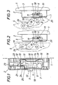
- the locking device shown in FIGS. 1 to 3 essentially consists of a housing 2 which can be fastened to the window or door frame 1 and which has at least one side wall 3 Has receiving slot 4 for a locking pin 6 assigned to the window or door leaf 5.
- This receiving slot 4 extends parallel to the housing 2 supporting St q ckschenkel and is provided with a transverse insertion opening 7, through which the locking pin or tilting 6 when closing the leaf from the.
- Rotary opening position engages in the receiving slot 4.
- the insertion opening 7 of the receiving slot 4 can be closed by a locking slide 8 which carries an operating handle 9 for its handling.
- the locking pin 6 can be held within the receiving slot 4 in two locking positions.
- a locking body 10 is provided, which is mounted transversely to the receiving slot 4 in the housing 2 and two Rastaus recesses 11 for the locking pin 6. 1, two lateral bearing lugs 12, which engage in two mutually opposite grooves 13 running transversely to the receiving slot 4, so that the bearing body 10 pivots on the one hand about the bearing lugs 12 as an axis of rotation and on the other hand transversely along the grooves 13 can be moved to the guide slot 4.
- the latching body 10 is acted upon by a return spring 14, which in the exemplary embodiment is designed as a leaf spring and is located in a guide recess 15 of the insert Housing base 16 supports.
- the locking body 10 is consequently pressed by the return spring 14 against the locking slide 8, on which it rests with a guide web 17 which is provided on a side leg 18 of the locking body 10.
- the locking slide 8 is thus slidably guided parallel to the receiving slot 4 between the housing 2 and the guide web 17, it being possible to move the latching body 10 out of its locking position against the force of the return spring 14 into an unlocking position via the actuating handle 9, because yes Locking slide 8 is supported directly on the guide web 17 of the locking body 10.
- the locking pin 6 engages when the wing 5 is closed through the insertion opening 7 into the receiving slot 4, it is moved after the closing of the insertion opening 7 by the locking slide 8 when opening the wing according to FIG. 2 in its rotational position in the receiving slot 4 because the locking pin 6 is articulated on the wing 5 via a link 19.
- the locking pin 6 strikes an inclined run-up surface 20 of the locking body, so that the locking body 10 is pressed against the force of the return spring 14 into its unlocking position by the locking pin guided in the receiving slot 4 via the ramp surface 20 forming an adjusting wedge is and the locking pin 6 engages in the locking recess 11 for the smaller gap width because the locking body is pressed back into its locking position by the return spring.
- the locking pin 6 is thus held within the receiving slot 4 without play.
- the latching body 10 must be pressed into its unlocking position by hand, which is done via the actuating handle 9 of the locking slide 7. After unlocking the locking pin 6, the sash can be opened until the locking pin 6 strikes the rear boundary wall of the locking recess 11, whereby the gap ventilation position for the larger ventilation gap is reached, in which the locking pin 6 is locked again.
- the wing To open the wing from a night ventilation position, the wing must first be closed by unlocking the locking device before the locking pin 6 can leave the receiving slot 4 through the insertion opening -7 after opening the locking slide 7.
- This closing movement of the wing which is necessary for the locking pin 6 to emerge from the housing 2, represents an additional child safety device.
- the locking position of the locking slide 7 can be locked by a lock 21 be lockable.
- this lock which can only be actuated with a suitable key, has an eccentric pin 22 which engages in an elongated hole 23 of a locking finger 24. This locking finger 24 can be pushed by means of the lock 21 in the closed position of the locking slide 8 in front of a locking stop 25 of the locking slide, so that the locking slide 8 can no longer be withdrawn from its closed position.
- Fig. 3 the night ventilation position for the wing 5 in its tilted position is shown.
- the. Handlebars 19 pivotable against a weight or spring load on the wing so that it independently assumes the desired starting position. For this purpose, it is sufficient to use the dead weight moment and to limit the swivel angle, for example by means of a stop 26.
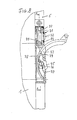
- FIG. 4 shows an embodiment of the locking device according to the invention, in which an elongated housing 30 is pivotably attached to the window or door frame 1 via a stop tab 31.
- a pin 34 is attached to the wing 2 by means of a stop part 32, which in the coupled position engages in the housing 30 via a longitudinal slot 43 and can be locked in this housing in different positions.
- the latching of the pin 34 in the housing can be released by means of a slide 33, and this slide 33 also serves to close an inlet slot 44 for the pin 34 on the housing side.
- FIG. 5 shows an inside view of the housing 30 with for releasably blocking a coupling member 35 accommodated in the housing 30 for different opening positions.
- the housing 30 has an inlet slot 44 for the pin 34 provided on the wing side.
- the pin 34 can enter this slot 44 when the sash is closed and in the process reaches a pin receiving groove 36 of the coupling member 35.
- the inlet slot 44 can be closed by means of the end 45 of the actuating rod 38.
- a slot 43 extends in the longitudinal direction of the housing 30, in which the pin 34 can move when the device is in operation.
- the coupling member 35 is biased in the direction of a double locking bar 41 by means of spring elements 37, which in this example are molded directly onto the plastic coupling member 35.
- the coupling member 35 has locking cams 40 which can engage in the corresponding rectangular toothing 42 of the locking strips 41.
- the two locking strips are spaced apart from one another, and between the two locking strips there is the actuating rod 38 shown in FIG. 6, which is provided with helical teeth 39 and can be actuated via the slide 33 projecting outwards beyond the housing 30.
- This actuating rod 38 which serves at the same time with its end 45 for closing the inlet slot 44 of the housing, makes it possible to raise the coupling member 35, regardless of its instantaneous position, against the force of the springs 37 from the rectangular toothing 42 and thus to decouple it from the locking strips 41.
- the coupling member 35 can be locked in any position along the locking strips 41 and the gap opening width can thus be adjusted according to the tooth steps.
- Fig. 7 shows an embodiment of a locking device according to the invention, in which a housing 50 is fixedly attached to the door or window frame 1 and a holding element 64 is also fixedly arranged on the wing 5.
- a flexible band 51 is arranged in the housing 50 so as to be longitudinally displaceable and exits through a housing slot 63 in the upper end region 66 of the housing 50.
- This elastic band preferably consists of a spring band, or several layered and interconnected spring bands.
- An end stop 52 prevents the band 51 from being pulled out of the housing 50.
- the respective extended position of the band 51 and thus the gap opening width can be set continuously by means of a two-armed locking lever 55, 56.
- This locking lever is pivotally mounted in the housing 50 and presses with its short arm 56 directly against the band 51, while its long arm 55, which runs in the longitudinal direction of the housing, can be actuated via a button 53 which is under the pretensioning force of a spring 54.
- This spring 54 defines the contact pressure via the corresponding lever ratio, by means of which the short arm 56 presses against the band 51 and holds it in place
- an opening 65 is provided, into which a connecting pin 60 which is guided in a longitudinally displaceable manner in the holding element 64 can engage.
- This connecting pin 60 is biased by a spring 59 in the coupling direction.
- the connecting pin 60 can be locked by means of a lock cam 62, the associated lock according to the embodiment according to FIG. 1 being operable by means of a corresponding key and having the same function in each case.
- the wing 5 can be opened or tilted if the key 53 is operated at the same time.
- the button is released, the band 51 is blocked and the gap opening width is thus determined.
- the free end 61 of the spring band 51 is preferably curved, this curved region being a run-up slope for the connecting pin 60 and enabling positive recoupling.
- FIG. 8 is comparable to the embodiment variant according to FIG. 7, but it does not have a spring band in the corresponding housing 70, but rather an extendable link segment 73, which is dashed in the retracted position with solid lines and in the extended position is shown.
- This link segment 73 is part-circular and has over its entire length a locking toothing 78 which cooperates with a locking member 77 having a complementary toothing.
- This locking member 77 is pivotally mounted in the housing 70 and can be actuated via a button 75, which in turn is biased in the locking direction by a spring 76.
- the link segment 73 is provided with a coupling pin 74 extending transversely to the swivel plane.
- This coupling pin 74 engages in a receptacle 79 of a holding element 71 and can be held in this receptacle by means of an adjusting slide 72.
- the adjusting slide 72 can be blocked by means of a locking lock 80, which is comparable to the locking lock shown in FIG. 1 and has a corresponding function.
- This embodiment shown in FIG. 8 is characterized by particular stability with a compact structure and can absorb forces in both the opening and closing directions in the same way.
- a clamping locking according to the variant according to FIG. 7 can also be provided.
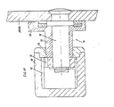
- FIG. 9 shows a front view of a further embodiment variant of the invention, in which a housing 90 is in turn pivotally arranged on the door or window frame 5, while a connecting unit 91 is attached to the wing 5.
- a pivot lever 92 is assigned to this connecting unit 91, by means of which the mutual latching of the housing 90 and the connecting unit 91 is controlled.
- the connecting unit 91 is inserted through an opening 97 at the housing end, and the housing 90 is provided with a longitudinal slot 99 over practically its entire length in order to enable the required relative movement between the housing 90 and the connecting unit 91.
- the housing 90 which is pivotably mounted on an axis 96 via a screw-on plate 100, which is not shown in more detail on the window or door frame 1, has a toothed strip extending over its length on an inner wall 95, which cooperates with a correspondingly toothed locking element 94 of the connecting unit 91.
- This interaction can be seen in detail in FIG. 111.
- FIG. 11 shows, in the form of a sectional view along the line AA in FIG. 10, again the housing 90 with the toothed rack 95.
- a pin 98 of the connecting unit 91 extends through the longitudinal slot 99 in the housing 90, and this pin 98 carries an eccentric sleeve 93 which is rotatable with the pin 98 by means of the pivot lever 92.
- the locking element 94 is attached to the part of the pin 98 lying in the housing 90.
- the locking element 94 By pivoting the lever 92, due to the action of the eccentric sleeve 93, the locking element 94 can be brought into engagement and locked at any point with the toothed strip 95 of the housing 90. In this way, the required gap opening width is determined.
- This embodiment is also characterized by functional reliability, robustness and compactness.
Applications Claiming Priority (2)
| Application Number | Priority Date | Filing Date | Title |
|---|---|---|---|
| AT1152/85 | 1985-04-17 | ||
| AT0115285A AT384649B (de) | 1985-04-17 | 1985-04-17 | Feststellvorrichtung fuer einen fenster- oder tuerfluegel in wenigstens einer spaltlueftungsstellung |
Publications (3)
| Publication Number | Publication Date |
|---|---|
| EP0199270A2 true EP0199270A2 (fr) | 1986-10-29 |
| EP0199270A3 EP0199270A3 (en) | 1988-12-14 |
| EP0199270B1 EP0199270B1 (fr) | 1993-06-30 |
Family
ID=3507741
Family Applications (1)
| Application Number | Title | Priority Date | Filing Date |
|---|---|---|---|
| EP86105215A Expired - Lifetime EP0199270B1 (fr) | 1985-04-17 | 1986-04-16 | Dispositif pour maintenir une porte ou une fenêtre entrouverte dans au moins une position |
Country Status (3)
| Country | Link |
|---|---|
| EP (1) | EP0199270B1 (fr) |
| AT (2) | AT384649B (fr) |
| DE (1) | DE3688626D1 (fr) |
Cited By (4)
| Publication number | Priority date | Publication date | Assignee | Title |
|---|---|---|---|---|
| EP0208304A2 (fr) * | 1985-07-08 | 1987-01-14 | Mayer & Co. | Dispositif pour maintenir une porte ou une fenêtre en position ouverte |
| EP0262347A2 (fr) * | 1986-09-11 | 1988-04-06 | Gretsch Unitas GmbH Baubeschläge | Dispositif de maintien en position ouverte d'une porte, d'une fenêtre etc. au moins pivotante |
| GB2287748A (en) * | 1994-03-18 | 1995-09-27 | Winkhaus Fa August | Lockable window or door stay |
| CN114096727A (zh) * | 2019-07-02 | 2022-02-25 | 马科技术有限责任公司 | 用于窗、门等的具有加强壳体的锁扣件 |
Families Citing this family (1)
| Publication number | Priority date | Publication date | Assignee | Title |
|---|---|---|---|---|
| NO172756C (no) * | 1991-02-26 | 1993-09-01 | Grorud Jernvarefab As | Anordning ved stoppermekanisme for vippevindu |
Citations (12)
| Publication number | Priority date | Publication date | Assignee | Title |
|---|---|---|---|---|
| DE313226C (fr) * | ||||
| CH102218A (de) * | 1922-11-04 | 1923-11-16 | Egger Hermann | Einrichtung zum Feststellen von Fenstern. |
| US1726850A (en) * | 1928-02-28 | 1929-09-03 | C E Stanton | Window fastener |
| US1992886A (en) * | 1931-04-23 | 1935-02-26 | Ainsworth Mfg Company | Control means for windshields |
| US2699352A (en) * | 1952-05-26 | 1955-01-11 | James S Matthew | Door holding device |
| DE1075006B (fr) * | 1960-02-04 | |||
| FR1362530A (fr) * | 1963-04-03 | 1964-06-05 | Ferco | Compas d'arrêt et de blocage pour fenêtres |
| DE1654735A1 (de) * | 1967-08-29 | 1971-03-25 | Simon Fa Karl | Vorrichtung zur Daempfung der Bewegung eines schwenkbaren Moebelteiles |
| DE2436038A1 (de) * | 1974-07-26 | 1976-02-05 | Braun Ag | Vorrichtung zum arretieren einer abdeckhaube fuer rundfunk- und phonogeraete |
| GB1428960A (en) * | 1972-12-23 | 1976-03-24 | Automatic Pressings Ltd | Restrictor stays primarily for pivoted window structures |
| AT370198B (de) * | 1981-02-18 | 1982-07-15 | Schmidt Josef | Vorrichtung zur halterung eines fensterfluegels |
| AT368594B (de) * | 1976-12-07 | 1982-10-25 | Mayer & Co Riegel Beschlag | Vorrichtung zur loesbaren drehbegrenzung von schwingfluegelfenstern od.dgl |
Family Cites Families (2)
| Publication number | Priority date | Publication date | Assignee | Title |
|---|---|---|---|---|
| DE1584117A1 (de) * | 1965-01-27 | 1969-03-13 | Jaeger Kg Frank | Fluegelfeststeller fuer Fenster,Tueren od. dgl.,insbesondere fuer Kipp-Schwenkfluegel |
| DE3008774A1 (de) * | 1980-03-07 | 1981-09-24 | Siegenia-Frank Kg, 5900 Siegen | Feststellvorrichtung fuer fluegel von fenstern, tueren o.dgl. in wenigstens einer spaltlueftungsstellung |
-
1985
- 1985-04-17 AT AT0115285A patent/AT384649B/de not_active IP Right Cessation
-
1986
- 1986-04-16 DE DE8686105215T patent/DE3688626D1/de not_active Expired - Fee Related
- 1986-04-16 AT AT86105215T patent/ATE91170T1/de not_active IP Right Cessation
- 1986-04-16 EP EP86105215A patent/EP0199270B1/fr not_active Expired - Lifetime
Patent Citations (12)
| Publication number | Priority date | Publication date | Assignee | Title |
|---|---|---|---|---|
| DE313226C (fr) * | ||||
| DE1075006B (fr) * | 1960-02-04 | |||
| CH102218A (de) * | 1922-11-04 | 1923-11-16 | Egger Hermann | Einrichtung zum Feststellen von Fenstern. |
| US1726850A (en) * | 1928-02-28 | 1929-09-03 | C E Stanton | Window fastener |
| US1992886A (en) * | 1931-04-23 | 1935-02-26 | Ainsworth Mfg Company | Control means for windshields |
| US2699352A (en) * | 1952-05-26 | 1955-01-11 | James S Matthew | Door holding device |
| FR1362530A (fr) * | 1963-04-03 | 1964-06-05 | Ferco | Compas d'arrêt et de blocage pour fenêtres |
| DE1654735A1 (de) * | 1967-08-29 | 1971-03-25 | Simon Fa Karl | Vorrichtung zur Daempfung der Bewegung eines schwenkbaren Moebelteiles |
| GB1428960A (en) * | 1972-12-23 | 1976-03-24 | Automatic Pressings Ltd | Restrictor stays primarily for pivoted window structures |
| DE2436038A1 (de) * | 1974-07-26 | 1976-02-05 | Braun Ag | Vorrichtung zum arretieren einer abdeckhaube fuer rundfunk- und phonogeraete |
| AT368594B (de) * | 1976-12-07 | 1982-10-25 | Mayer & Co Riegel Beschlag | Vorrichtung zur loesbaren drehbegrenzung von schwingfluegelfenstern od.dgl |
| AT370198B (de) * | 1981-02-18 | 1982-07-15 | Schmidt Josef | Vorrichtung zur halterung eines fensterfluegels |
Cited By (8)
| Publication number | Priority date | Publication date | Assignee | Title |
|---|---|---|---|---|
| EP0208304A2 (fr) * | 1985-07-08 | 1987-01-14 | Mayer & Co. | Dispositif pour maintenir une porte ou une fenêtre en position ouverte |
| EP0208304A3 (en) * | 1985-07-08 | 1988-11-17 | Mayer & Co. | Device for keeping a door or window open |
| EP0262347A2 (fr) * | 1986-09-11 | 1988-04-06 | Gretsch Unitas GmbH Baubeschläge | Dispositif de maintien en position ouverte d'une porte, d'une fenêtre etc. au moins pivotante |
| EP0262347A3 (en) * | 1986-09-11 | 1988-10-19 | Gretsch Unitas Gmbh Baubeschlage | Device for holding a partially pivoting door or window in an open position |
| GB2287748A (en) * | 1994-03-18 | 1995-09-27 | Winkhaus Fa August | Lockable window or door stay |
| GB2287748B (en) * | 1994-03-18 | 1998-04-08 | Winkhaus Fa August | Apparatus for setting a casement in a vent position on a frame |
| CN114096727A (zh) * | 2019-07-02 | 2022-02-25 | 马科技术有限责任公司 | 用于窗、门等的具有加强壳体的锁扣件 |
| CN114096727B (zh) * | 2019-07-02 | 2024-03-19 | 马科技术有限责任公司 | 用于窗、门等的具有加强壳体的锁扣件 |
Also Published As
| Publication number | Publication date |
|---|---|
| ATE91170T1 (de) | 1993-07-15 |
| AT384649B (de) | 1987-12-10 |
| ATA115285A (de) | 1987-05-15 |
| EP0199270A3 (en) | 1988-12-14 |
| DE3688626D1 (de) | 1993-08-05 |
| EP0199270B1 (fr) | 1993-06-30 |
Similar Documents
| Publication | Publication Date | Title |
|---|---|---|
| DE2732654C3 (de) | Gelenkbeschlag für Leiteiteile | |
| EP1711672B1 (fr) | Charniere a monter dans une ouverture | |
| EP3702562B1 (fr) | Ferrure de fixation ainsi qu'agencement de ferrure et agencement de cadre et de battant | |
| DE202006014041U1 (de) | Klapp-Hebelverschluss | |
| DE3624237A1 (de) | Scharnierband mit leicht loesbarer befestigung des moebelseitigen abdeckbuegels am moebelteil | |
| DE2504420A1 (de) | Treibstangenverschluss, insbesondere fuer fluegel von fenstern, tueren oder dergleichen | |
| EP2733286B1 (fr) | Fermeture à levier pivotant ayant une faible profondeur d'intégration | |
| EP2951374B1 (fr) | Pièce coulissante servant à guider une partie de meuble dans un sens de guidage sur une glissière et ferrure de meuble | |
| EP0169315B1 (fr) | Elément de fixation de ski en particulier mâchoire avant | |
| EP0199270A2 (fr) | Dispositif pour maintenir une porte ou une fenêtre entrouverte dans au moins une position | |
| DE2813311C2 (fr) | ||
| DE3429699C2 (de) | Fehlbedienungssperre für Treibstangenbeschläge | |
| DE3004854C2 (de) | Feststellvorrichtung für Flügel von Fenstern, Türen o.dgl. in wenigstens einer Spaltlüftungsstellung | |
| EP3183408B1 (fr) | Élément de commande pour système de ferrure | |
| EP0247281B1 (fr) | Dispositif de fermeture pour empêcher l'ouverture non autorisée de battants de portes, fenêtres ou similaires | |
| DE2211523B2 (de) | Schließstück für Metall- oder Kunststoff-Fenster oder -Türen | |
| EP1746235A2 (fr) | Ensemble de ferrure | |
| EP0828047B1 (fr) | Serrure à pêne demi-tour | |
| EP2735675B1 (fr) | Dispositif de fermeture pour portes doté d'une plaque de porte asymétrique | |
| CH620734A5 (en) | Automatic roller-shutter safety device | |
| DE2507910B2 (de) | Fehlbedienungssicherung für das Betätigungsgestänge eines Dreh-Kipp-Fensters | |
| DE3215452A1 (de) | Eckumlenkung fuer treibstangenbeschlaege von fenstern, tueren od. dgl. | |
| DE3041221C2 (de) | Verriegelungsbeschlag an einem Kipp-Schiebeflügel, vorzugsweise Hebe-Kipp-Schiebeflügel, von Fenstern, Türen od.dgl. | |
| DE8123266U1 (de) | Eckumlenkung fuer treibstangenbeschlaege von fenstern, tueren o.dgl. | |
| DE2729394A1 (de) | Verriegelungseinrichtung fuer fenster, tueren o.dgl. |
Legal Events
| Date | Code | Title | Description |
|---|---|---|---|
| PUAI | Public reference made under article 153(3) epc to a published international application that has entered the european phase |
Free format text: ORIGINAL CODE: 0009012 |
|
| AK | Designated contracting states |
Kind code of ref document: A2 Designated state(s): AT DE GB |
|
| RHK1 | Main classification (correction) |
Ipc: E05C 17/28 |
|
| PUAL | Search report despatched |
Free format text: ORIGINAL CODE: 0009013 |
|
| AK | Designated contracting states |
Kind code of ref document: A3 Designated state(s): AT DE GB |
|
| 17P | Request for examination filed |
Effective date: 19890201 |
|
| 17Q | First examination report despatched |
Effective date: 19890927 |
|
| GRAA | (expected) grant |
Free format text: ORIGINAL CODE: 0009210 |
|
| AK | Designated contracting states |
Kind code of ref document: B1 Designated state(s): AT DE GB |
|
| REF | Corresponds to: |
Ref document number: 91170 Country of ref document: AT Date of ref document: 19930715 Kind code of ref document: T |
|
| REF | Corresponds to: |
Ref document number: 3688626 Country of ref document: DE Date of ref document: 19930805 |
|
| GBT | Gb: translation of ep patent filed (gb section 77(6)(a)/1977) |
Effective date: 19930722 |
|
| PLBE | No opposition filed within time limit |
Free format text: ORIGINAL CODE: 0009261 |
|
| STAA | Information on the status of an ep patent application or granted ep patent |
Free format text: STATUS: NO OPPOSITION FILED WITHIN TIME LIMIT |
|
| 26N | No opposition filed | ||
| PGFP | Annual fee paid to national office [announced via postgrant information from national office to epo] |
Ref country code: GB Payment date: 19950329 Year of fee payment: 10 |
|
| PGFP | Annual fee paid to national office [announced via postgrant information from national office to epo] |
Ref country code: AT Payment date: 19950420 Year of fee payment: 10 |
|
| PGFP | Annual fee paid to national office [announced via postgrant information from national office to epo] |
Ref country code: DE Payment date: 19950613 Year of fee payment: 10 |
|
| PG25 | Lapsed in a contracting state [announced via postgrant information from national office to epo] |
Ref country code: GB Effective date: 19960416 Ref country code: AT Effective date: 19960416 |
|
| GBPC | Gb: european patent ceased through non-payment of renewal fee |
Effective date: 19960416 |
|
| PG25 | Lapsed in a contracting state [announced via postgrant information from national office to epo] |
Ref country code: DE Effective date: 19970101 |