EP0199270A2 - Device for keeping a door or window at least ajar - Google Patents
Device for keeping a door or window at least ajar Download PDFInfo
- Publication number
- EP0199270A2 EP0199270A2 EP86105215A EP86105215A EP0199270A2 EP 0199270 A2 EP0199270 A2 EP 0199270A2 EP 86105215 A EP86105215 A EP 86105215A EP 86105215 A EP86105215 A EP 86105215A EP 0199270 A2 EP0199270 A2 EP 0199270A2
- Authority
- EP
- European Patent Office
- Prior art keywords
- locking
- housing
- pin
- locking device
- window
- Prior art date
- Legal status (The legal status is an assumption and is not a legal conclusion. Google has not performed a legal analysis and makes no representation as to the accuracy of the status listed.)
- Granted
Links
Images


Classifications
-
- E—FIXED CONSTRUCTIONS
- E05—LOCKS; KEYS; WINDOW OR DOOR FITTINGS; SAFES
- E05C—BOLTS OR FASTENING DEVICES FOR WINGS, SPECIALLY FOR DOORS OR WINDOWS
- E05C17/00—Devices for holding wings open; Devices for limiting opening of wings or for holding wings open by a movable member extending between frame and wing; Braking devices, stops or buffers, combined therewith
- E05C17/02—Devices for holding wings open; Devices for limiting opening of wings or for holding wings open by a movable member extending between frame and wing; Braking devices, stops or buffers, combined therewith by mechanical means
- E05C17/04—Devices for holding wings open; Devices for limiting opening of wings or for holding wings open by a movable member extending between frame and wing; Braking devices, stops or buffers, combined therewith by mechanical means with a movable bar or equivalent member extending between frame and wing
- E05C17/12—Devices for holding wings open; Devices for limiting opening of wings or for holding wings open by a movable member extending between frame and wing; Braking devices, stops or buffers, combined therewith by mechanical means with a movable bar or equivalent member extending between frame and wing consisting of a single rod
- E05C17/16—Devices for holding wings open; Devices for limiting opening of wings or for holding wings open by a movable member extending between frame and wing; Braking devices, stops or buffers, combined therewith by mechanical means with a movable bar or equivalent member extending between frame and wing consisting of a single rod pivoted only at one end and having an elongated slot
-
- E—FIXED CONSTRUCTIONS
- E05—LOCKS; KEYS; WINDOW OR DOOR FITTINGS; SAFES
- E05C—BOLTS OR FASTENING DEVICES FOR WINGS, SPECIALLY FOR DOORS OR WINDOWS
- E05C17/00—Devices for holding wings open; Devices for limiting opening of wings or for holding wings open by a movable member extending between frame and wing; Braking devices, stops or buffers, combined therewith
- E05C17/02—Devices for holding wings open; Devices for limiting opening of wings or for holding wings open by a movable member extending between frame and wing; Braking devices, stops or buffers, combined therewith by mechanical means
- E05C17/04—Devices for holding wings open; Devices for limiting opening of wings or for holding wings open by a movable member extending between frame and wing; Braking devices, stops or buffers, combined therewith by mechanical means with a movable bar or equivalent member extending between frame and wing
- E05C17/12—Devices for holding wings open; Devices for limiting opening of wings or for holding wings open by a movable member extending between frame and wing; Braking devices, stops or buffers, combined therewith by mechanical means with a movable bar or equivalent member extending between frame and wing consisting of a single rod
- E05C17/24—Devices for holding wings open; Devices for limiting opening of wings or for holding wings open by a movable member extending between frame and wing; Braking devices, stops or buffers, combined therewith by mechanical means with a movable bar or equivalent member extending between frame and wing consisting of a single rod pivoted at one end, and with the other end running along a guide member
- E05C17/28—Devices for holding wings open; Devices for limiting opening of wings or for holding wings open by a movable member extending between frame and wing; Braking devices, stops or buffers, combined therewith by mechanical means with a movable bar or equivalent member extending between frame and wing consisting of a single rod pivoted at one end, and with the other end running along a guide member with braking, clamping or securing means at the connection to the guide member
-
- E—FIXED CONSTRUCTIONS
- E05—LOCKS; KEYS; WINDOW OR DOOR FITTINGS; SAFES
- E05C—BOLTS OR FASTENING DEVICES FOR WINGS, SPECIALLY FOR DOORS OR WINDOWS
- E05C17/00—Devices for holding wings open; Devices for limiting opening of wings or for holding wings open by a movable member extending between frame and wing; Braking devices, stops or buffers, combined therewith
- E05C17/02—Devices for holding wings open; Devices for limiting opening of wings or for holding wings open by a movable member extending between frame and wing; Braking devices, stops or buffers, combined therewith by mechanical means
- E05C17/04—Devices for holding wings open; Devices for limiting opening of wings or for holding wings open by a movable member extending between frame and wing; Braking devices, stops or buffers, combined therewith by mechanical means with a movable bar or equivalent member extending between frame and wing
- E05C17/36—Devices for holding wings open; Devices for limiting opening of wings or for holding wings open by a movable member extending between frame and wing; Braking devices, stops or buffers, combined therewith by mechanical means with a movable bar or equivalent member extending between frame and wing comprising a flexible member, e.g. chains
-
- E—FIXED CONSTRUCTIONS
- E05—LOCKS; KEYS; WINDOW OR DOOR FITTINGS; SAFES
- E05C—BOLTS OR FASTENING DEVICES FOR WINGS, SPECIALLY FOR DOORS OR WINDOWS
- E05C17/00—Devices for holding wings open; Devices for limiting opening of wings or for holding wings open by a movable member extending between frame and wing; Braking devices, stops or buffers, combined therewith
- E05C17/02—Devices for holding wings open; Devices for limiting opening of wings or for holding wings open by a movable member extending between frame and wing; Braking devices, stops or buffers, combined therewith by mechanical means
- E05C17/38—Devices for holding wings open; Devices for limiting opening of wings or for holding wings open by a movable member extending between frame and wing; Braking devices, stops or buffers, combined therewith by mechanical means with a curved rail rigid with the frame for engagement with means on the wing, or vice versa
Definitions
- the invention relates to a locking device for a window or door leaf in at least one night ventilation position, consisting of a housing which can be fastened to the window or door frame and in which a coupling member is provided for releasable connection to a holding element which can be attached to the leaf.
- the receiving slot of the housing which can be fastened to the window or door frame runs normal to the level of the floor, so that the locking pin screwed onto the wing engages in the receiving slot when the wing is closed from its rotational opening position. Due to the locking body, which is slidably mounted in the housing in the longitudinal direction of the support leg and has two locking recesses for the locking pin, the locking pin can be held within the receiving slot in two locking positions, which correspond to two gap ventilation positions of the wing.
- the edge of the receiving slot facing the tilt axis runs along a circular cylinder concentric with the tilt axis.
- a disadvantage of this known locking device is that due to the orientation of the receiving slot perpendicular to the floor level, the housing must have a depth that is greater than the desired width for the ventilation gap, which in particular with larger ventilation gaps causes a disturbing protrusion of the housing into the interior of the room.
- the locking body can only be moved across the locking pin into the locking position transversely to the receiving slot when the locking pin actually assumes the intended position, so that the handling of the locking device is difficult.
- the locking device is not childproof, because the locking body for unlocking the locking device only has to be withdrawn from the locking position into the unlocking position via an actuating handle and is held in this unlocking position by means of a locking device. Also, due to the inevitably necessary over-dimensioning of the locking recesses, a disturbing rattling of the window or door wing in its night ventilation position cannot be avoided.
- the invention is therefore based on the object to avoid these deficiencies and to improve a locking device of the type described in such a way that not only simple, child-safe handling, but also a flat design for comparatively large ventilation gaps can be ensured, namely under a rattle-free Holding the window or door leaf in both the tilt and the turn position.
- the invention solves this problem according to a first embodiment in that the receiving slot runs at least substantially parallel to the stick leg supporting the housing and has an insertion opening which can be closed by a locking slide for the locking pin articulated by means of a link on the wing and that the locking body counteracts from its locking position the force of a return spring can be shifted into the unlocking position.
- the receiving slot By arranging the receiving slot parallel to the stick leg supporting the housing, it is first achieved that the length of the receiving slot and thus the width of the ventilation gap has no influence on the depth of the housing, so that very flat housings can also be used for comparatively large gap widths, which in particular is a significant advantage when retrofitting such locking devices.
- This parallel to the stick leg course of the receiving slot requires that the locking pin must be attached to the wing by means of a handlebar, in order to ensure a corresponding wing adjustment by means of a displacement of the locking pin parallel to the stick plane, which is caused both by pivoting about the axis of rotation and about the tilt axis of the Wing can be done. The across to the closing or.
- Opening movement of the wing extending receiving slot also allows the locking body to be held in its locking position by a return spring, so that to unlock the locking device of the locking body against the force of the return spring in its unlocking position and at the same time the wing must be opened, which the desired child safety in handling. If the window or door sash is not held in a gap ventilation position by the locking device, the sash can enter the insertion opening of the receiving slot unhindered by the latching body, which is held in its locking position by the return spring, during opening and closing, because this insertion opening is forced must run across the receiving slot.
- the locking pin is moved along the receiving slot and does not emerge from the insertion opening, the insertion opening is closed by a locking slide.
- the locking pin is consequently ge when the insertion opening is closed in the receiving slot catch and can be held in the desired slot ventilation position of the wing by the locking body in the receiving slot.
- the locking body in the area of the receiving slot can have an inclined run-up surface for the locking pin, so that when the wing is opened after the insertion opening is closed, the inside of the receiving slot guided locking pin presses the locking body over the inclined ramp surface against the force of the return spring in its unlocked position and automatically engages in the following locking recess.
- the latching body must be brought into its unlocked position by hand against the force of the return spring before the sash can be opened further. No run-up surfaces are desired in the area of the recesses so that the sash cannot leave the set night ventilation position due to a corresponding load.
- the locking body must be able to be moved into its unlocking position transversely to the receiving slot.
- a pure displacement movement of the locking body harbors the risk of the locking body tilting in its sliding guide, in particular when the locking body is loaded on one side, as occurs when the locking body is adjusted via the locking pin acting on the ramp surface.
- the latching body can be positioned in two opposite bearing lugs via two lateral bearing lugs forming an axis of rotation. across. to the receiving slot extending grooves of the housing. These two grooves form a sliding guide for the bearing lugs, so that the locking body can be moved over the bearing lugs in the grooves and can also be rotated around the bearing lugs. Depending on the load case, the locking body is therefore moved or pivoted, which ensures the correct adjustment of the locking body.
- the locking slide provided with an actuating handle can be displaceably held transversely to the receiving slot in the housing and supported on a guide web of the locking body.
- the locking slide can be moved via the actuating handle to close the insertion opening on the one hand along the guide web and, on the other hand, displaced to unlock the locking body transversely to the guide web, because the locking slide is supported on the guide web of the locking body and adjusts the locking body transversely to the receiving slot via this guide web.
- This construction not only offers advantageous handling, but also simple guidance for the locking slide between the housing and the guide web of the locking body.
- the closed position of the locking slide can be locked by means of a lock. After the locking slide has been locked, it is only possible to adjust the sash between its closed position and one of the intended night ventilation positions.
- the handlebar carrying the locking pin can be pivoted out against a weight or spring load on the wing, so that the handlebar automatically returns to its initial position after its release.
- the object is achieved in that the housing is fastened to the window or door frame and has an inlet slot, which can be closed by means of a slide, for a connecting pin forming the wing-side holding element, that in the closed position of the wing, a pin receiving groove of the in Longitudinal housing movable coupling member is aligned with the inlet slot that the coupling member is resiliently mounted in the transverse direction of the housing and is provided on the side facing away from the sprung side with locking cams which cooperate with a corresponding locking bar which extends essentially over the length of the housing, and that the slide is provided with an actuating rod which extends over the entire length of the locking bar, for example with a helical tooth, for decoupling the coupling member and locking bar independently of the position.
- a third variant of the solution according to the invention is characterized in that the coupling member consists of an elastic band which is longitudinally displaceably guided in the housing, which can be extended via a housing slot and can be fixed in different extension positions, in that for the fixing of the band in the housing, one is fastened by a pretensioned one
- Spring-loaded button releasable locking device is provided that in the wing-side holding element a spring pin is arranged connecting pin which is intended to engage in an opening provided in the region of the free end of the elastic band, and that only when the wing is closed, the connecting pin an actuator can be released from the coupling position with the elastic band.
- Embodiment which ensures a continuous adjustment of the gap opening width, is characterized by particular simplicity and flat design.
- the coupling member consists of a preferably segmentally curved, guided in the housing and extendable via a housing slot link segment, which is provided at its outer end with a transverse to the pivoting coupling pin, which is in a receptacle of the wing-side holding element with the wing closed can be fixed by means of an adjusting slide, the link segment being able to be fixed in different extension positions by means of a spring-loaded spring element which is pivotably mounted in the housing and can be actuated by means of a button.
- This device is particularly compact, is also suitable for absorbing particularly large forces and is extremely reliable.
- a fifth variant for solving the problem is that the housing is elongated, pivotally attached to the window or door frame and is provided at the free end with an opening for receiving a wing-side holding element and the coupling member, and that over the Opening insertable into the housing and displaceable in the longitudinal direction of the housing can be clamped in the housing by means of an eccentric arrangement which can be actuated via a pivoting lever.
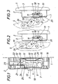
- the locking device shown in FIGS. 1 to 3 essentially consists of a housing 2 which can be fastened to the window or door frame 1 and which has at least one side wall 3 Has receiving slot 4 for a locking pin 6 assigned to the window or door leaf 5.
- This receiving slot 4 extends parallel to the housing 2 supporting St q ckschenkel and is provided with a transverse insertion opening 7, through which the locking pin or tilting 6 when closing the leaf from the.
- Rotary opening position engages in the receiving slot 4.
- the insertion opening 7 of the receiving slot 4 can be closed by a locking slide 8 which carries an operating handle 9 for its handling.
- the locking pin 6 can be held within the receiving slot 4 in two locking positions.
- a locking body 10 is provided, which is mounted transversely to the receiving slot 4 in the housing 2 and two Rastaus recesses 11 for the locking pin 6. 1, two lateral bearing lugs 12, which engage in two mutually opposite grooves 13 running transversely to the receiving slot 4, so that the bearing body 10 pivots on the one hand about the bearing lugs 12 as an axis of rotation and on the other hand transversely along the grooves 13 can be moved to the guide slot 4.
- the latching body 10 is acted upon by a return spring 14, which in the exemplary embodiment is designed as a leaf spring and is located in a guide recess 15 of the insert Housing base 16 supports.
- the locking body 10 is consequently pressed by the return spring 14 against the locking slide 8, on which it rests with a guide web 17 which is provided on a side leg 18 of the locking body 10.
- the locking slide 8 is thus slidably guided parallel to the receiving slot 4 between the housing 2 and the guide web 17, it being possible to move the latching body 10 out of its locking position against the force of the return spring 14 into an unlocking position via the actuating handle 9, because yes Locking slide 8 is supported directly on the guide web 17 of the locking body 10.
- the locking pin 6 engages when the wing 5 is closed through the insertion opening 7 into the receiving slot 4, it is moved after the closing of the insertion opening 7 by the locking slide 8 when opening the wing according to FIG. 2 in its rotational position in the receiving slot 4 because the locking pin 6 is articulated on the wing 5 via a link 19.
- the locking pin 6 strikes an inclined run-up surface 20 of the locking body, so that the locking body 10 is pressed against the force of the return spring 14 into its unlocking position by the locking pin guided in the receiving slot 4 via the ramp surface 20 forming an adjusting wedge is and the locking pin 6 engages in the locking recess 11 for the smaller gap width because the locking body is pressed back into its locking position by the return spring.
- the locking pin 6 is thus held within the receiving slot 4 without play.
- the latching body 10 must be pressed into its unlocking position by hand, which is done via the actuating handle 9 of the locking slide 7. After unlocking the locking pin 6, the sash can be opened until the locking pin 6 strikes the rear boundary wall of the locking recess 11, whereby the gap ventilation position for the larger ventilation gap is reached, in which the locking pin 6 is locked again.
- the wing To open the wing from a night ventilation position, the wing must first be closed by unlocking the locking device before the locking pin 6 can leave the receiving slot 4 through the insertion opening -7 after opening the locking slide 7.
- This closing movement of the wing which is necessary for the locking pin 6 to emerge from the housing 2, represents an additional child safety device.
- the locking position of the locking slide 7 can be locked by a lock 21 be lockable.
- this lock which can only be actuated with a suitable key, has an eccentric pin 22 which engages in an elongated hole 23 of a locking finger 24. This locking finger 24 can be pushed by means of the lock 21 in the closed position of the locking slide 8 in front of a locking stop 25 of the locking slide, so that the locking slide 8 can no longer be withdrawn from its closed position.
- Fig. 3 the night ventilation position for the wing 5 in its tilted position is shown.
- the. Handlebars 19 pivotable against a weight or spring load on the wing so that it independently assumes the desired starting position. For this purpose, it is sufficient to use the dead weight moment and to limit the swivel angle, for example by means of a stop 26.
- FIG. 4 shows an embodiment of the locking device according to the invention, in which an elongated housing 30 is pivotably attached to the window or door frame 1 via a stop tab 31.
- a pin 34 is attached to the wing 2 by means of a stop part 32, which in the coupled position engages in the housing 30 via a longitudinal slot 43 and can be locked in this housing in different positions.
- the latching of the pin 34 in the housing can be released by means of a slide 33, and this slide 33 also serves to close an inlet slot 44 for the pin 34 on the housing side.
- FIG. 5 shows an inside view of the housing 30 with for releasably blocking a coupling member 35 accommodated in the housing 30 for different opening positions.
- the housing 30 has an inlet slot 44 for the pin 34 provided on the wing side.
- the pin 34 can enter this slot 44 when the sash is closed and in the process reaches a pin receiving groove 36 of the coupling member 35.
- the inlet slot 44 can be closed by means of the end 45 of the actuating rod 38.
- a slot 43 extends in the longitudinal direction of the housing 30, in which the pin 34 can move when the device is in operation.
- the coupling member 35 is biased in the direction of a double locking bar 41 by means of spring elements 37, which in this example are molded directly onto the plastic coupling member 35.
- the coupling member 35 has locking cams 40 which can engage in the corresponding rectangular toothing 42 of the locking strips 41.
- the two locking strips are spaced apart from one another, and between the two locking strips there is the actuating rod 38 shown in FIG. 6, which is provided with helical teeth 39 and can be actuated via the slide 33 projecting outwards beyond the housing 30.
- This actuating rod 38 which serves at the same time with its end 45 for closing the inlet slot 44 of the housing, makes it possible to raise the coupling member 35, regardless of its instantaneous position, against the force of the springs 37 from the rectangular toothing 42 and thus to decouple it from the locking strips 41.
- the coupling member 35 can be locked in any position along the locking strips 41 and the gap opening width can thus be adjusted according to the tooth steps.
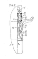
- Fig. 7 shows an embodiment of a locking device according to the invention, in which a housing 50 is fixedly attached to the door or window frame 1 and a holding element 64 is also fixedly arranged on the wing 5.
- a flexible band 51 is arranged in the housing 50 so as to be longitudinally displaceable and exits through a housing slot 63 in the upper end region 66 of the housing 50.
- This elastic band preferably consists of a spring band, or several layered and interconnected spring bands.
- An end stop 52 prevents the band 51 from being pulled out of the housing 50.
- the respective extended position of the band 51 and thus the gap opening width can be set continuously by means of a two-armed locking lever 55, 56.
- This locking lever is pivotally mounted in the housing 50 and presses with its short arm 56 directly against the band 51, while its long arm 55, which runs in the longitudinal direction of the housing, can be actuated via a button 53 which is under the pretensioning force of a spring 54.
- This spring 54 defines the contact pressure via the corresponding lever ratio, by means of which the short arm 56 presses against the band 51 and holds it in place
- an opening 65 is provided, into which a connecting pin 60 which is guided in a longitudinally displaceable manner in the holding element 64 can engage.
- This connecting pin 60 is biased by a spring 59 in the coupling direction.
- the connecting pin 60 can be locked by means of a lock cam 62, the associated lock according to the embodiment according to FIG. 1 being operable by means of a corresponding key and having the same function in each case.
- the wing 5 can be opened or tilted if the key 53 is operated at the same time.
- the button is released, the band 51 is blocked and the gap opening width is thus determined.
- the free end 61 of the spring band 51 is preferably curved, this curved region being a run-up slope for the connecting pin 60 and enabling positive recoupling.
- FIG. 8 is comparable to the embodiment variant according to FIG. 7, but it does not have a spring band in the corresponding housing 70, but rather an extendable link segment 73, which is dashed in the retracted position with solid lines and in the extended position is shown.
- This link segment 73 is part-circular and has over its entire length a locking toothing 78 which cooperates with a locking member 77 having a complementary toothing.
- This locking member 77 is pivotally mounted in the housing 70 and can be actuated via a button 75, which in turn is biased in the locking direction by a spring 76.
- the link segment 73 is provided with a coupling pin 74 extending transversely to the swivel plane.
- This coupling pin 74 engages in a receptacle 79 of a holding element 71 and can be held in this receptacle by means of an adjusting slide 72.
- the adjusting slide 72 can be blocked by means of a locking lock 80, which is comparable to the locking lock shown in FIG. 1 and has a corresponding function.
- This embodiment shown in FIG. 8 is characterized by particular stability with a compact structure and can absorb forces in both the opening and closing directions in the same way.
- a clamping locking according to the variant according to FIG. 7 can also be provided.
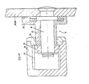
- FIG. 9 shows a front view of a further embodiment variant of the invention, in which a housing 90 is in turn pivotally arranged on the door or window frame 5, while a connecting unit 91 is attached to the wing 5.
- a pivot lever 92 is assigned to this connecting unit 91, by means of which the mutual latching of the housing 90 and the connecting unit 91 is controlled.
- the connecting unit 91 is inserted through an opening 97 at the housing end, and the housing 90 is provided with a longitudinal slot 99 over practically its entire length in order to enable the required relative movement between the housing 90 and the connecting unit 91.
- the housing 90 which is pivotably mounted on an axis 96 via a screw-on plate 100, which is not shown in more detail on the window or door frame 1, has a toothed strip extending over its length on an inner wall 95, which cooperates with a correspondingly toothed locking element 94 of the connecting unit 91.
- This interaction can be seen in detail in FIG. 111.
- FIG. 11 shows, in the form of a sectional view along the line AA in FIG. 10, again the housing 90 with the toothed rack 95.
- a pin 98 of the connecting unit 91 extends through the longitudinal slot 99 in the housing 90, and this pin 98 carries an eccentric sleeve 93 which is rotatable with the pin 98 by means of the pivot lever 92.
- the locking element 94 is attached to the part of the pin 98 lying in the housing 90.
- the locking element 94 By pivoting the lever 92, due to the action of the eccentric sleeve 93, the locking element 94 can be brought into engagement and locked at any point with the toothed strip 95 of the housing 90. In this way, the required gap opening width is determined.
- This embodiment is also characterized by functional reliability, robustness and compactness.
Abstract
Description
Die Erfindung betrifft eine Feststellvorrichtung für einen Fenster-oder Türflügel in wenigstens einer Spaltlüftungsstellung, bestehend aus einem am Fenster-oder Türstock befestigbaren Gehäuse, in dem ein Kupplungsorgan zur lösbaren Verbindung mit einem am Flügel anschlagbaren Halteelement vorgesehen ist.The invention relates to a locking device for a window or door leaf in at least one night ventilation position, consisting of a housing which can be fastened to the window or door frame and in which a coupling member is provided for releasable connection to a holding element which can be attached to the leaf.
Bei einer bekannten Feststellvorrichtung dieser Art (DE-GM 1 922 908) verläuft der Aufnahmeschlitz des am Fenster-oder Türstock befestigbaren Gehäuses normal zur Stockebene, so daß der am Flügel angeschraubte Raststift beim Schließen des Flügels aus seiner Drehöffnungsstellung in den Aufnahmeschlitz eingreift. Durch den Rastkörper, der in Längsrichtung des das Gehäuse tragenden Stockschenkels verschiebbar im Gehäuse gelagert ist und zwei Rastausnehmungen für den Raststift aufweist, kann der Raststift innerhalb des Aufnahmeschlitzes in zwei Raststellungen festgehalten werden, denen zwei Spaltlüftungsstellungen des Flügels entsprechen. Um den Flügel nicht nur um seine Drehachse, sondern auch um seine Kippachse in eine Spaltlüftungsstellung öffnen zu können, verläuft der der Kippachse zugekehrte Rand des Aufnahmeschlitzes entlang eines zur Kippachse konzentrischen Kreiszylinders. Nachteilig bei dieser bekannten Feststellvonichtung ist, daß zufolge der Ausrichtung des Aufnahmeschlitzes senkrecht zur Stockebene das Gehäuse eine Tiefe aufweisen muß, die größer als die gewünschte Weite für den Lüftungsspalt ist, was insbesondere bei größeren Lüftungsspalten ein störendes Vorragen des Gehäuses in das Rauminnere bedingt. Dazu kommt noch, daß der Rastkörper über den Raststift nur dann in die Verriegelungsstellung quer zum Aufnahmeschlitz verschoben werden kann, wenn der Raststift die hierfür vorgesehene Stellung tatsächlich einnimmt, so daß die Handhabung der Feststellvorrichtung erschwert ist. Außerdem ist die Feststellvorrichtung nicht kindersicher, weil der Rastkörper zum Entriegeln der Feststellvorrichtung lediglich aus der Verriegelungsstellung in die Entriegelungslage über einen Betätigungsgriff zurückgezogen werden muß und in dieser Entriegelungsstellung mittels einer Rasteinrichtung festgehalten wird. Auch wird durch die zwangsläufig notwendige Überdimensionierung der Rastausnehmungen ein störendes Klappern des Fenster-oder Türflügels in seiner Spaltlüftungsstellung nicht zu vermeiden sein.In a known locking device of this type (DE-GM 1 922 908), the receiving slot of the housing which can be fastened to the window or door frame runs normal to the level of the floor, so that the locking pin screwed onto the wing engages in the receiving slot when the wing is closed from its rotational opening position. Due to the locking body, which is slidably mounted in the housing in the longitudinal direction of the support leg and has two locking recesses for the locking pin, the locking pin can be held within the receiving slot in two locking positions, which correspond to two gap ventilation positions of the wing. In order to be able to open the wing into a night ventilation position not only about its axis of rotation, but also about its tilt axis, the edge of the receiving slot facing the tilt axis runs along a circular cylinder concentric with the tilt axis. A disadvantage of this known locking device is that due to the orientation of the receiving slot perpendicular to the floor level, the housing must have a depth that is greater than the desired width for the ventilation gap, which in particular with larger ventilation gaps causes a disturbing protrusion of the housing into the interior of the room. In addition, the locking body can only be moved across the locking pin into the locking position transversely to the receiving slot when the locking pin actually assumes the intended position, so that the handling of the locking device is difficult. In addition, the locking device is not childproof, because the locking body for unlocking the locking device only has to be withdrawn from the locking position into the unlocking position via an actuating handle and is held in this unlocking position by means of a locking device. Also, due to the inevitably necessary over-dimensioning of the locking recesses, a disturbing rattling of the window or door wing in its night ventilation position cannot be avoided.
Der Erfindung liegt somit die Aufgabe zugrunde, diese Mängel zu vermeiden und eine Feststellvorrichtung der eingangs geschilderten Art so zu verbessern, daß nicht nur eine einfache, kindersichere Handhabung, sondern auch eine flache Bauweise für vergleichsweise große Lüftungsspalte sichergestellt werden kann, und zwar unter einem klapperfreien Festhalten des Fenster-oder Türflügels sowohl in der Kipp-als auch in der Drehstellung.The invention is therefore based on the object to avoid these deficiencies and to improve a locking device of the type described in such a way that not only simple, child-safe handling, but also a flat design for comparatively large ventilation gaps can be ensured, namely under a rattle-free Holding the window or door leaf in both the tilt and the turn position.
Die Erfindung löst diese Aufgabe gemäß einer ersten Ausführungsform dadurch, daß der Aufnahmeschlitz zumindest im wesentlichen parallel zu dem das Gehäuse tragenden Stockschenkel verläuft und eine durch einen Sperrschieber verschließbare Einführöffnung für den mittels eines Lenkers am Flügel angelenkten Raststift aufweist und daß der Rastkörper aus seiner Verriegelungsstellung gegen die Kraft einer Rückstellfeder in die Entriegelungslage verlagerbar ist.The invention solves this problem according to a first embodiment in that the receiving slot runs at least substantially parallel to the stick leg supporting the housing and has an insertion opening which can be closed by a locking slide for the locking pin articulated by means of a link on the wing and that the locking body counteracts from its locking position the force of a return spring can be shifted into the unlocking position.
Durch die Anordnung des Aufnahmeschlitzes parallel zu dem das Gehäuse tragenden Stockschenkel wird zunächst erreicht, daß die Länge des Aufnahmeschlitzes und damit die Weite des Lüftungsspaltes keinen Einfluß auf die Gehäusetiefe hat, so daß auch für vergleichsweise große Spaltweiten sehr flache Gehäuse eingesetzt werden können, was insbesondere beim nachträglichen Anbringen solcher Feststellvorrichtungen ein erheblicher Vorteil ist. Dieser zum Stockschenkel parallele Verlauf des Aufnahmeschlitzes bedingt allerdings, daß der Raststift mittels eines Lenkers am Flügel befestigt werden muß, um über eine zur Stockebene parallele Verschiebung des Raststiftes eine entsprechende Flügelabstellung sicherzustellen, die sowohl durch ein Verschwenken um die Drehachse als auch um die Kippachse des Flügels erfolgen kann. Der quer zur Schließ-bzw. Öffnungsbewegung des Flügels verlaufende Aufnahmeschlitz erlaubt es darüber hinaus, den Rastkörper durch eine Rückstellfeder in seiner Verriegelungsstellung zu halten, so daß zum Entriegeln der Feststellvorrichtung der Rastkörper gegen die Kraft der Rückstellfeder in seiner Entriegelungslage gehalten und gleichzeitig der Flügel geöffnet werden muß, was die gewünschte Kindersicherheit bei der Handhabung mit sich bringt. Wird der Fenster-oder Türflügel durch die Feststellvorrichtung nicht in einer SpaltlÜftungssteIlung gehalten, so kann der Flügel beim Öffnen und Schließen unbehindert durch den Rastkörper, der durch die Rückstellfeder in seiner Verriegelungsstellung gehalten wird,in die Einführöffnung des Aufnahmeschlitzes eintreten, weil ja diese Einführöffnung zwangsweise quer zum Aufnahmeschlitz verlaufen muß. Damit beim Öffnen des Flügels in eine Spaltlüftungsstellung der Raststift entlang des Aufnahmeschlitzes bewegt wird und nicht aus der Einführöffnung austritt, wird die Einführöffnung über einen Sperrschieber verschlossen. Der Raststift ist folglich bei verschlossener Einführöffnung im Aufnahmeschlitz gefangen und kann in der gewünschten Spaltlüftungsstellung des Flügels durch den Rastkörper im Aufnahmeschlitz festgehalten werden.By arranging the receiving slot parallel to the stick leg supporting the housing, it is first achieved that the length of the receiving slot and thus the width of the ventilation gap has no influence on the depth of the housing, so that very flat housings can also be used for comparatively large gap widths, which in particular is a significant advantage when retrofitting such locking devices. This parallel to the stick leg course of the receiving slot, however, requires that the locking pin must be attached to the wing by means of a handlebar, in order to ensure a corresponding wing adjustment by means of a displacement of the locking pin parallel to the stick plane, which is caused both by pivoting about the axis of rotation and about the tilt axis of the Wing can be done. The across to the closing or. Opening movement of the wing extending receiving slot also allows the locking body to be held in its locking position by a return spring, so that to unlock the locking device of the locking body against the force of the return spring in its unlocking position and at the same time the wing must be opened, which the desired child safety in handling. If the window or door sash is not held in a gap ventilation position by the locking device, the sash can enter the insertion opening of the receiving slot unhindered by the latching body, which is held in its locking position by the return spring, during opening and closing, because this insertion opening is forced must run across the receiving slot. So that when the wing is opened into a night ventilation position, the locking pin is moved along the receiving slot and does not emerge from the insertion opening, the insertion opening is closed by a locking slide. The locking pin is consequently ge when the insertion opening is closed in the receiving slot catch and can be held in the desired slot ventilation position of the wing by the locking body in the receiving slot.
Um das Einführen des Raststiftes in die Rastausnehmung für den kleinsten Lüftungsspalt zu vereinfachen, kann in weiterer Ausbildung der Erfindung der Rastkörper im Bereich des Aufnahmeschlitzes eine geneigte Auflauffläche für den Raststift aufweisen, so daß beim Öffnen des Flügels nach dem Verschließen der Einführöffnung der innerhalb des Aufnahmeschlitzes geführte Raststift den Rastkörper über die geneigte Auflauffläche gegen die Kraft der Rückstellfeder in seine Entriegelungslage drückt und selbständig in die folgende Rastausnehmung einrastet. Nach dem Schließen der Einführöffnung des Aufnahmeschlitzes ist es somit lediglich erforderlich, den Flügel entweder durch ein Kippen oder ein Drehverschwenken zu öffnen, um in die Spaltlüftungsstellung mit der kleinsten Spaltweite zu gelangen. Soll eine weitere Spaltlüftungsstellung erreicht werden, so muß der Rastkörper von Hand aus gegen die Kraft der Rückstellfeder in seine Entriegelungslage gebracht werden, bevor der Flügel weiter geöffnet werden kann. Im Bereich der Rastausnehmungen sind keine Auflaufflächen erwünscht, damit der Flügel nicht zufolge einer entsprechenden Belastung die eingestellte Spaltlüftungsstellung verlassen kann.In order to simplify the insertion of the locking pin into the locking recess for the smallest ventilation gap, in a further embodiment of the invention, the locking body in the area of the receiving slot can have an inclined run-up surface for the locking pin, so that when the wing is opened after the insertion opening is closed, the inside of the receiving slot guided locking pin presses the locking body over the inclined ramp surface against the force of the return spring in its unlocked position and automatically engages in the following locking recess. After the insertion opening of the receiving slot has been closed, it is therefore only necessary to open the wing either by tilting or pivoting in order to get into the gap ventilation position with the smallest gap width. If a further gap ventilation position is to be achieved, the latching body must be brought into its unlocked position by hand against the force of the return spring before the sash can be opened further. No run-up surfaces are desired in the area of the recesses so that the sash cannot leave the set night ventilation position due to a corresponding load.
Der Rastkörper muß in seine Entriegelungslage quer zum Aufnahmeschlitz verlagert werden können. Eine reine Verschiebebewegung des Rastkörpers birgt die Gefahr eines Verkantens des Rastkörpers in seiner Verschiebeführung in sich, insbesondere bei einer einseitigen Rastkörperbelastung, wie sie beim Verstellen des Rastkörpers über den auf die Auflauffläche einwirkenden Raststift auftritt. Um Störungen zufolge eines solchen Verkantens mit Sicherheit auszuschließen, kann der Rastkörper über zwei seitliche, eine Drehachse bildende Lageransätze in zwei einander gegenüberliegenden. quer. zum Aufnahmeschlitz verlaufenden Nuten des Gehäuses gelagert sein. Diese beiden Nuten bilden eine Verschiebeführung für die Lageransätze, so daß der Rastkörper über die Lageransätze in den Nuten verschoben und außerdem um die Lageransätze verdreht werden kann. Je nach dem Be lastungsfall wird daher der Rastkörper verschoben bzw. verschwenkt, was die einwandfreie Verstellung des Rastkörpers sicherstellt.The locking body must be able to be moved into its unlocking position transversely to the receiving slot. A pure displacement movement of the locking body harbors the risk of the locking body tilting in its sliding guide, in particular when the locking body is loaded on one side, as occurs when the locking body is adjusted via the locking pin acting on the ramp surface. In order to rule out disruptions due to such tilting with certainty, the latching body can be positioned in two opposite bearing lugs via two lateral bearing lugs forming an axis of rotation. across. to the receiving slot extending grooves of the housing. These two grooves form a sliding guide for the bearing lugs, so that the locking body can be moved over the bearing lugs in the grooves and can also be rotated around the bearing lugs. Depending on the load case, the locking body is therefore moved or pivoted, which ensures the correct adjustment of the locking body.
Um nicht jeweils eine gesonderte Handhabe für den Sperrschieber und den Rastkörper vorsehen zu müssen, kann der mit einem Betätigungsgriff versehene Sperrschieber quer zum Aufnahmeschlitz verlagerbar im Gehäuse gehalten und an einem Führungssteg des Rastkörpers abgestützt sein. Über den Betätigungsgriff kann folglich der Sperrschieber einerseits zum Schließen der Einführöffnung entlang des Führungssteges verschoben und andererseits zur Entriegelung des Rastkörpers quer zum Führungssteg verlagert werden, weil sich ja der Sperrschieber an dem Führungssteg des Rastkörpers abstützt und über diesen Führungssteg den Rastkörper quer zum Aufnahmeschlitz verstellt. Diese Konstruktion bietet nicht nur eine vorteilhafte Handhabung, sondern auch eine einfache Führung für den Sperrschieber zwischen dem Gehäuse und dem Führungssteg des Rastkörpers.In order not to have to provide a separate handle for the locking slide and the locking body, the locking slide provided with an actuating handle can be displaceably held transversely to the receiving slot in the housing and supported on a guide web of the locking body. As a result, the locking slide can be moved via the actuating handle to close the insertion opening on the one hand along the guide web and, on the other hand, displaced to unlock the locking body transversely to the guide web, because the locking slide is supported on the guide web of the locking body and adjusts the locking body transversely to the receiving slot via this guide web. This construction not only offers advantageous handling, but also simple guidance for the locking slide between the housing and the guide web of the locking body.
Damit unter allen Umständen ein Öffnen des Flügels aus einer Spaltlüftungsstellung vermieden werden kann, kann die Verschlußstellung des Sperrschiebers mittels eines Schlosses verriegelbar sein. Nach der Verriegelung des Sperrschiebers ist es somit nur möglich, den Flügel zwischen seiner Schließstellung und einer der vorgesehenen Spaltlüftungsstellungen zu verstellen.So that opening of the wing from a night ventilation position can be avoided under all circumstances, the closed position of the locking slide can be locked by means of a lock. After the locking slide has been locked, it is only possible to adjust the sash between its closed position and one of the intended night ventilation positions.
Um schließlich die für das Schließen des Flügels aus der Kipp-bzw. Drehöffnungsstellung er-' forderliche Schwenkstellung des den Raststift aufweisenden Lenkers sicherzustellen, kann der den Raststift tragende Lenker gegen eine Gewichts-oder Federbelastung ausschwenkbar am Flügel angelenkt sein, so daß der Lenker nach seiner Freigabe selbständig in seine Ausgangslage zurückkehrt.Finally, for closing the wing from the tilt or. To ensure the required rotational position of the pivoting position of the handlebar having the locking pin, the handlebar carrying the locking pin can be pivoted out against a weight or spring load on the wing, so that the handlebar automatically returns to its initial position after its release.
Nach einer zweiten Ausführungsform der Erfindung wird die gestellte Aufgabe dadurch gelöst, daß das Gehäuse am Fenster-oder Türstock befestigt ist und einen mittels eines Schiebers verschließbaren Einlaßschlitz für einen das. flügelseitige Halteelement bildenden Verbindungsstift aufweist, daß in der Schließstellung des Flügels eine Stiftaufnahmenut des in Gehäuselängsrichtung verschiebbaren Kupplungsorgans mit dem Einlaßschlitz ausgerichtet ist,
daß das Kupplungsorgan in Querrichtung des Gehäuses federnd gelagert und auf der von der gefederten Seite abgewandten Seite mit Rastnocken versehen ist, die mit einer entsprechenden, sich im wesentlichen über die Länge des Gehäuses erstreckenden Rastleiste zusammenwirken,
und daß der Schieber mit einer sich über die gesamte Rastleistenlänge erstreckenden, beispielsweise schrägzahnförmig ausgebildeten Stellstange zur positionsunabhängigen Entkopplung von Kupplungsorgan und Rastleiste versehen ist.According to a second embodiment of the invention, the object is achieved in that the housing is fastened to the window or door frame and has an inlet slot, which can be closed by means of a slide, for a connecting pin forming the wing-side holding element, that in the closed position of the wing, a pin receiving groove of the in Longitudinal housing movable coupling member is aligned with the inlet slot
that the coupling member is resiliently mounted in the transverse direction of the housing and is provided on the side facing away from the sprung side with locking cams which cooperate with a corresponding locking bar which extends essentially over the length of the housing,
and that the slide is provided with an actuating rod which extends over the entire length of the locking bar, for example with a helical tooth, for decoupling the coupling member and locking bar independently of the position.
Diese Lösung erbringt eine große Variabilität in der Einstellung der Spaltöffnungsweite verbunden mit einer hohen Funktionssicherheit.This solution provides great variability in the setting of the gap opening width combined with high functional reliability.
Eine dritte Variante der Lösung nach der Erfindung ist dadurch gekennzeichnet, daß das Kupplungsorgan aus einem im Gehäuse längsverschiebbar geführten, über einen Gehäuseschlitz ausfahrbaren und in unterschiedlichen Ausfahrpositionen fixierbaren, elastischem Band besteht, daß zur Fixierung des Bandes im Gehäuse eine durch eine unter der Vorspannung einer Feder stehende Taste lösbare Sperreinrichung vorgesehen ist, daß im flügelseitigen Halteelement ein unter der Vorspannung einer Feder stehender Verbindungsstift angeordnet ist, der zum Eingriff in eine im Bereich des freien Endes des elastischen Bandes vorgesehene Öffnung bestimmt ist, und daß nur bei geschlossenem Flügel der Verbindungsstift über eine Betätigungsvorrichtung aus der Kupplungsposition mit dem elastischen Band lösbar ist.A third variant of the solution according to the invention is characterized in that the coupling member consists of an elastic band which is longitudinally displaceably guided in the housing, which can be extended via a housing slot and can be fixed in different extension positions, in that for the fixing of the band in the housing, one is fastened by a pretensioned one Spring-loaded button releasable locking device is provided that in the wing-side holding element a spring pin is arranged connecting pin which is intended to engage in an opening provided in the region of the free end of the elastic band, and that only when the wing is closed, the connecting pin an actuator can be released from the coupling position with the elastic band.
Diese. Ausführungsform, die eine stufenlose Verstellung der Spaltöffnungsweite gewährleistet, zeichnet sich durch besondere Einfachheit und flache Bauweise aus.These. Embodiment, which ensures a continuous adjustment of the gap opening width, is characterized by particular simplicity and flat design.
Nach einer vierten Ausführungsvariante der Erfindung besteht das Kupplungsorgan aus einem vorzugsweise teilkreisförmig gekrümmten, im Gehäuse geführten und über einen Gehäuseschlitz ausfahrbaren Kulissensegment, das an seinem außenliegenden Ende mit einem quer zur Schwenkebene verlaufenden Kuppiungsstift versehen ist, der in einer Aufnahme des flügelseitigen Halteelementes bei geschlossenem Flügel mittels eines Stellschiebers fixierbar ist, wobei das Kulissensegment in unterschiedlichen Ausfahrpositionen mittels eines unter Federvorspannung stehenden, im Gehäuse schwenkbar gelagerten und über eine Taste betätigbaren Sperrorgans feststellbar ist.According to a fourth embodiment of the invention, the coupling member consists of a preferably segmentally curved, guided in the housing and extendable via a housing slot link segment, which is provided at its outer end with a transverse to the pivoting coupling pin, which is in a receptacle of the wing-side holding element with the wing closed can be fixed by means of an adjusting slide, the link segment being able to be fixed in different extension positions by means of a spring-loaded spring element which is pivotably mounted in the housing and can be actuated by means of a button.
Diese Vorrichtung ist besonders kompakt, auch zur Aufnahme besonders großer Kräfte geeignet und äußerst betriebssicher.This device is particularly compact, is also suitable for absorbing particularly large forces and is extremely reliable.
Eine fünfte Variante zur Lösung der gestellten Aufgabe besteht darin, daß das Gehäuse langgestreckt ausgebildet, schwenkbar am Fenster-oder Türstock befestigt und am freien Ende mit einer Öffnung zur Aufnahme einer das flügelseitige Halteelement und das Kupplungsorgan umfassenden Verbindungseinheit versehen ist, und daß die über die Öffnung in das Gehäuse einführbare, in Gehäuselängsrichtung verschiebbare Verbindungseinheit im Gehäuse mittels einer über einen Schwenkhebel betätigbaren Exzenteranordnung verklemmbar ist.A fifth variant for solving the problem is that the housing is elongated, pivotally attached to the window or door frame and is provided at the free end with an opening for receiving a wing-side holding element and the coupling member, and that over the Opening insertable into the housing and displaceable in the longitudinal direction of the housing can be clamped in the housing by means of an eccentric arrangement which can be actuated via a pivoting lever.
Die Erfindung wird nachfolgend anhand von Ausführungsbeispielen unter Bezugnahme auf die Zeichnung näher erläutert; in der Zeichnung zeigt
- Fig. 1 einen Längsschnitt durch das Gehäuse einer erfindungsgemäßen Feststellvorrichtung,
- Fig. 2 diese Feststellvorrichtung in einer Verriegelungsstellung für eine Spaltlüftungsstellung des um seine Drehachse geöffneten Flügels in einer schematischen Seitenansicht,
- Fig. 3 eine der Fig. 2 entsprechende Darstellung einer Spaltlüftungsstellung für einen um seine Kippachse geöffneten Flügel,
- Fig. 4 eine schematische Prinzipdarstellung einer zweiten Ausführungsform einer erfindungsgemäßen Feststellvorrichtung,
- Fig. 5 eine schematische Teildarstellung des bei der Vorrichtung nach Fig. 4 verwendeten Gehäuses mit eingesetztem Kupplungsorgan,
- Fig. 6 eine schematische Seitenansicht einer einen Bestandteil der Vorrichtung nach Fig. 4 darstellenden und zur Betätigung des Kupplungsorgans dienenden Stellstange,
- Fig. 7 eine schematische Längsschnittdarstellung einer dritten Ausführungsform einer erfindungsgemäßen Feststellvorrichtung,
- Fig. 8 eine schematische Längsschnittdarstellung einer vierten Ausführungsform einer erfindungsgemäßen Feststellvorrichtung,
- Fig. 9 eine Prinzipdarstellung einer fünften Ausführungsform einer erfindungsgemäßen Feststellvorrichtung,
- Fig. 10 eine schematische Teil-Längsschnittdarstellung der Vorrichtung nach Fig. 9, und
- Fig. 11 eine Schnittansicht entsprechend der Linie A-A in Fig. 10.
- 1 shows a longitudinal section through the housing of a locking device according to the invention,
- 2 this locking device in a locking position for a night ventilation position of the wing opened about its axis of rotation in a schematic side view,
- 3 a representation corresponding to FIG. 2 of a night ventilation position for a wing opened about its tilting axis,
- 4 shows a schematic basic illustration of a second embodiment of a locking device according to the invention,
- 5 shows a schematic partial illustration of the housing used in the device according to FIG. 4 with the coupling element inserted,
- 6 shows a schematic side view of an actuating rod which is a component of the device according to FIG. 4 and serves to actuate the coupling member,
- 7 is a schematic longitudinal sectional view of a third embodiment of a locking device according to the invention,
- 8 is a schematic longitudinal sectional view of a fourth embodiment of a locking device according to the invention,
- 9 is a schematic diagram of a fifth embodiment of a locking device according to the invention,
- Fig. 10 is a schematic partial longitudinal sectional view of the device according to Fig. 9, and
- 11 is a sectional view taken along the line AA in Fig. 10th
Die in den Fig. 1 bis 3 dargestellte Feststellvorrichtung besteht im wesentlichen aus einem am Fenster-oder Türstock 1 befestigbaren Gehäuse 2, das zumindest in einer Seitenwand 3 einen Aufnahmeschlitz 4 für einen dem Fenster-oder Türflügel 5 zugeordneten Raststift 6 aufweist. Dieser Aufnahmeschlitz 4 verläuft parallel zu dem das Gehäuse 2 tragenden Stqckschenkel und ist mit einer quergerichteten Einführöffnung 7 versehen, durch die der Raststift 6 beim Schließen des Flügels aus der Kipp-bzw. Drehöffnungsstellung in den Aufnahmeschlitz 4 eingreift. Die Einführöffnung 7 des Aufnahmeschlitzes 4 kann durch einen Sperrschieber 8 verschlossen werden, der zu seiner Handhabung einen Betätigungsgriff 9 trägt.The locking device shown in FIGS. 1 to 3 essentially consists of a
Zum Festlegen der Spaltlüftungsstellungen kann der Raststift 6 innerhalb des Aufnahmeschlitzes 4 in zwei Verriegelungsstellungen festgehalten werden. Zu diesem Zweck ist ein Rastkörper 10 vorgesehen, der quer zum Aufnahmeschlitz 4 verschiebbar im Gehäuse 2 gelagert ist und zwei Rastaus nehmungen 11 für den Raststift 6 aufweist. Zur Lagerung des Rastkörpers 10 dienen gemäß Fig. 1 zwei seitliche Lageransätze 12, die in zwei einander gegenüberliegende, quer zum Aufnahmeschlitz 4 verlaufende Nuten 13 eingreifen, so daß der Lagerkörper 10 einerseits um die Lageransätze 12 als Drehachse verschwenkt und andererseits entlang der Nuten 13 quer zum Führungsschlitz 4 verschoben werden kann. Wie der Fig. 1 zu entnehmen ist, in der die Lage des in diesem Schnitt nicht sichtbaren Aufnahmeschlitzes 4 strichpunktiert angedeutet wurde, wird der Rastkörper 10 durch eine Rückstellfeder 14 beaufschlagt, die im Ausführungsbeispiel als Blattfeder ausgebildet ist und sich in einer Führungsausnehmung 15 des eingesetzten Gehäusebodens 16 abstützt. Der Rastkörper 10 wird folglich durch die Rückstellfeder 14 gegen den Sperrschieber 8 gedrückt, an dem er mit einem Führungssteg 17 anliegt, der an einem Seitenschenkel 18 des Rastkörpers 10 vorgesehen ist. Der Sperrschieber 8 ist somit zwischen dem Gehäuse 2 und dem Führungssteg 17 parallel zum Aufnahmeschlitz 4 verschiebbar geführt, wobei es möglich ist, über den Betätigungsgriff 9 den Rastkörper 10 aus seiner Verriegelungsstellung gegen die Kraft der Rückstellfeder 14 in eine Entriegelungslage zu verschieben, weil ja der Sperrschieber 8 unmittelbar am Führungssteg 17 des Rastkörpers 10 abgestützt ist.To set the night ventilation positions, the locking
Greift beim Schließen des Flügels 5 der Raststift 6 durch die Einführöffnung 7 in den Aufnahmeschlitz 4 ein, so wird er nach dem Verschließen der Einführöffnung 7 durch den Sperrschieber 8 beim Öffnen des entsprechend Fig. 2 in seiner Drehstellung befindlichen Flügels im Aufnahmeschlitz 4 verschoben, weil der Raststift 6 über einen Lenker 19 am Flügel 5 angelenkt ist. Bei dieser Verschiebebewegung innerhalb des Aufnahmeschlitzes 4 schlägt der Raststift 6 an eine geneigte Auflauffläche 20 des Rastkör pers an, so daß der Rastkörper 10 durch den im Aufnahmeschlitz 4 geführten Raststift über die einen Stellkeil bildende Auflauffläche 20 gegen die Kraft der Rückstellfeder 14 in seine Entriegelungslage gedrückt wird und der Raststift 6 in die Rastausnehmung 11 für die geringere Spaltweite einrastet, weil der Rastkörper über die Rückstellfeder wieder in seine Verriegelungsstellung gedrückt wird. Der Raststift 6 wird somit innerhalb des Aufnahmeschlitzes 4 spielfrei festgehalten.If the
Soll der Flügel in die zweite Spaltlüftungsstellung gebracht werden, so muß der Rastkörper 10 von Hand aus in seine Entriegelungslage gedrückt werden, was über den Betätigungsgriff 9 des Sperrschiebers 7 erfolgt. Nach der Entriegelung des Raststiftes 6 kann der Flügel geöffnet werden, bis der Raststift 6 an der hinteren Begrenzungswand der Rastausnehmung 11 anschlägt, womit die Spaltlüftungsstellung für den größeren Lüftungsspalt erreicht ist, in der der Raststift 6 wieder verriegelt wird.If the wing is to be brought into the second gap ventilation position, the latching
Zum Öffnen des Flügels aus einer Spaltlüftungsstellung heraus ist der Flügel zunächst unter einem Entriegeln der Feststellvorrichtung zu - schließen, bevor nach dem Öffnen des Sperrschiebers 7 der Raststift 6 den Aufnahmeschlitz 4 durch die Einführöffnung -7 verlassen kann. Diese zum Austritt des Raststiftes 6 aus dem Gehäuse 2 notwendige Schließbewegung des Flügels stellt eine zusätzliche Kindersicherung dar. Um ein Austreten des Raststiftes 6 aus dem Aufnahmeschlitz 4 und damit ein unbefugtes Öffnen des Flügels sicher auszuschließen, kann die Verschlußstellung des Sperrschiebers 7 durch ein Schloß 21 verriegelbar sein. Dieses nur mit einem passenden Schlüssel betätigbare Schloß weist gemäß dem Ausführungsbeispiel einen Exzenterzapfen 22 auf, der in ein Langloch 23 eines Sperrfingers 24 eingreift. Dieser Sperrfinger 24 kann mittels des Schlosses 21 in der Verschluß stellung des Sperrschiebers 8 vor einen Sperranschlag 25 des Sperrschiebers geschoben werden, so daß der Sperrschieber 8 nicht mehr aus seiner Verschlußstellung zurückgezogen werden kann.To open the wing from a night ventilation position, the wing must first be closed by unlocking the locking device before the
In Fig. 3 ist die Spaltlüftungsstellung für den in seiner Kippstellung befindlichen Flügel 5 dargestellt. Durch das Festlegen des Raststiftes 6 innerhalb des Aufnahmeschlitzes 4 mittels des Rastkörpers 10 wird zufolge der vorgegebenen Länge des Lenkers 19 eine bestimmte Kipplage des Flügels sichergestellt.In Fig. 3, the night ventilation position for the
Um den Eingriff des Raststiftes 6 in die Einführöffnung 7 des Aufnahmeschlitzes 4 beim Schließen des Flügels aus seiner Kipp-oder Drehöffnungsstellung zu gewährleisten, kann der. Lenker 19 gegen eine Gewichts-oder Federbelastung ausschwenkbar am Flügel angelenkt sein, so daß er selbständig die gewünschte Ausgangslage einnimmt. Zu diesem Zweck genügt es, das Eigengewichtsmoment auszunützen und den Ausschwenkwinkel beispielsweise durch einen Anschlag 26 zu begrenzen.In order to ensure the engagement of the
Fig. 4 zeigt eine Ausführungsform der Feststellvorrichtung nach der Erfindung, bei der am Fenster-oder Türstock 1 ein langgestreckt ausgebildetes Gehäuse 30 über eine Anschlaglasche 31 - schwenkbar befestigt ist. Am Flügel 2 ist mittels eines Anschlagteils 32 ein Stift 34 angebracht, der in der gekuppelten Stellung über einen Längsschlitz 43 in das Gehäuse 30 eingreift und in diesem Gehäuse in unterschiedlichen Position verrastbar ist. Mittels eines Schiebers 33 kann die Verrastung des Stiftes 34 im Gehäuse gelöst werden, und außerdem dient dieser Schieber 33 dazu, einen Einlaßschlitz 44 für den Stift 34 gehäuseseitig zu verschließen.FIG. 4 shows an embodiment of the locking device according to the invention, in which an
Fig. 5 zeigt eine Innenansicht des Gehäuses 30 mit zur lösbaren Blockierung eines im Gehäuse 30 aufgenommenen Kupplungsorgans 35 für unterschiedliche Öffnungspositionen.5 shows an inside view of the
Das Gehäuse 30 weist einen Einlaßschlitz 44 für den flügelseitig vorgesehenen Stift 34 auf. In diesen Schlitz 44 kann der Stift 34 bei geschlossenem Flügel eintreten und gelangt dabei in eine Stiftaufnahmenut 36 des Kupplungsorgans 35. Der Einlaßschlitz 44 kann mittels des Endes 45 der Stellstange 38 verschlossen werden. In Längsrichtung des Gehäuses 30 erstreckt sich ein Schlitz 43, in dem sich der Stift 34 bei sich in Funktion befindender Vorrichtung bewegen kann.The
Das Kupplungsorgan 35 ist mittels Federelementen 37, die in diesem Beispiel unmittelbar an das aus Kunststoff bestehende Kupplungsorgan 35 angeformt sind, in Richtung einer Doppel-Rastleiste 41 vorgespannt. Das Kupplungsorgan 35 besitzt Rastnocken 40, die passend in die entsprechende Rechteckverzahnung 42 der Rastleisten 41 eingreifen können. Die beiden Rastleisten sind gegenseitig beabstandet, und zwischen den beiden Rastleisten befindet sich die in Fig. 6 gezeigte Stellstange 38, die mit einer Schrägverzahnung 39 versehen und über den nach außen über das Gehäuse 30 vorstehenden Schieber 33 betätigbar ist.The coupling member 35 is biased in the direction of a
Diese Stellstange 38, die gleichzeitig mit ihrem Ende 45 zum Verschluß des Einlaßschlitzes 44 des Gehäuses dient, ermöglicht es, das Kupplungsorgan 35 unabhängig von dessen augenblicklicher Position gegen die Kraft der Federn 37 aus der Rechteckverzahnung 42 anzuheben und somit von den Rastleisten 41 zu entkuppeln.This actuating rod 38, which serves at the same time with its
Es ist somit ersichtlich, daß durch Betätigung des Schiebers 33 eine Verrastung des Kupplungsorgans 35 in beliebiger Position längs der Rastleisten 41 möglich und damit die Spaltöffnungsweite entsprechend den Zahnschritten einstellbar ist.It can thus be seen that, by actuating the
Fig. 7 zeigt eine Ausführungsform einer Feststellvorrichtung nach der Erfindung, bei der ein Gehäuse 50 fest am Tür-oder Fensterstock 1 angebracht ist und am Flügel 5 ebenfalls fest angeordnet ein Halteelement 64 vorgesehen ist.Fig. 7 shows an embodiment of a locking device according to the invention, in which a
In dem Gehäuse 50 ist längsverschiebbar ein flexibles Band 51 angeordnet, das über einen Gehäuseschlitz 63 im oberen Endbereich 66 des Gehäuses 50 austritt.A flexible band 51 is arranged in the
Dieses elastische Band besteht vorzugsweise aus einem Federband, bzw. mehreren geschichteten und miteinander verbundenen Federbändem. Ein Endanschlag 52 verhindert, daß das Band 51 aus dem Gehäuse 50 gezogen werden kann.This elastic band preferably consists of a spring band, or several layered and interconnected spring bands. An
Die jeweilige Ausfahrposition des Bandes 51 und damit die Spaltöffnungsweite kann durch einen zweiarmigen Sperrhebel 55, 56 stufenlos vorgegeben werden. Dieser Sperrhebel ist im Gehäuse 50 - schwenkbar gelagert und drückt mit seinem kurzen Arm 56 unmittelbar gegen das Band 51, während sein langer, entsprechend der Gehäuselängsrichtung verlaufender Arm 55 über eine Taste 53 betätigbar ist, die unter der Vorspannkraft einer Feder 54 steht. Diese Feder 54 legt über die entsprechende Hebelübersetzung die Anpreßkraft fest, mittels der der kurze Arm 56 gegen das Band 51 drückt und dieses festhältThe respective extended position of the band 51 and thus the gap opening width can be set continuously by means of a two-
Am freien, außerhalb des Gehäuses 50 liegenden Ende des Bandes 51 ist eine Öffnung 65 vorgesehen, in die ein im Halteelement 64 längsverschiebbar geführter Verbindungsstift 60 eingreifen kann. Dieser Verbindungsstift 60 ist durch eine Feder 59 in Einkupplungsrichtung vorgespannt. In der eingekuppelten Stellung ist der Verbindungsstift 60 mittels eines Schloßnockens 62 verriegelbar, wobei das zugehörige Schloß entsprechend der Ausführungsform nach Fig. 1 mittels eines entsprechenden Schlüssels bedienbar ist und jeweils gleiche Funktion aufweist.At the free end of the band 51 lying outside the
In der in Fig. 7 gezeigten gekuppelten Position kann der Flügel 5 geöffnet bzw. gekippt werden, wenn gleichzeitig die Taste 53 betätigt wird. Beim Loslassen der Taste wird das Band 51 blockiert und damit die Spaltöffnungsweite festgelegt.In the coupled position shown in FIG. 7, the
Soll eine Entkupplung zwischen Verbindungsstift 60 und Federband 51 vorgenommen werden, so erfolgt dies wiederum über die Taste 53, die in diesem Falle kräftig, d.h. ganz durchgedrückt werden muß, um sicherzustellen, daß eine am zweiarmigen Hebel 55, 56 vorgesehene Verlängerung 57 auf ein Schrägflächenelement 58 einwirkt, das dem Stift 60 zugeordnet ist und diesen Stift 60 entgegen der Kraft der Vorspannfeder 59 aus der Öffnung 65 im Band 51 zieht.If a decoupling between the connecting
Das freie Ende 61 des Federbandes 51 ist vorzugsweise gekrümmt ausgebildet, wobei dieser gekrümmte Bereich- eine Auflaufschräge für den Verbindungsstift 60 darstellt und eine zwangsläufige Wiedereinkupplung ermöglicht.The
Die Ausführungsform nach Fig. 8 ist vergleichbar mit der Ausführungsvariante nach Fig. 7, aber sie weist in dem entsprechenden Gehäuse 70 kein Federband, sondern vielmehr ein ausfahrbares Kulissensegment 73 auf, das in in der eingefahrenen Stellung mit durchgezogenen Linien und in der ausgefahrenen Stellung strichliert gezeigt ist. Dieses Kulissensegment 73 ist teilkreisförmig ausgebildet und weist über seine gesamte Länge eine Rastverzahnung 78 auf, die mit einem eine komplementäre Verzahnung aufweisenden Sperrorgan 77 zusammenwirkt. Dieses Sperrorgan 77 ist im Gehäuse 70 schwenkbar gelagert und über eine Taste 75 betätigbar, die wiederum in Verrastungsrichtung durch eine Feder 76 vorgespannt ist.The embodiment according to FIG. 8 is comparable to the embodiment variant according to FIG. 7, but it does not have a spring band in the corresponding
Am ausfahrbaren Ende ist das Kulissensegment 73 mit einem quer zur Schwenkebene verlaufenden Kupplungsstift 74 versehen. Dieser Kupplungsstift 74 greift in eine Aufnahme 79 eines Halteelementes 71 ein und kann in dieser Aufnahme mittels eines Stellschiebers 72 festgehalten werden. In der den Kupplungsstift 74 festhaltenden Position ist der Stellschieber 72 über ein Sperrschloß 80 blockierbar, das vergleichbar dem in Fig. 1 gezeigten Sperrschloß ausgebildet ist und entsprechende Funktion besitzt.At the extendable end, the
Diese in Fig. 8 gezeigte Ausführungsform zeichnet sich durch besondere Stabilität bei kompaktem Aufbau aus und kann Kräfte sowohl in Ausstell-als auch in Schließrichtung in gleicher Weise aufnehmen.This embodiment shown in FIG. 8 is characterized by particular stability with a compact structure and can absorb forces in both the opening and closing directions in the same way.
Anstelle der Zahnverrastung kann auch eine Klemmverrastung entsprechend der Variante nach Fig. 7 vorgesehen werden.Instead of the tooth locking, a clamping locking according to the variant according to FIG. 7 can also be provided.
Fig. 9 zeigt in Vorderansicht eine weitere Ausführungsvariante der Erfindung, bei der wiederum ein Gehäuse 90 schwenkbar am Tür-oder Fensterstock 5 angeordnet ist, während eine Verbindungseinheit 91 am Flügel 5 angeschlagen ist.9 shows a front view of a further embodiment variant of the invention, in which a
Dieser Verbindungseinheit 91 ist ein Schwenkhebel 92 zugeordnet, mittels dessen die gegenseitige Verrastung von Gehäuse 90 und Verbindungseinheit 91 gesteuert wird.A
Die Verbindungseinheit 91 wird bei dieser Ausführungsform durch eine Öffnung 97 am Gehäuseende eingeführt, und das Gehäuse 90 ist praktisch über seine gesamte Länge mit einem Längsschlitz 99 versehen, um die erforderliche Relativbewegung zwischen Gehäuse 90 und Verbindungseinheit 91 zu ermöglichen.In this embodiment, the connecting unit 91 is inserted through an opening 97 at the housing end, and the
Fig. 10 zeigt das Zusammenwirken zwischen Gehäuse 90 und Verbindungseinheit 91. Das Gehäuse 90, das auf einer Achse 96 über eine nicht näher am Fenster-oder Türstock 1 dargestellte Anschraubplatte 100 schwenkbar gelagert ist, weist an einer Innenwandung eine sich über die Länge erstreckende Verzahnleiste 95 auf, die mit einem entsprechend verzahnt ausgebildeten Rastelement 94 der Verbindungseinheit 91 zusammenwirkt. Dieses Zusammenwirken ist im einzelnen der Fig. 111 zu entnehmen.10 shows the interaction between the
Diese Fig. 11 zeigt in Form einer Schnittansicht entsprechend der Linie A-A in Fig. 10 wiederum das Gehäuse 90 mit der Zahnleiste 95. Durch den Längsschlitz 99 im Gehäuse 90 erstreckt sich ein Zapfen 98 der Verbindungseinheit 91, und dieser Zapfen 98 trägt eine Exzenterhülse 93, die mit dem Zapfen 98 mittels des Schwenkhebels 92 verdrehbar ist. An dem im Gehäuse 90 liegenden Teil des Zapfens 98 ist das Rastelement 94 angebracht.11 shows, in the form of a sectional view along the line AA in FIG. 10, again the
Durch Verschwenken des Hebels 92 kann aufgrund der Wirkung der Exzenterhülse 93 das Rastelement 94 an einer beliebigen Stelle mit der Zahnleiste 95 des Gehäuses 90 in Eingriff gebracht und verrastet werden. Auf diese Weise wird die jeweils gewünschte Spaltöffnungsweite festgelegt.By pivoting the
Auch diese Ausführungsform zeichnet sich durch Funktionssicherheit, Robustheit und Kompaktheit aus.This embodiment is also characterized by functional reliability, robustness and compactness.
Claims (17)
dadurch gekennzeichnet,
daß der Aufnahmeschlitz (4) zumindest im wesentlichen parallel zu dem das Gehäuse (2) tragenden Stockschenkel verläuft und eine durch einen Sperrschieber (8) verschließ bare Einführöffnung (7) für den mittels eines Lenkers (19) am Flügel (5) angelenkten Raststift (6) aufweist und daß der Rastkörper (10) aus seiner Verriegelungsstellung gegen die Kraft einer Rückstellfeder (14) in die Entriegelungslage verlagerbar ist.1. Locking device for a window or door leaf (5) in at least one night ventilation position, comprising a housing (2) which can be fastened to the window or door frame (1) and in which a receiving slot (4) for a locking pin assigned to the leaf (5) (6) is provided and a latching body (10) with at least one latching recess (11) for the latching pin (6) is held displaceably between a locking position and an unlocking position transversely to the receiving slot (4),
characterized,
that the receiving slot (4) extends at least substantially parallel to the stick leg supporting the housing (2) and an insertion opening (7) which can be closed by a locking slide (8) for the locking pin (10) articulated on the wing (5) by means of a link (19) 6) and that the locking body (10) can be displaced from its locking position against the force of a return spring (14) into the unlocking position.
dadurch gekennzeichnet,
daß das Gehäuse (30) schwenkbar am Fenster-oder Türstock (1) befestigt ist und einen mittels eines Schiebers (33) verschließbaren Einlaßschlitz - (44) für einen das flügelseitige Halteelement bildenden Verbindungsstift (34) aufweist, daß in der Schließstellung des Flügels (5) eine Stiftaufnahmenut (36) des in Gehäuselängsrichtung verschiebbaren Kupplungsorgans (35) mit dem Einlaßschlitz (44) ausgerichtet ist,
daß das Kupplungsorgan (35) in Querrichtung des Gehäuses (30) federnd gelagert und auf der von der gefederten Seite abgewandten Seite mit Rastnocken (40) versehen ist, die mit einer entsprechenden, sich im wesentlichen über die Länge des Gehäuses (30) erstreckenden Rastleiste (41) zusammenwirken,
und daß der Schieber (33) mit einer sich über die gesamte Rastleistenlänge erstreckenden, beispielsweise schrägzahnförmig ausgebildeten StelJstange (38) zur positionsunabhängigen Entkopplung von Kupplungsorgan (35) und Rastleiste (41) versehen ist.5. Locking device for a window or door leaf (5) in at least one night ventilation position, consisting of a housing (30) which can be fastened to the window or door frame (1), in which a coupling member (35) for releasable connection to a on the leaf ( 5) stop element is provided,
characterized,
that the housing (30) is pivotally attached to the window or door frame (1) and has an inlet slot (44) which can be closed by means of a slide (33) for a connecting pin (34) forming the wing-side holding element, that in the closed position of the wing ( 5) a pin receiving groove (36) of the coupling member (35), which is displaceable in the longitudinal direction of the housing, is aligned with the inlet slot (44),
that the coupling member (35) is resiliently mounted in the transverse direction of the housing (30) and is provided on the side facing away from the sprung side with locking cams (40) which have a corresponding locking strip which extends essentially over the length of the housing (30) (41) interact,
and that the slide (33) is provided with an adjusting rod (38) extending over the entire length of the locking bar, for example, helical tooth, for decoupling the coupling member (35) and locking bar (41) regardless of position.
dadurch gekennzeichnet
daß das Kupplungsorgan (35) aus einem im Gehäuse (50) längsverschiebbar geführten, über einen Gehäuseschlitz (63) ausfahrbaren und in unterschiedlichen Ausfahrpositionen fixierbaren, elastischen Band (51) besteht, daß zur Fixierung des Bandes (51) im Gehäuse (50) eine durch eine unter der Vorspannung einer Feder (54) stehende Taste (53) lösbare Sperreinrichtung (55, 56) vorgesehen ist, daß im flügelseitigen Halteelement (64) ein unter der Vorspannung einer Feder (59) stehender Verbindungsstift (60) angeordnet ist, der zum Eingriff in eine im Bereich des freien Endes (61) des elastischen Bandes (51) vorgesehene Öffnung (65) bestimmt ist, und daß nur bei geschlossenem Flügel (5) der Verbindungsstift (60) über eine Betätigungsvorrichtung (57, 58) aus der Kupplungsposition mit dem elastischen Band (51) lösbar ist.8. Locking device for a window or door leaf (5) in at least one night ventilation position, consisting of a housing (50) which can be fastened to the window or door frame (1) and in which a coupling member for detachable connection to a door (5) can be struck Holding element is provided
characterized
that the coupling member (35) consists of a longitudinally displaceably guided in the housing (50), extendable via a housing slot (63) and fixable in different extended positions, elastic band (51) that for fixing the band (51) in the housing (50) by means of a button (53) releasable locking device (55, 56) under the pretension of a spring (54), a connecting pin (60) under the pretension of a spring (59) is arranged in the wing-side holding element (64) is intended for engagement in an opening (65) provided in the region of the free end (61) of the elastic band (51), and that only when the wing (5) is closed, the connecting pin (60) via an actuating device (57, 58) from the Coupling position with the elastic band (51) is releasable.
dadurch gekennzeichnet,
daß das Kupplungsorgan aus einem vorzugsweise teilkreisförmig gekrümmten, im Gehäuse (70) geführten und über einen Gehäuseschlitz ausfahrbaren Kulissensegment (73) besteht, das an seinem außenliegenden Ende mit einem quer zur Schwenkebene verlaufenden Kupplungsstift (74) versehen ist, der in einer Aufnahme (79) des flügelseitigen Halteelementes (71). bei geschlossenem Flügel (5) mittels eines Stellschiebers (72) fixierbar ist, und daß das Kulissensegment - (73) in unterschiedlichen Ausfahrpositionen mittels eines unter der Vorspannung einer Feder (76) stehenden, im Gehäuse (70) schwenkbar gelagerten und über eine Taste (75) betätigbaren Sperrorgans (77) feststellbar ist.12. Locking device for a window or door leaf (5) in at least one night ventilation position, consisting of a housing (70) which can be fastened to the window or door frame (1) and in which a coupling member for detachable connection to a door (5) can be struck Holding element (71) is provided
characterized,
that the coupling element consists of a link segment (73), which is preferably curved in a partially circular shape, is guided in the housing (70) and can be extended via a housing slot, and is provided at its outer end with a coupling pin (74) running transversely to the pivoting plane, which is located in a receptacle (79 ) of the wing-side holding element (71). when the sash (5) is closed, it can be fixed by means of an adjusting slide (72), and that the link segment - (73) in different extension positions is pivoted in the housing (70) by means of a spring (76) that is under the pretension of a spring and that is pivotably supported by a button ( 75) actuatable locking member (77) can be determined.
Applications Claiming Priority (2)
| Application Number | Priority Date | Filing Date | Title |
|---|---|---|---|
| AT1152/85 | 1985-04-17 | ||
| AT0115285A AT384649B (en) | 1985-04-17 | 1985-04-17 | LOCKING DEVICE FOR A WINDOW OR DOOR LEAF IN AT LEAST ONE CLEAR VENTILATION POSITION |
Publications (3)
| Publication Number | Publication Date |
|---|---|
| EP0199270A2 true EP0199270A2 (en) | 1986-10-29 |
| EP0199270A3 EP0199270A3 (en) | 1988-12-14 |
| EP0199270B1 EP0199270B1 (en) | 1993-06-30 |
Family
ID=3507741
Family Applications (1)
| Application Number | Title | Priority Date | Filing Date |
|---|---|---|---|
| EP86105215A Expired - Lifetime EP0199270B1 (en) | 1985-04-17 | 1986-04-16 | Device for keeping a door or window at least ajar |
Country Status (3)
| Country | Link |
|---|---|
| EP (1) | EP0199270B1 (en) |
| AT (2) | AT384649B (en) |
| DE (1) | DE3688626D1 (en) |
Cited By (4)
| Publication number | Priority date | Publication date | Assignee | Title |
|---|---|---|---|---|
| EP0208304A2 (en) * | 1985-07-08 | 1987-01-14 | Mayer & Co. | Device for keeping a door or window open |
| EP0262347A2 (en) * | 1986-09-11 | 1988-04-06 | Gretsch Unitas GmbH Baubeschläge | Device for holding a partially pivoting door or window in an open position |
| GB2287748A (en) * | 1994-03-18 | 1995-09-27 | Winkhaus Fa August | Lockable window or door stay |
| CN114096727A (en) * | 2019-07-02 | 2022-02-25 | 马科技术有限责任公司 | Catch element with reinforcing housing for windows, doors or the like |
Families Citing this family (1)
| Publication number | Priority date | Publication date | Assignee | Title |
|---|---|---|---|---|
| NO172756C (en) * | 1991-02-26 | 1993-09-01 | Grorud Jernvarefab As | DEVICE WINDOW STOP MECHANISM |
Citations (12)
| Publication number | Priority date | Publication date | Assignee | Title |
|---|---|---|---|---|
| DE313226C (en) * | ||||
| CH102218A (en) * | 1922-11-04 | 1923-11-16 | Egger Hermann | Device for fixing windows. |
| US1726850A (en) * | 1928-02-28 | 1929-09-03 | C E Stanton | Window fastener |
| US1992886A (en) * | 1931-04-23 | 1935-02-26 | Ainsworth Mfg Company | Control means for windshields |
| US2699352A (en) * | 1952-05-26 | 1955-01-11 | James S Matthew | Door holding device |
| DE1075006B (en) * | 1960-02-04 | |||
| FR1362530A (en) * | 1963-04-03 | 1964-06-05 | Ferco | Window stop and block stay |
| DE1654735A1 (en) * | 1967-08-29 | 1971-03-25 | Simon Fa Karl | Device for damping the movement of a swiveling furniture part |
| DE2436038A1 (en) * | 1974-07-26 | 1976-02-05 | Braun Ag | Stay for controlled lifting of the cover for e.g. record turntable - includes components of polyoxymethylene and ABS |
| GB1428960A (en) * | 1972-12-23 | 1976-03-24 | Automatic Pressings Ltd | Restrictor stays primarily for pivoted window structures |
| AT370198B (en) * | 1981-02-18 | 1982-07-15 | Schmidt Josef | DEVICE FOR HOLDING A WINDOW LEAF |
| AT368594B (en) * | 1976-12-07 | 1982-10-25 | Mayer & Co Riegel Beschlag | DEVICE FOR DETACHABLE ROTATIONAL LIMITATION OF SWING MOLDING WINDOWS OR THE LIKE |
Family Cites Families (2)
| Publication number | Priority date | Publication date | Assignee | Title |
|---|---|---|---|---|
| DE1584117A1 (en) * | 1965-01-27 | 1969-03-13 | Jaeger Kg Frank | Wing lock for windows, doors or the like, especially for tilt and swivel wings |
| DE3008774A1 (en) * | 1980-03-07 | 1981-09-24 | Siegenia-Frank Kg, 5900 Siegen | Retaining catch for window - has sliding latch which locks into position in which window is ajar for ventilation |
-
1985
- 1985-04-17 AT AT0115285A patent/AT384649B/en not_active IP Right Cessation
-
1986
- 1986-04-16 AT AT86105215T patent/ATE91170T1/en not_active IP Right Cessation
- 1986-04-16 EP EP86105215A patent/EP0199270B1/en not_active Expired - Lifetime
- 1986-04-16 DE DE8686105215T patent/DE3688626D1/en not_active Expired - Fee Related
Patent Citations (12)
| Publication number | Priority date | Publication date | Assignee | Title |
|---|---|---|---|---|
| DE313226C (en) * | ||||
| DE1075006B (en) * | 1960-02-04 | |||
| CH102218A (en) * | 1922-11-04 | 1923-11-16 | Egger Hermann | Device for fixing windows. |
| US1726850A (en) * | 1928-02-28 | 1929-09-03 | C E Stanton | Window fastener |
| US1992886A (en) * | 1931-04-23 | 1935-02-26 | Ainsworth Mfg Company | Control means for windshields |
| US2699352A (en) * | 1952-05-26 | 1955-01-11 | James S Matthew | Door holding device |
| FR1362530A (en) * | 1963-04-03 | 1964-06-05 | Ferco | Window stop and block stay |
| DE1654735A1 (en) * | 1967-08-29 | 1971-03-25 | Simon Fa Karl | Device for damping the movement of a swiveling furniture part |
| GB1428960A (en) * | 1972-12-23 | 1976-03-24 | Automatic Pressings Ltd | Restrictor stays primarily for pivoted window structures |
| DE2436038A1 (en) * | 1974-07-26 | 1976-02-05 | Braun Ag | Stay for controlled lifting of the cover for e.g. record turntable - includes components of polyoxymethylene and ABS |
| AT368594B (en) * | 1976-12-07 | 1982-10-25 | Mayer & Co Riegel Beschlag | DEVICE FOR DETACHABLE ROTATIONAL LIMITATION OF SWING MOLDING WINDOWS OR THE LIKE |
| AT370198B (en) * | 1981-02-18 | 1982-07-15 | Schmidt Josef | DEVICE FOR HOLDING A WINDOW LEAF |
Cited By (8)
| Publication number | Priority date | Publication date | Assignee | Title |
|---|---|---|---|---|
| EP0208304A2 (en) * | 1985-07-08 | 1987-01-14 | Mayer & Co. | Device for keeping a door or window open |
| EP0208304A3 (en) * | 1985-07-08 | 1988-11-17 | Mayer & Co. | Device for keeping a door or window open |
| EP0262347A2 (en) * | 1986-09-11 | 1988-04-06 | Gretsch Unitas GmbH Baubeschläge | Device for holding a partially pivoting door or window in an open position |
| EP0262347A3 (en) * | 1986-09-11 | 1988-10-19 | Gretsch Unitas Gmbh Baubeschlage | Device for holding a partially pivoting door or window in an open position |
| GB2287748A (en) * | 1994-03-18 | 1995-09-27 | Winkhaus Fa August | Lockable window or door stay |
| GB2287748B (en) * | 1994-03-18 | 1998-04-08 | Winkhaus Fa August | Apparatus for setting a casement in a vent position on a frame |
| CN114096727A (en) * | 2019-07-02 | 2022-02-25 | 马科技术有限责任公司 | Catch element with reinforcing housing for windows, doors or the like |
| CN114096727B (en) * | 2019-07-02 | 2024-03-19 | 马科技术有限责任公司 | Lock catch with reinforced shell for window, door and the like |
Also Published As
| Publication number | Publication date |
|---|---|
| EP0199270A3 (en) | 1988-12-14 |
| AT384649B (en) | 1987-12-10 |
| ATE91170T1 (en) | 1993-07-15 |
| ATA115285A (en) | 1987-05-15 |
| DE3688626D1 (en) | 1993-08-05 |
| EP0199270B1 (en) | 1993-06-30 |
Similar Documents
| Publication | Publication Date | Title |
|---|---|---|
| DE2732654C3 (en) | Articulated fitting for control panels | |
| EP1711672B1 (en) | Hinge for mounting in an opening | |
| EP3702562B1 (en) | Fitting; locking fitting and frame and wing arrangement | |
| DE202006014041U1 (en) | Countersunk closure for doors of thin-walled cupboards has cavity holding lever handle which rests on arm fixed to locking rod with a spring pretensioning locking rod in its extended locking positin | |
| DE3624237A1 (en) | HINGE TAPE WITH EASILY DETACHABLE FASTENING OF THE FURNITURE-SIDED COVER BRACKET ON THE FURNITURE PART | |
| DE2504420A1 (en) | Push rod window locking - has adjusting arrangement with serrated-edge slit meshing with leaf spring loaded knob | |
| EP2733286B1 (en) | Pivoting lever closure with low installation depth | |
| EP0169315B1 (en) | Part of a ski binding, in particular a toe clamp | |
| EP0199270A2 (en) | Device for keeping a door or window at least ajar | |
| DE2813311C2 (en) | ||
| DE3429699C2 (en) | Mishandling device for espagnolette fittings | |
| DE3004854C2 (en) | Locking device for sashes of windows, doors or the like. in at least one gap ventilation position | |
| EP3183408B1 (en) | Control element for a fitting arrangement | |
| EP0247281B1 (en) | Locking device against the unauthorized opening of windows, doors or the like | |
| DE2211523B2 (en) | Locking element for windows or doors - has base-plate held on clamping piece in hollow profile by screw | |
| EP1746235A2 (en) | Fitting assembly | |
| EP0828047B1 (en) | Lock with latch | |
| EP2735675B1 (en) | Closure device for doors with an asymmetric escutcheon | |
| CH620734A5 (en) | Automatic roller-shutter safety device | |
| DE2507910B2 (en) | Protection against incorrect operation for the operating linkage of a turn-tilt window | |
| DE3215452A1 (en) | Corner deflection for espagnolette fittings of windows, doors or the like | |
| DE3041221C2 (en) | Locking fitting on a tilt-slide sash, preferably lift-tilt-slide sash, of windows, doors or the like. | |
| DE8123266U1 (en) | CORNER DEFLECTION FOR DRIVE ROD FITTINGS FOR WINDOWS, DOORS OR THE LIKE. | |
| DE2729394A1 (en) | LOCKING DEVICE FOR WINDOWS, DOORS OR DGL. | |
| AT394608B (en) | TURNTILT, TILT, FLAP OR TURN WINDOW OR DOOR |
Legal Events
| Date | Code | Title | Description |
|---|---|---|---|
| PUAI | Public reference made under article 153(3) epc to a published international application that has entered the european phase |
Free format text: ORIGINAL CODE: 0009012 |
|
| AK | Designated contracting states |
Kind code of ref document: A2 Designated state(s): AT DE GB |
|
| RHK1 | Main classification (correction) |
Ipc: E05C 17/28 |
|
| PUAL | Search report despatched |
Free format text: ORIGINAL CODE: 0009013 |
|
| AK | Designated contracting states |
Kind code of ref document: A3 Designated state(s): AT DE GB |
|
| 17P | Request for examination filed |
Effective date: 19890201 |
|
| 17Q | First examination report despatched |
Effective date: 19890927 |
|
| GRAA | (expected) grant |
Free format text: ORIGINAL CODE: 0009210 |
|
| AK | Designated contracting states |
Kind code of ref document: B1 Designated state(s): AT DE GB |
|
| REF | Corresponds to: |
Ref document number: 91170 Country of ref document: AT Date of ref document: 19930715 Kind code of ref document: T |
|
| REF | Corresponds to: |
Ref document number: 3688626 Country of ref document: DE Date of ref document: 19930805 |
|
| GBT | Gb: translation of ep patent filed (gb section 77(6)(a)/1977) |
Effective date: 19930722 |
|
| PLBE | No opposition filed within time limit |
Free format text: ORIGINAL CODE: 0009261 |
|
| STAA | Information on the status of an ep patent application or granted ep patent |
Free format text: STATUS: NO OPPOSITION FILED WITHIN TIME LIMIT |
|
| 26N | No opposition filed | ||
| PGFP | Annual fee paid to national office [announced via postgrant information from national office to epo] |
Ref country code: GB Payment date: 19950329 Year of fee payment: 10 |
|
| PGFP | Annual fee paid to national office [announced via postgrant information from national office to epo] |
Ref country code: AT Payment date: 19950420 Year of fee payment: 10 |
|
| PGFP | Annual fee paid to national office [announced via postgrant information from national office to epo] |
Ref country code: DE Payment date: 19950613 Year of fee payment: 10 |
|
| PG25 | Lapsed in a contracting state [announced via postgrant information from national office to epo] |
Ref country code: GB Effective date: 19960416 Ref country code: AT Effective date: 19960416 |
|
| GBPC | Gb: european patent ceased through non-payment of renewal fee |
Effective date: 19960416 |
|
| PG25 | Lapsed in a contracting state [announced via postgrant information from national office to epo] |
Ref country code: DE Effective date: 19970101 |