EP0197477B1 - Falzapparat - Google Patents
Falzapparat Download PDFInfo
- Publication number
- EP0197477B1 EP0197477B1 EP86104358A EP86104358A EP0197477B1 EP 0197477 B1 EP0197477 B1 EP 0197477B1 EP 86104358 A EP86104358 A EP 86104358A EP 86104358 A EP86104358 A EP 86104358A EP 0197477 B1 EP0197477 B1 EP 0197477B1
- Authority
- EP
- European Patent Office
- Prior art keywords
- folder
- cylinder
- folding
- frame
- roll
- Prior art date
- Legal status (The legal status is an assumption and is not a legal conclusion. Google has not performed a legal analysis and makes no representation as to the accuracy of the status listed.)
- Expired - Lifetime
Links
Images

Classifications
-
- B—PERFORMING OPERATIONS; TRANSPORTING
- B65—CONVEYING; PACKING; STORING; HANDLING THIN OR FILAMENTARY MATERIAL
- B65H—HANDLING THIN OR FILAMENTARY MATERIAL, e.g. SHEETS, WEBS, CABLES
- B65H45/00—Folding thin material
- B65H45/12—Folding articles or webs with application of pressure to define or form crease lines
- B65H45/16—Rotary folders
- B65H45/162—Rotary folders with folding jaw cylinders
- B65H45/167—Rotary folders with folding jaw cylinders having associated sheet guide means
-
- B—PERFORMING OPERATIONS; TRANSPORTING
- B65—CONVEYING; PACKING; STORING; HANDLING THIN OR FILAMENTARY MATERIAL
- B65H—HANDLING THIN OR FILAMENTARY MATERIAL, e.g. SHEETS, WEBS, CABLES
- B65H45/00—Folding thin material
- B65H45/12—Folding articles or webs with application of pressure to define or form crease lines
- B65H45/16—Rotary folders
- B65H45/162—Rotary folders with folding jaw cylinders
- B65H45/168—Rotary folders with folding jaw cylinders having changeable mode of operation
Definitions
- the invention relates to a folding apparatus with at least one cylinder, which cooperates with an associated cylinder provided with folding flaps, is provided with at least one folding knife and holding elements which detect the arcuate products on its front edge, and with a cylinder in the region of each cylinder which interacts in the direction of rotation of the folding process behind the cylinder Folded outlet gusset located, each extending over the entire length of the cylinder for the arched areas lying on the circumferential section of the cylinder provided with at least one folding knife, which are pulled away from it during the folding process.
- a folder of this type is known from DE-OS 30 30 775.
- the guide device which is only indicated schematically, consists of stationary, one-piece tongues.
- these stationary tongues are subject to very rapid, heavy wear, particularly in their central area.
- the reason for this can be seen in the fact that the sheet halves of the individual products leading on the folding knife cylinder, which are accelerated abruptly against their original direction of movement when the products are handed over to the folding jaw cylinder, whip strongly outwards as a result of this process and always at certain points of the open the middle area of the tongues forming the guide device particularly strongly.
- the consequence of this are cavitation-like signs of wear in the form of hollows or eruptions in the area of the impact points.
- the guide device has a central part which is freely rotatable about an axis parallel to the cylinder and has an approximately cylindrical lateral surface and a folding knife cylinder side and folding jaw cylinder side adjoining it and having a stationarily arranged surface contour which runs into the lateral surface of the central part approximately tangentially.
- the middle part of the control device can be designed as one partial roller be formed. This measure results in a simple and compact structure. At the same time, the largest possible surface area can be achieved, which has an advantageous effect on the service life.
- the connecting pieces can simply be designed as profile sections, which also enables simple manufacture.
- Another expedient measure can consist in that the middle part and / or the connecting pieces consist of plastic, preferably tetrafluoroethylene.
- the plastic surface has self-lubricating properties, which has an advantageous effect on protecting the products.
- a surface with particularly low roughness can be produced with comparatively simple means, which also has a positive effect on the desired protection of the products.
- the middle part and the connecting pieces can be accommodated on a frame which can be fixed on the machine frame and which has two lateral bearing blocks which receive the middle part and which are connected to one another by mounting rails on which the connecting pieces can be fixed.
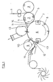
- the folding apparatus shown in FIG. 1 comprises a cross-cutting device for dividing a paper web 1 into sheet-shaped products and two cross-folding devices for folding these products around a folding line parallel to their front edge.
- the cross-cutting device consists of a knife arranged on an assigned cylinder 2 and a cutting groove assigned to it and arranged on a cylinder 3 rolling on cylinder 2. Puncture needles 4 are assigned to this, which are in the front edge area of the web that is created with each cut stab in the beginning.
- the cylinder 3 is provided with a folding knife 5 which is offset by 180 ° with respect to the cutting groove and which cooperates with folding flaps 7 arranged on a cylinder 6 rolling on the cylinder 3.
- the cylinder 6 is provided with folding jaws 7 arranged downstream of the folding jaws 8 to achieve the second transverse fold, which folding blades cooperate with a folding jaw 10 arranged on a further cylinder 9 rolling on the cylinder 6.
- the twice cross-folded products are removed from the cylinder 9 by means of a lifting device and fed to a belt line leading to a paddle wheel.
- Cylinders 6 and 9 are each provided with a guiding device 13, which serves to hold the product halves 14 lying on the circumferential section of the associated cylinder 3 or 6, which precedes the associated folding knife 5 or 8, after the folding process has taken place, the cylinder carrying the folding flaps 7 or 10 6 or 9 feed.
- a guiding device 13 serves to hold the product halves 14 lying on the circumferential section of the associated cylinder 3 or 6, which precedes the associated folding knife 5 or 8, after the folding process has taken place, the cylinder carrying the folding flaps 7 or 10 6 or 9 feed.
- the guide devices 13 consist, as shown in FIGS. 2 and 3, of a roller 14 forming a central part, freely rotatably mounted about an axis parallel to the cylinder, and two cylinders adjoining it on the cylinder side, one in the cylindrical outer surface of the Roller 14 tangentially cutting surface contour having stationary arranged connecting pieces 15 and 16.
- the multipart nature of the guide devices 13 ensures that only one part has to be replaced when a part wears.
- a distribution of the particularly strong wear attack, particularly in the central region results over the entire circumference of the roller.
- the jacket of the roller 14 and the connecting pieces 15, 16 are designed here as plastic moldings, which results in a particularly gentle product treatment due to the self-lubricating properties of plastic.
- the roller 14 and the connecting pieces 15, 16 can be provided with grooves in the region of their circumference or their guide surface.
- An embodiment of this type also enables the roller 14 and the connecting pieces 15, 16 to be galvanized mutually by engaging the roller-side webs in the connecting-piece grooves and vice versa. It would also be conceivable, instead of a continuous roller provided with two lateral bearing journals 17, to provide a plurality of rollers which are accommodated, for example, at a distance from one another on a common axis.
- connecting pieces 15, 16 a plurality of tongues, which are arranged next to one another at a distance, may be provided.
- a continuous roller 14 provided with two lateral bearing journals 17 and connecting pieces 15, 16 formed by continuous profile sections are provided.
- the roller 14 and the connecting pieces 15, 16 can be mounted separately on the machine frame.
- the roller 14 and the lateral connection pieces 15, 16 are accommodated on a common frame 18.
- this is arranged between the frame side walls 19 and suspended thereon.
- a cross member 20 is provided, which extends across the entire machine width and is attached to the frame side walls 19 and on which the frame 18 is received.
- two mutually opposite, coaxial stub axles could of course also be provided.
- the frame 18 consists of two lateral bearing blocks 21 which are pivotably received on the cross member 20 and which are connected to one another by axially parallel support rails 22, 23 arranged outside the roller 14.
- the bearing blocks 21 are provided with bearing bores associated with the bearing journals 17 of the roller 14.
- the connectors 15, 16 are attached to the support rails 22 and 23, which extend over the entire width of the frame 18.
- retaining screws 24 are provided for this.
- the bearing blocks 21 are in the area of the cross member 20 set bores each provided with a clamping slot 25 and an associated clamping screw 26. The clamping screws 26 are tightened as soon as the frame 18 is set to the desired pivot position.
- the bearing blocks 21 are provided with stationary bearings 27 assigned to the bearing journals 17 of the roller 14.
- the roller 14 in order to ensure an adjustable mounting of the roller 14, it may be appropriate to arrange the roller 14 so that it can be adjusted on the frame 18 in order to have an adjustment possibility as the roller diameter decreases.
- the lateral bearing pins 17 can engage in associated bearing shoes, which are slidably received on the bearing blocks 21.
- the connecting pieces 15, 16 can be pivoted or adjusted on the frame 18. In most cases, however, a rigid arrangement of the connecting pieces 15, 16 and a stationary mounting of the roller 14 are sufficient, which is the basis of the exemplary embodiment shown.
- the downstream cylinder here the cylinder 6, is enclosed by a brush 28 following the associated connector 16.
- the brush 28 its end on the frame side can be supported on the adjacent frame 18.
- the bristle carrier 29 of the brush 28 is provided with a support claw 30 in the illustrated embodiment, which rests snugly on the back of the adjacent connector 16.
- the support claw 30 is designed as a rigid component.
- the upstream cylinder 3 is surrounded by a band guide 31 following the associated connector 15. This connects practically continuously to the adjacent connector 15. The same also applies to the brush 26, which also continuously adjoins the adjacent connector 16.
Landscapes
- Folding Of Thin Sheet-Like Materials, Special Discharging Devices, And Others (AREA)
Applications Claiming Priority (2)
| Application Number | Priority Date | Filing Date | Title |
|---|---|---|---|
| DE3512308 | 1985-04-04 | ||
| DE19853512308 DE3512308A1 (de) | 1985-04-04 | 1985-04-04 | Falzapparat |
Publications (3)
| Publication Number | Publication Date |
|---|---|
| EP0197477A2 EP0197477A2 (de) | 1986-10-15 |
| EP0197477A3 EP0197477A3 (en) | 1988-11-30 |
| EP0197477B1 true EP0197477B1 (de) | 1991-04-03 |
Family
ID=6267280
Family Applications (1)
| Application Number | Title | Priority Date | Filing Date |
|---|---|---|---|
| EP86104358A Expired - Lifetime EP0197477B1 (de) | 1985-04-04 | 1986-03-29 | Falzapparat |
Country Status (4)
| Country | Link |
|---|---|
| US (1) | US4697805A (online.php) |
| EP (1) | EP0197477B1 (online.php) |
| JP (1) | JPH0662251B2 (online.php) |
| DE (2) | DE3512308A1 (online.php) |
Families Citing this family (14)
| Publication number | Priority date | Publication date | Assignee | Title |
|---|---|---|---|---|
| DE3705195A1 (de) * | 1987-02-19 | 1988-09-01 | Frankenthal Ag Albert | Leiteinrichtung |
| JPH0711079Y2 (ja) * | 1987-09-24 | 1995-03-15 | 株式会社小森コーポレーション | 折機の紙案内装置 |
| DE3914310A1 (de) * | 1989-04-29 | 1990-10-31 | Eltex Elektrostatik Gmbh | Vorrichtung zum abfuehren des staubes in falzapparaten fuer druckmaschinen |
| US5226871A (en) * | 1991-07-03 | 1993-07-13 | Rockwell International Corporation | Folder with gradual guide assembly and method |
| DE4234307A1 (de) * | 1992-10-12 | 1994-04-14 | Heidelberger Druckmasch Ag | Einrichtung zur störungsfreien Produktförderung in Falzapparaten |
| CA2146981A1 (en) * | 1992-12-22 | 1994-07-07 | David A. Smith | Flexible product folding and transferring apparatus and process |
| DE4342037C1 (de) * | 1993-12-09 | 1995-03-02 | Frankenthal Ag Albert | Verfahren und Vorrichtung zum Querfalzen von Signaturen |
| DE19515268C1 (de) * | 1995-04-26 | 1996-08-08 | Roland Man Druckmasch | Falzapparat zum wahlweisen Herstellen von einmal oder zweimal quergefalzten Produkten |
| DE19708213A1 (de) * | 1996-04-09 | 1997-10-30 | Heidelberger Druckmasch Ag | Verfahren und Vorrichtung zur Produktführung in einem Falzbildungsbereich eines Falzapparates |
| JP3415115B2 (ja) * | 2000-11-27 | 2003-06-09 | 株式会社東京機械製作所 | 折畳装置のガイド装置 |
| DE10215096B4 (de) * | 2002-04-05 | 2006-01-19 | Koenig & Bauer Ag | Heftapparat |
| ITMI20051482A1 (it) * | 2005-07-29 | 2007-01-30 | Officine G Cerutti S P A | Dispositivo per condurre delle segnature tra due cilindri di una piegatrice |
| US8002689B2 (en) * | 2006-03-06 | 2011-08-23 | Goss International Americas, Inc. | Folder with signature removal and slowdown process |
| US9878871B2 (en) * | 2012-12-31 | 2018-01-30 | Goss International Americas, Inc. | Dynamic guide for a paper folding machine |
Family Cites Families (20)
| Publication number | Priority date | Publication date | Assignee | Title |
|---|---|---|---|---|
| DE138846C (online.php) * | ||||
| DE388375C (de) * | 1921-07-10 | 1924-01-12 | Moriz & Kummer | Maschine zur Herstellung von Bloecken bedruckter und numerierter Blaetter |
| US1513575A (en) * | 1921-07-13 | 1924-10-28 | Cottrell C B & Sons Co | Folding mechanism |
| US1450574A (en) * | 1922-01-18 | 1923-04-03 | Cottrell C B & Sons Co | Sheet collecting and associating mechanism |
| US1803499A (en) * | 1927-07-15 | 1931-05-05 | Firm Vogtlandische Maschinenfa | Cutting and transferring mechanism for printing presses |
| US2138054A (en) * | 1936-05-07 | 1938-11-29 | Hoe & Co R | Folding mechanism for printing machines |
| US2131363A (en) * | 1937-03-01 | 1938-09-27 | Cottrell C B & Sons Co | Sheet collecting and folding mechanism for printing presses |
| US2164370A (en) * | 1937-09-10 | 1939-07-04 | Hoe & Co R | Folder for printing machines |
| US2659437A (en) * | 1947-03-04 | 1953-11-17 | Huck Co | Cutting and gripping mechanism for printing machines |
| GB691336A (en) * | 1950-12-21 | 1953-05-13 | Goss Printing Press Co Ltd | Improvements in or relating to delivery mechanism for folded and printed products |
| DE1132935B (de) * | 1958-09-25 | 1962-07-12 | Maschf Augsburg Nuernberg Ag | Trommelfalzeinrichtung zum Querfalzen und Sammeln an Bogendruckmaschinen |
| FR1350186A (fr) * | 1963-01-16 | 1964-01-24 | Leipzig Veb Druckmasch Werke | Dispositif de pliage pour machines à imprimer rotatives |
| FR1505567A (fr) * | 1966-11-04 | 1967-12-15 | Dispositif de pliage sur machines rotatives ou autres | |
| US3774907A (en) * | 1971-09-16 | 1973-11-27 | Xerox Corp | Vacuum sheet stripping apparatus |
| US4073485A (en) * | 1977-01-10 | 1978-02-14 | Gregg Engineering Corporation | Apparatus for making multiple page printed booklets |
| DE2931968B1 (de) * | 1979-08-07 | 1981-07-16 | Heidelberger Druckmaschinen Ag, 6900 Heidelberg | Falzapparat an Rollen-Rotationsdruckmaschinen |
| DE3030775C2 (de) * | 1980-08-14 | 1993-04-15 | Albert-Frankenthal Ag, 6710 Frankenthal | Falzapparat |
| JPS58114252U (ja) * | 1982-01-27 | 1983-08-04 | 小森印刷機械株式会社 | 折機の搬送ベルト機構 |
| DE3321577A1 (de) * | 1983-06-15 | 1984-12-20 | Heidelberger Druckmaschinen Ag, 6900 Heidelberg | Bremsbuersten im falzapparat von rotationsdruckmaschinen |
| US4519597A (en) * | 1984-05-10 | 1985-05-28 | The Lehigh Press, Inc. | Folding apparatus with compound tucker blade motion |
-
1985
- 1985-04-04 DE DE19853512308 patent/DE3512308A1/de active Granted
-
1986
- 1986-03-03 US US06/835,200 patent/US4697805A/en not_active Expired - Fee Related
- 1986-03-29 DE DE8686104358T patent/DE3678479D1/de not_active Expired - Lifetime
- 1986-03-29 EP EP86104358A patent/EP0197477B1/de not_active Expired - Lifetime
- 1986-03-31 JP JP61075377A patent/JPH0662251B2/ja not_active Expired - Lifetime
Also Published As
| Publication number | Publication date |
|---|---|
| EP0197477A3 (en) | 1988-11-30 |
| DE3512308C2 (online.php) | 1988-03-24 |
| DE3512308A1 (de) | 1986-10-16 |
| US4697805A (en) | 1987-10-06 |
| EP0197477A2 (de) | 1986-10-15 |
| DE3678479D1 (de) | 1991-05-08 |
| JPS61235364A (ja) | 1986-10-20 |
| JPH0662251B2 (ja) | 1994-08-17 |
Similar Documents
| Publication | Publication Date | Title |
|---|---|---|
| DE3904076C2 (online.php) | ||
| DE69315337T2 (de) | Maschine zum schneiden von bogen aus einer papierbahn und zum gleichzeitigen schneiden eines querstreifens | |
| EP0197477A2 (de) | Falzapparat | |
| DE2139159B2 (de) | Vorrichtung zum Breitstrecken von Warenbahnen, insbesondere von Papierbahnen | |
| DE1511272A1 (de) | Umlaufende Schneidvorrichtung zum Erzeugen geradliniger Schnitte quer durch fortlaufend bewegte Bahnen aus Papier oder Folienmaterial | |
| DE4223050C2 (de) | Vorrichtung zum Formschneiden vorlaufender Werkstoffbahnen | |
| DE69803880T2 (de) | Vorrichtung zum anbringen von aus einem kontinuierlichen schlauch hergestellten, wärmeschrumpfbaren hülsen auf gegenständen | |
| EP1116560B1 (de) | Schneidevorrichtung mit variabler Abschnittslänge | |
| DE10018772A1 (de) | Vorrichtung zum Querschneiden von mindestens einer Bahn in einem Falzapparat einer Rotationsdruckmaschine | |
| DE3903380C2 (online.php) | ||
| DE19708213A1 (de) | Verfahren und Vorrichtung zur Produktführung in einem Falzbildungsbereich eines Falzapparates | |
| DE2755000A1 (de) | Einstellvorrichtung fuer die messer eines zerspaners, insbesondere eines messerringzerspaners | |
| EP2128062B1 (de) | Splittingvorrichtung | |
| DE3124639C2 (de) | Vorrichtung zum Ausheben von Falzprodukten aus einem Falzklappenzylinder | |
| EP0920961B1 (de) | Vorrichtung zum Querschneiden von Materialbahnen | |
| EP0205116A2 (de) | Falzapparat | |
| DE1223682B (de) | Vorrichtung zum Aussortieren von Bogen aus Papier, Pappe od. dgl. | |
| DE19709485C2 (de) | Verfahren zum abschnittweisen Schneiden einer Bedruckstoffbahn in Längsrichtung und Schneideinrichtung hierfür | |
| DE19931002A1 (de) | Vorrichtung zum Verstellen des effektiven Zylinderdurchmessers | |
| DE9209633U1 (de) | Schneidvorrichtung | |
| DE19504607A1 (de) | Faserbandzuführvorrichtung für OE-Spinnmaschinen | |
| DE1963944C3 (de) | Aufbereitungsvorrichtung für Zuckerrohr | |
| DE10235897A1 (de) | Bedruckstoff verarbeitende Maschine mit einer Transportbandeinrichtung | |
| DE2647595A1 (de) | Maschine zum schneiden von papier | |
| DE19754151A9 (de) | Einrichtung zur Verbesserung der Falzgenauigkeit im Falzapparat |
Legal Events
| Date | Code | Title | Description |
|---|---|---|---|
| PUAI | Public reference made under article 153(3) epc to a published international application that has entered the european phase |
Free format text: ORIGINAL CODE: 0009012 |
|
| AK | Designated contracting states |
Kind code of ref document: A2 Designated state(s): CH DE FR GB IT LI |
|
| PUAL | Search report despatched |
Free format text: ORIGINAL CODE: 0009013 |
|
| AK | Designated contracting states |
Kind code of ref document: A3 Designated state(s): CH DE FR GB IT LI |
|
| 17P | Request for examination filed |
Effective date: 19890314 |
|
| 17Q | First examination report despatched |
Effective date: 19900810 |
|
| GRAA | (expected) grant |
Free format text: ORIGINAL CODE: 0009210 |
|
| AK | Designated contracting states |
Kind code of ref document: B1 Designated state(s): CH DE FR GB IT LI |
|
| GBT | Gb: translation of ep patent filed (gb section 77(6)(a)/1977) | ||
| REF | Corresponds to: |
Ref document number: 3678479 Country of ref document: DE Date of ref document: 19910508 |
|
| ET | Fr: translation filed | ||
| ITF | It: translation for a ep patent filed | ||
| PLBI | Opposition filed |
Free format text: ORIGINAL CODE: 0009260 |
|
| 26 | Opposition filed |
Opponent name: MAN ROLAND DRUCKMASCHINEN AG Effective date: 19911220 |
|
| PLBN | Opposition rejected |
Free format text: ORIGINAL CODE: 0009273 |
|
| STAA | Information on the status of an ep patent application or granted ep patent |
Free format text: STATUS: OPPOSITION REJECTED |
|
| 27O | Opposition rejected |
Effective date: 19930812 |
|
| PGFP | Annual fee paid to national office [announced via postgrant information from national office to epo] |
Ref country code: DE Payment date: 19980528 Year of fee payment: 13 |
|
| PGFP | Annual fee paid to national office [announced via postgrant information from national office to epo] |
Ref country code: GB Payment date: 19990222 Year of fee payment: 14 |
|
| PGFP | Annual fee paid to national office [announced via postgrant information from national office to epo] |
Ref country code: FR Payment date: 19990317 Year of fee payment: 14 |
|
| PGFP | Annual fee paid to national office [announced via postgrant information from national office to epo] |
Ref country code: CH Payment date: 19990331 Year of fee payment: 14 |
|
| PG25 | Lapsed in a contracting state [announced via postgrant information from national office to epo] |
Ref country code: DE Free format text: LAPSE BECAUSE OF NON-PAYMENT OF DUE FEES Effective date: 20000101 |
|
| PG25 | Lapsed in a contracting state [announced via postgrant information from national office to epo] |
Ref country code: GB Free format text: LAPSE BECAUSE OF NON-PAYMENT OF DUE FEES Effective date: 20000329 |
|
| PG25 | Lapsed in a contracting state [announced via postgrant information from national office to epo] |
Ref country code: LI Free format text: LAPSE BECAUSE OF NON-PAYMENT OF DUE FEES Effective date: 20000331 Ref country code: CH Free format text: LAPSE BECAUSE OF NON-PAYMENT OF DUE FEES Effective date: 20000331 |
|
| REG | Reference to a national code |
Ref country code: CH Ref legal event code: PL |
|
| GBPC | Gb: european patent ceased through non-payment of renewal fee |
Effective date: 20000329 |
|
| PG25 | Lapsed in a contracting state [announced via postgrant information from national office to epo] |
Ref country code: FR Free format text: LAPSE BECAUSE OF NON-PAYMENT OF DUE FEES Effective date: 20001130 |
|
| REG | Reference to a national code |
Ref country code: FR Ref legal event code: ST |
|
| PG25 | Lapsed in a contracting state [announced via postgrant information from national office to epo] |
Ref country code: IT Free format text: LAPSE BECAUSE OF NON-PAYMENT OF DUE FEES;WARNING: LAPSES OF ITALIAN PATENTS WITH EFFECTIVE DATE BEFORE 2007 MAY HAVE OCCURRED AT ANY TIME BEFORE 2007. THE CORRECT EFFECTIVE DATE MAY BE DIFFERENT FROM THE ONE RECORDED. Effective date: 20050329 |
|
| PLAB | Opposition data, opponent's data or that of the opponent's representative modified |
Free format text: ORIGINAL CODE: 0009299OPPO |