EP0196010A2 - Leuchtkasten - Google Patents
Leuchtkasten Download PDFInfo
- Publication number
- EP0196010A2 EP0196010A2 EP86103733A EP86103733A EP0196010A2 EP 0196010 A2 EP0196010 A2 EP 0196010A2 EP 86103733 A EP86103733 A EP 86103733A EP 86103733 A EP86103733 A EP 86103733A EP 0196010 A2 EP0196010 A2 EP 0196010A2
- Authority
- EP
- European Patent Office
- Prior art keywords
- light box
- box according
- cross
- strip
- Prior art date
- Legal status (The legal status is an assumption and is not a legal conclusion. Google has not performed a legal analysis and makes no representation as to the accuracy of the status listed.)
- Granted
Links
Images

Classifications
-
- G—PHYSICS
- G02—OPTICS
- G02B—OPTICAL ELEMENTS, SYSTEMS OR APPARATUS
- G02B27/00—Optical systems or apparatus not provided for by any of the groups G02B1/00 - G02B26/00, G02B30/00
- G02B27/02—Viewing or reading apparatus
- G02B27/022—Viewing apparatus
- G02B27/024—Viewing apparatus comprising a light source, e.g. for viewing photographic slides, X-ray transparancies
Definitions
- the invention relates to a light box for slides or the like. in an embodiment according to the preamble of claim 1.
- a special support frame is provided for each group of carrier disks, which can be inserted into the front of the outer frame and can be fixed in this by quick-release fasteners or by screws.
- the support frame is constructed in several parts and must be opened and closed again for a slide change.
- Such a configuration is relatively complicated, expensive to manufacture, cumbersome to handle when changing slides, and can only be achieved with light boxes with an angular contour.
- the invention has for its object to provide a particularly simple, inexpensive to produce light box of the type mentioned, which allows a quick and easy front-side slide change with secure support of the slide discs.
- the invention solves the problem starting from a light box of the type mentioned in the preamble of claim 1 primarily by the features specified in the characterizing part of claim 1. With regard to essential further refinements, reference is made to claims 2 to 10.
- the light box according to the invention is extremely simple and inexpensive to produce both from aluminum and from plastic.
- the slide between the supporting washers can be inserted directly into the outer frame from the front and are simply and securely fixed by the snap-on end profile strips.
- the end profile strips can be released quickly and without tools.
- they each form a decorative element on the front, since the cover part can be designed in various ways to achieve optical effects, regardless of its function in supporting the edges of the carrier disks.
- clamping profile part in the holding pocket, which is made of PVC, polyethylene or any other suitable elastic material, e.g. also rubber, can be made.
- This clamping profile part forms a compensating element in the event of tolerance deviations and changes in shape of the light box due to mechanical or thermal influences and at the same time increases the holding force with which the plug-in part of the end profile strip is fixed in the holding pocket.
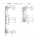
- the one-sided light box illustrated in FIG. 1 exists essentially from an outer frame 1, which is usually constructed from a number of frame struts placed together.
- the outer frame 1 or its frame struts or strips has a cross-sectional profile which comprises a thin wall part 2 and on the inside of which longitudinal extensions 3,4.
- the front longitudinal edge region 5 of the wall part 2 delimits a holding pocket 7 which is open at the front and which has an angular web 6 which extends along the inside thereof and in which a clamping profile part 18 made of elastic material, for example PVC or Polyethylene, is arranged.
- This clamping profile part 8 can extend as a strip along the entire length of the holding pocket 7.
- the clamping profile part 8 can also have the shape of sections of greater or lesser length, which can be arranged at a distance from one another over the length of the holding pocket 7.
- the clamping profile part is approximately U-shaped in cross-section, has inwardly curved side legs 9, 10 and a bottom leg 11.
- the clamping profile part 8 is provided with longitudinally extending, approximately semi-circular cross-sectional locking projections 12, 13 provided which engage in their cross-section approximately semicircular longitudinal grooves 14, 15 in the opposite walls of the holding pocket 7.
- the leg of the angular web 6 extending parallel to the wall part 2 or its longitudinal wall region 5 is provided with a provided inwardly projecting, longitudinal abutment web 17, which forms the inner abutment for two carrier disks 18, 19, between which a slide, not shown, is arranged.
- the carrier disk 19 generally forms a lens and the carrier disk 18 a clear disk.
- the carrier disks 18, 19 are held in their installed position by an end profile strip 20 which extends along the entire length of the holding pocket 7, i.e. extends along the entire circumferential length of the outer frame 1.
- the end profile strip 20 has a plug-in part 21 which engages in the pocket 16 in the clamping part 8, as can be seen particularly clearly in FIG. 3.
- the plug-in part 21 spreads out the inwardly curved side legs 9, 10, which bear against the plug-in part 21 due to the deformation under pressure.
- the plug-in part 21 can have a thickness increasing from the cover part 22 to its free end, as a result of which the fixing of the cover profile strip 20 is reinforced.
- the maximum thickness of the plug part 21 at its free end is somewhat less than the maximum width of the clear cross section of the pocket 16 in the clamping profile part 8, as is given at the height of the bottom leg 11 '. This ensures in connection with the dimensions of the parts, with respect to which reference is expressly made to FIG. 3, that the clamping profile part 8 can deform freely when the plug-in part 21 of the end profile strip 20 is inserted and leaves enough compensation play. In this context, it is preferred that the clamping profile part 8 engages with the walls of the holding pocket only in the region of the latching projections 12, 13? stands, i.e. is, so to speak, freely suspended.
- the cover part 22 of the end profile strip 20 engages over the holding pocket 7, closes on the outside with the outer surface of the wall part 2 of the outer frame 1 and projects inward beyond the angled web 6 so that it together with the abutment web 17 forms a groove-shaped pocket for the edge support of the carrier disc 18, 19.
- the back of the light box is closed by a rear wall 23 which can be fixed by screws which can be screwed into a longitudinal groove 24 in the molded attachment 4.
- One or more fluorescent tubes are accommodated in the interior of the light box, which can be supported together with the associated circuit components on the rear wall 23.
- webs 25, 26 can also be used, which extend parallel to the wall part 2 and are integrally formed on the angular web 6 or the shape attachment 4.
- the rear longitudinal edge region 5 'of the wall part 2 also delimits, with a corresponding angled web 6', a holding pocket 7 'which is open on the rear and which, with a corresponding end profile strip 20, provides an edge support of the same type for rear carrier disks 18', 19 'forms.
- the cross-sectional profile of the outer frame 1 is preferably symmetrical with respect to an imaginary central plane 27 parallel to the longitudinal edges of the wall part 2.
- the wall part 2 is provided on the inside with further longitudinal webs 28.
Landscapes
- Physics & Mathematics (AREA)
- General Physics & Mathematics (AREA)
- Optics & Photonics (AREA)
- Packaging Of Annular Or Rod-Shaped Articles, Wearing Apparel, Cassettes, Or The Like (AREA)
- Mirrors, Picture Frames, Photograph Stands, And Related Fastening Devices (AREA)
- Endoscopes (AREA)
- Microscoopes, Condenser (AREA)
- Non-Portable Lighting Devices Or Systems Thereof (AREA)
- Packaging Frangible Articles (AREA)
- Illuminated Signs And Luminous Advertising (AREA)
Abstract
Description
- Die Erfindung bezieht sich auf einen Leuchtkasten für Diapositive od.dgl. in einer Ausgestaltung nach dem Oberbegriff des Anspruchs 1.
- Bei einem bekannten, ein- oder doppelseitigen Leuchtkasten ist für jede Gruppe von Trägerscheiben ein besonderer Stützrahmen vorgesehen, der jeweils frontseitig in den Außenrahmen einsetzbar und in diesem durch Schnellverschlüsse oder durch Schrauben festlegbar ist. Der Stützrahmen ist mehrteilig ausgebildet und muß für einen Diawechsel geöffnet und wieder geschlossen werden. Eine derartige Ausgestaltung ist verhältnismäßig kompliziert, kostenträchtig in der Herstellung, umständlich in der Handhabung bei einem Diawechsel, und nur bei Leuchtkästen mit eckiger Kontur verwirklichbar.
- Der Erfindung liegt die Aufgabe zugrunde, einen besonders einfachen, preisgünstig herstellbaren Leuchtkasten der eingangs genannten Art zu schaffen, der bei sicherer Abstützung der Diaträgerscheiben einen schnellen und einfachen frontseitigen Diawechsel erlaubt.
- Die Erfindung löst die Aufgabe ausgehend von einem Leuchtkasten der im Oberbegriff des Anspruchs 1 genannten Art in erster Linie durch die im kennzeichnenden Teil des Anspruchs 1 angegebenen Merkmale. Hinsichtlich wesentlicher weiterer Ausgestaltungen wird auf die Ansprüche 2 bis 10 verwiesen.
- Der Leuchtkasten nach der Erfindung ist überaus einfach und preisgünstig sowohl aus Aluminium, als auch aus Kunststoff herstellbar.Die ein Diapositiv zwischen sich aufnehmenden Trägerscheiben sind jeweils frontseitig direkt in den Außenrahmen einsetzbar und werden durch die aufsteckbaren Abschlußprofilleisten einfach und sicher fixiert. Zu Diawechselzwecken können die Abschlußprofilleisten schnell und ohne Werkzeug gelöst werden. Sie bilden dabei zugleich ein jeweils frontseitiges Dekorelement, da der Abdeckteil ungeachtet seiner Funktion bei der Randabstützung der Trägerscheiben in vielfältiger Hinsicht zur Erzielung optischer Effekte gestaltbar ist.
- _ Bevorzugt befindet sich,in der Haltetasche ein annähernd U-förmiges, elastisch verformbares Klemmprofilteil, das aus PVC, Polyäthylen oder irgendeinem sonst geeigneten, elastischen Werkstoff,z.B. auch Gummi, hergestellt sein kann. Dieses Klemmprofilteil bildet ein Ausgleichselement bei Toleranzabweichungen und Formveränderungen des Leuchtkastens aufgrund von mechanischen oder thermischen Einflüssen und erhöht zugleich die Haltekraft, mit der der Steckteil der Abschlußprofilleiste in der Haltetasche festgelegt ist.
- Weitere Einzelheiten und Vorteile der Erfindung ergeben sich aus der nachfolgenden Beschreibung und der Zeichnung, in der zwei Ausführungsbeispiele des Gegenstands der Erfindung näher veranschaulicht sind. Im einzelnen zeigen:
- Fig. 1 einen abgebrochenen Schnitt durch einen einseitigen Leuchtkasten nach der Erfindung,
- Fig. 2 eine Darstellung ähnlich Fig. 1 eines erfindungsgemäßen Leuchtkastens in doppelseitiger Ausführung, und
- Fig. 3 eine abgebrochene Ausschnittsvergrößerung eines Randbereiches des Querschnittsprofils des Außenrahmens.
- Der in Fig. 1 veranschaulichte einseitige Leuchtkasten besteht im wesentlichen aus einem Außenrahmen 1, der in der Regel aus einer Anzahl von aneinander-gesetzten Rahmenstreben aufgebaut ist. Der Außenrahmen 1 bzw. dessen Rahmenstreben oder -leisten hat ein Querschnittsprofil, das einen dünnen Wandteil 2 und an dessen Innenseite längslaufende Formansätze 3,4 umfaßt. Wie der Fig. 1 und insbesondere der Fig. 3 entnommen werden kann, begrenzt der vordere Längsrandbereich 5 des Wandteils 2 mit einem sich innenseitig längs diesem erstreckenden Winkelsteg 6 eine vorderseitig offene Haltetasche 7, in der ein Klemmprofiltei18-aus elastischem Material, z.B. PVC oder Polyäthylen, angeordnet ist. Dieses Klemmprofilteil 8 kann sich als Leiste entlang der gesamten Länge der Haltetasche 7 erstrecken. Jedoch kann das Klemmprofilteil 8 auch die Gestalt von Abschnitten mehr oder weniger großer Länge haben, die mit gegenseitigem Abstand über die Länge der Haltetasche 7 verteilt in dieser angeordnet werden können.
- Das Klemmprofilteil ist im Querschnitt annähernd U-förmig, besitzt einwärts gebogene Seitenschenkel 9,10 und einen Bodenschenkel 11. An der Außenseite der Seitenschenkel 9,10 und entlang deren freien Ränder ist das Klemmprofilteil 8 mit längslaufenden, im Querschnitt etwa halbkreisförmigen Rastansätzen 12,13 versehen, die in ihrerseits im Querschnitt etwa halbkreisförmigen Längsnuten 14,15 in den gegenüberliegenden Wänden der Haltetasche 7 eingreifen. Dadurch ist das Klemmprofilteil 8 in der Haltetasche 7 arretiert,ohne daß die Verformbarkeit der Seitenschenkel 9,10 beeinträchtigt wird. Die Seitenschenkel 9,10 begrenzen zusammen mit dem Bodenschenkel 11 ihrerseits eine Tasche 16, deren lichter Querschnitt sich infolge der bogenförmigen Wölbung der Seitenschenkel 9,10 von der Eintrittsöffnung in Höhe der Rastansätze 12,13 zum Bodenschenkel 11 hin zunächst verengt und dann wieder erweitert.
- Der sich parallel zum Wandteil 2 bzw. dessen Längswandbereich 5 erstreckende Schenkel des Winkelstegs 6 ist mit einem einwärts vorspringenden, längslaufenden Widerlagersteg 17 versehen, der das innere Widerlager für zwei Trägerscheiben 18, 19 bildet, zwischen denen ein nicht veranschaulichtes Diapositiv angeordnet wird. Die Trägerscheibe 19 bildet dabei in der Regel eine-Streuscheibe und die Trägerscheibe 18 eine Klarscheibe.
- Die Trägerscheiben 18,19 werden in ihrer Einbaustellung durch eine Abschlußprofilleiste 20 gehalten, die sich längs der gesamten Länge der Haltetasche 7, d.h. entlang der gesamten Umfangslänge des Außenrahmens 1 erstreckt. Die Abschlußprofilleiste 20 weist einen Steckteil 21 auf, der in die Tasche 16 im Klemmprof ilteil 8 eingreift, wie dies die Fig. 3 besonders deutlich erkennen läßt. Der Steckteil 21 spreizt bei seinem Einführen in die Tasche 16 des Klemmprofilteils 8 die einwärts gewölbten Seitenschenkel 9,10 auf, die sich an den Steckteil 21 aufgrund der Verformung unter Druck anlegen. Der Steckteil 21 kann wie dargestellt eine vom Abdeckteil 22 zu seinem freien Ende hin ansteigende Dicke aufweisen, wodurch die Festlegung der Abdeckprofilleiste 20 verstärkt wird. Die maximale Dicke des Steckteils 21 an dessen freien Ende ist etwas geringer als die maximale Breite des lichten Querschnitts der Tasche 16 im Klemmprofilteil 8, wie sie in Höhe des Bodenschenkels 11' gegeben ist. Dies sichert in Verbindung der Abmessung der Teile, hinsichtlich der ausdrücklich auf Fig. 3 verwiesen wird, daß sich das Klemmprofilteil 8 beim Einführen des Steckteils 21 der Abschlußprofilleiste 20 frei verformen kann und genügend Ausgleichsspiel beläßt. Bevorzugt ist in diesem Zusammenhang, daß das Klemmprofilteil 8 nur im Bereich der Rastansätze 12,13 in Eingriff mit den Wänden der Haltetasche ? steht, d.h. gewissermaßen frei eingehängt ist.
- Der Abdeckteil 22 der Abschlußprofilleiste 20 übergreift die Haltetasche 7, schließt außenseitig mit der Außenfläche des Wandteils 2 des Außenrahmens 1 ab und steht einwärts über den Winkelsteg 6 vor, so daß er zusammen mit dem Widerlagersteg 17 eine nutförmige Tasche für die Randabstützung der Trägerscheibei18,19 bildet.
- Bei der Ausführung nach Fig. 1 ist die Rückseite des Leuchtkastens durch eine Rückwand 23 verschlossen, die durch Schrauben festlegbar ist, welche in eine Längsnut 24 im Formansatz 4 einschraubbar sind. Im Innern des Leuchtkastens sind eine oder mehrere Leuchtstoffröhren untergebracht, die sich zusammen mit den zugehörigen Schaltungsbauteilen an der Rückwand 23 abstützen können. Zur Abstützung können jedoch auch Stege 25,26 verwendet werden, die sich parallel zum Wandteil 2 erstrecken und am Winkelsteg 6 bzw. Formansatz 4 angeformt sind.
- Bei der in Fig. 2 veranschaulichten doppelseitigen Ausführung des Leuchtkastens begrenzt auch der rückseitige Längsrandbereich 5' des Wandteils 2 mit einem entsprechenden Winkelsteg 6' eine rückseitig offene Haltetasche 7', die mit einer entsprechenden Abschlußprofilleiste 20 eine Randabstützung gleicher Art für rückseitige Trägerscheiben 18',19' bildet. Bevorzugt ist das Querschnittsprofil des Außenrahmens 1 zu einer zu den Längsrändern des Wandteils 2 parallelen, gedachten Mittelebene 27 symmetrisch.
- Zur Absützung von Leuchtstoffröhren ist der Wandteil 2 innenseitig mit weiteren längslaufenden Stegen 28 versehen.
Claims (10)
Priority Applications (1)
| Application Number | Priority Date | Filing Date | Title |
|---|---|---|---|
| AT86103733T ATE81214T1 (de) | 1985-03-23 | 1986-03-19 | Leuchtkasten. |
Applications Claiming Priority (2)
| Application Number | Priority Date | Filing Date | Title |
|---|---|---|---|
| DE3510594 | 1985-03-23 | ||
| DE19853510594 DE3510594A1 (de) | 1985-03-23 | 1985-03-23 | Leuchtkasten |
Publications (3)
| Publication Number | Publication Date |
|---|---|
| EP0196010A2 true EP0196010A2 (de) | 1986-10-01 |
| EP0196010A3 EP0196010A3 (en) | 1987-11-11 |
| EP0196010B1 EP0196010B1 (de) | 1992-09-30 |
Family
ID=6266137
Family Applications (1)
| Application Number | Title | Priority Date | Filing Date |
|---|---|---|---|
| EP86103733A Expired - Lifetime EP0196010B1 (de) | 1985-03-23 | 1986-03-19 | Leuchtkasten |
Country Status (4)
| Country | Link |
|---|---|
| US (1) | US4766685A (de) |
| EP (1) | EP0196010B1 (de) |
| AT (1) | ATE81214T1 (de) |
| DE (2) | DE3510594A1 (de) |
Cited By (1)
| Publication number | Priority date | Publication date | Assignee | Title |
|---|---|---|---|---|
| EP2933554A1 (de) * | 2014-04-16 | 2015-10-21 | NORKA Norddeutsche Kunststoff- und Elektro-Gesellschaft Stäcker mbH & Co.KG. | Leuchte und Verfahren zum Zusammenbau einer Leuchte |
Families Citing this family (6)
| Publication number | Priority date | Publication date | Assignee | Title |
|---|---|---|---|---|
| US4851971A (en) * | 1988-06-20 | 1989-07-25 | Maclagan James A | Transparency illuminator |
| GB9201503D0 (en) * | 1992-01-24 | 1992-03-11 | Showcard Systems Retail Ltd | Lightbox for display purposes |
| US5826973A (en) * | 1995-09-14 | 1998-10-27 | Melzian; John M. | Illuminated display with uniform luminance |
| GB2388949A (en) * | 2002-05-22 | 2003-11-26 | Peter Alan Lee | Illuminated advertising display device |
| US7377061B2 (en) * | 2004-10-04 | 2008-05-27 | Target Brands, Inc. | Light box display |
| DE102007063335A1 (de) * | 2007-12-27 | 2009-07-02 | Herbert Waldmann Gmbh & Co. Kg | Leuchte |
Citations (4)
| Publication number | Priority date | Publication date | Assignee | Title |
|---|---|---|---|---|
| GB348148A (de) * | 1900-01-01 | |||
| FR2076126A1 (de) * | 1970-01-15 | 1971-10-15 | Grieger Karl | |
| WO1982004130A1 (en) * | 1981-05-12 | 1982-11-25 | Ohlson Carl Eric | A fixing means for mounting x-ray films |
| US4385462A (en) * | 1978-01-12 | 1983-05-31 | Knox Manufacturing Co. | Illuminated transparency viewing system with overlay device and film clips |
Family Cites Families (4)
| Publication number | Priority date | Publication date | Assignee | Title |
|---|---|---|---|---|
| US1746943A (en) * | 1927-11-04 | 1930-02-11 | Volney L Hofmann | Sign |
| US2163329A (en) * | 1937-09-15 | 1939-06-20 | Casimir J Sipior | Display device |
| US2303988A (en) * | 1940-11-04 | 1942-12-01 | Christensen Geneva Bandy | Transparency displaying device |
| US3500569A (en) * | 1968-01-04 | 1970-03-17 | Dimensional Concepts Inc | Portable display unit |
-
1985
- 1985-03-23 DE DE19853510594 patent/DE3510594A1/de not_active Withdrawn
-
1986
- 1986-03-10 US US06/838,087 patent/US4766685A/en not_active Expired - Fee Related
- 1986-03-19 EP EP86103733A patent/EP0196010B1/de not_active Expired - Lifetime
- 1986-03-19 AT AT86103733T patent/ATE81214T1/de not_active IP Right Cessation
- 1986-03-19 DE DE8686103733T patent/DE3686829D1/de not_active Expired - Fee Related
Patent Citations (4)
| Publication number | Priority date | Publication date | Assignee | Title |
|---|---|---|---|---|
| GB348148A (de) * | 1900-01-01 | |||
| FR2076126A1 (de) * | 1970-01-15 | 1971-10-15 | Grieger Karl | |
| US4385462A (en) * | 1978-01-12 | 1983-05-31 | Knox Manufacturing Co. | Illuminated transparency viewing system with overlay device and film clips |
| WO1982004130A1 (en) * | 1981-05-12 | 1982-11-25 | Ohlson Carl Eric | A fixing means for mounting x-ray films |
Cited By (2)
| Publication number | Priority date | Publication date | Assignee | Title |
|---|---|---|---|---|
| EP2933554A1 (de) * | 2014-04-16 | 2015-10-21 | NORKA Norddeutsche Kunststoff- und Elektro-Gesellschaft Stäcker mbH & Co.KG. | Leuchte und Verfahren zum Zusammenbau einer Leuchte |
| WO2015158405A1 (de) * | 2014-04-16 | 2015-10-22 | NORKA Norddeutsche Kunststoff- und Elektro-Gesellschaft Stäcker mbH & Co. KG | Leuchte und verfahren zum zusammenbau einer leuchte |
Also Published As
| Publication number | Publication date |
|---|---|
| EP0196010B1 (de) | 1992-09-30 |
| DE3686829D1 (de) | 1992-11-05 |
| ATE81214T1 (de) | 1992-10-15 |
| US4766685A (en) | 1988-08-30 |
| EP0196010A3 (en) | 1987-11-11 |
| DE3510594A1 (de) | 1986-09-25 |
Similar Documents
| Publication | Publication Date | Title |
|---|---|---|
| DE2841345C2 (de) | Tragbares Display System | |
| EP0444519A1 (de) | Dekorationsgegenstand mit beleuchteten Profilschienen | |
| DE1547622A1 (de) | Werbeschild | |
| EP0196010B1 (de) | Leuchtkasten | |
| DE2943544A1 (de) | Langgestreckte bandfoermige lampe | |
| DE2608518A1 (de) | Reflektormantel | |
| EP1825452B1 (de) | Halter | |
| DE3003367A1 (de) | Bausatz fuer die herstellung von zargen fuer korpusse | |
| DE3123193A1 (de) | "adapterteil fuer wort- bild- und tontraegergehaeuse" | |
| DE2718073B2 (de) | Verdunkelungsblendenvorrichtung für ein Periskop | |
| EP0569326A1 (de) | Prisma zur Präsentation von Informationsträgern | |
| DE10341494B4 (de) | Schlüsselkasten | |
| DE2642327A1 (de) | Transport- und lagerkasten aus kunststoff | |
| DE3113649C2 (de) | Blendrahmen aus Strangpreßprofil-Holmen und hiermit ausgestattetes kastenförmiges Lichtwerbeelement | |
| DE102017117313A1 (de) | Halter, Kennzeichenhalterung sowie Verfahren und Verwendung hierzu | |
| EP0354488A2 (de) | Befestigungsvorrichung für Schriftträger | |
| DE3141132A1 (de) | "fuehrungsschiene fuer rollaeden o.dgl." | |
| DE2532110A1 (de) | Gehaeuse fuer elektronische bauteile | |
| DE2336659A1 (de) | Informationsschild | |
| AT408283B (de) | Türsprechanlage mit einer geräte-frontplatte | |
| DE2042765C3 (de) | Beleuchtbarer Vorhangschienenkasten mit einer Vorhang-Tragschiene | |
| DE60214997T2 (de) | Profil und satz von mehreren elementen mit einem oder mehreren solcher profilen | |
| DE6806932U (de) | Reklame-leuchtkoerper | |
| DE2042734C3 (de) | Trennschiene zum Einbau in Kabel-Installationskanälen | |
| DE1539546C (de) | Langgestrecktes Flutlichtgerät |
Legal Events
| Date | Code | Title | Description |
|---|---|---|---|
| PUAI | Public reference made under article 153(3) epc to a published international application that has entered the european phase |
Free format text: ORIGINAL CODE: 0009012 |
|
| AK | Designated contracting states |
Kind code of ref document: A2 Designated state(s): AT BE CH DE FR GB IT LI LU NL SE |
|
| PUAL | Search report despatched |
Free format text: ORIGINAL CODE: 0009013 |
|
| AK | Designated contracting states |
Kind code of ref document: A3 Designated state(s): AT BE CH DE FR GB IT LI LU NL SE |
|
| 17P | Request for examination filed |
Effective date: 19880116 |
|
| TCNL | Nl: translation of patent claims filed | ||
| 17Q | First examination report despatched |
Effective date: 19900606 |
|
| RAP1 | Party data changed (applicant data changed or rights of an application transferred) |
Owner name: HINRICHS FOTOWERBUNG GMBH |
|
| GRAA | (expected) grant |
Free format text: ORIGINAL CODE: 0009210 |
|
| AK | Designated contracting states |
Kind code of ref document: B1 Designated state(s): AT BE CH DE FR GB IT LI LU NL SE |
|
| REF | Corresponds to: |
Ref document number: 81214 Country of ref document: AT Date of ref document: 19921015 Kind code of ref document: T |
|
| ITF | It: translation for a ep patent filed |
Owner name: BARZANO' E ZANARDO MILA |
|
| REF | Corresponds to: |
Ref document number: 3686829 Country of ref document: DE Date of ref document: 19921105 |
|
| GBT | Gb: translation of ep patent filed (gb section 77(6)(a)/1977) | ||
| ET | Fr: translation filed | ||
| PLBE | No opposition filed within time limit |
Free format text: ORIGINAL CODE: 0009261 |
|
| STAA | Information on the status of an ep patent application or granted ep patent |
Free format text: STATUS: NO OPPOSITION FILED WITHIN TIME LIMIT |
|
| 26N | No opposition filed | ||
| EPTA | Lu: last paid annual fee | ||
| EAL | Se: european patent in force in sweden |
Ref document number: 86103733.1 |
|
| PGFP | Annual fee paid to national office [announced via postgrant information from national office to epo] |
Ref country code: LU Payment date: 19950301 Year of fee payment: 10 |
|
| PGFP | Annual fee paid to national office [announced via postgrant information from national office to epo] |
Ref country code: GB Payment date: 19950313 Year of fee payment: 10 |
|
| PGFP | Annual fee paid to national office [announced via postgrant information from national office to epo] |
Ref country code: SE Payment date: 19950320 Year of fee payment: 10 |
|
| PGFP | Annual fee paid to national office [announced via postgrant information from national office to epo] |
Ref country code: CH Payment date: 19950323 Year of fee payment: 10 |
|
| PGFP | Annual fee paid to national office [announced via postgrant information from national office to epo] |
Ref country code: FR Payment date: 19950329 Year of fee payment: 10 Ref country code: AT Payment date: 19950329 Year of fee payment: 10 |
|
| PGFP | Annual fee paid to national office [announced via postgrant information from national office to epo] |
Ref country code: BE Payment date: 19950330 Year of fee payment: 10 |
|
| PGFP | Annual fee paid to national office [announced via postgrant information from national office to epo] |
Ref country code: NL Payment date: 19950331 Year of fee payment: 10 |
|
| PG25 | Lapsed in a contracting state [announced via postgrant information from national office to epo] |
Ref country code: LU Free format text: LAPSE BECAUSE OF NON-PAYMENT OF DUE FEES Effective date: 19960319 Ref country code: GB Effective date: 19960319 Ref country code: AT Effective date: 19960319 |
|
| PG25 | Lapsed in a contracting state [announced via postgrant information from national office to epo] |
Ref country code: SE Effective date: 19960320 |
|
| PG25 | Lapsed in a contracting state [announced via postgrant information from national office to epo] |
Ref country code: LI Effective date: 19960331 Ref country code: CH Effective date: 19960331 Ref country code: BE Effective date: 19960331 |
|
| BERE | Be: lapsed |
Owner name: HINRICHS FOTOWERBUNG G.M.B.H. Effective date: 19960331 |
|
| PG25 | Lapsed in a contracting state [announced via postgrant information from national office to epo] |
Ref country code: NL Effective date: 19961001 |
|
| GBPC | Gb: european patent ceased through non-payment of renewal fee |
Effective date: 19960319 |
|
| REG | Reference to a national code |
Ref country code: CH Ref legal event code: PL |
|
| PG25 | Lapsed in a contracting state [announced via postgrant information from national office to epo] |
Ref country code: FR Effective date: 19961129 |
|
| NLV4 | Nl: lapsed or anulled due to non-payment of the annual fee |
Effective date: 19961001 |
|
| EUG | Se: european patent has lapsed |
Ref document number: 86103733.1 |
|
| REG | Reference to a national code |
Ref country code: FR Ref legal event code: ST |
|
| PGFP | Annual fee paid to national office [announced via postgrant information from national office to epo] |
Ref country code: DE Payment date: 19990416 Year of fee payment: 14 |
|
| PG25 | Lapsed in a contracting state [announced via postgrant information from national office to epo] |
Ref country code: DE Free format text: LAPSE BECAUSE OF NON-PAYMENT OF DUE FEES Effective date: 20010103 |
|
| PG25 | Lapsed in a contracting state [announced via postgrant information from national office to epo] |
Ref country code: IT Free format text: LAPSE BECAUSE OF NON-PAYMENT OF DUE FEES Effective date: 20050319 |