EP0192169A2 - Vorrichtung zum berührungsfreien Führen von Warenbahnen, insbesondere Metallbändern, mittels eines Gasmediums - Google Patents
Vorrichtung zum berührungsfreien Führen von Warenbahnen, insbesondere Metallbändern, mittels eines Gasmediums Download PDFInfo
- Publication number
- EP0192169A2 EP0192169A2 EP86101729A EP86101729A EP0192169A2 EP 0192169 A2 EP0192169 A2 EP 0192169A2 EP 86101729 A EP86101729 A EP 86101729A EP 86101729 A EP86101729 A EP 86101729A EP 0192169 A2 EP0192169 A2 EP 0192169A2
- Authority
- EP
- European Patent Office
- Prior art keywords
- nozzle boxes
- web
- nozzle
- boxes
- gas
- Prior art date
- Legal status (The legal status is an assumption and is not a legal conclusion. Google has not performed a legal analysis and makes no representation as to the accuracy of the status listed.)
- Granted
Links
Images

Classifications
-
- B—PERFORMING OPERATIONS; TRANSPORTING
- B65—CONVEYING; PACKING; STORING; HANDLING THIN OR FILAMENTARY MATERIAL
- B65H—HANDLING THIN OR FILAMENTARY MATERIAL, e.g. SHEETS, WEBS, CABLES
- B65H23/00—Registering, tensioning, smoothing or guiding webs
- B65H23/04—Registering, tensioning, smoothing or guiding webs longitudinally
- B65H23/24—Registering, tensioning, smoothing or guiding webs longitudinally by fluid action, e.g. to retard the running web
-
- B—PERFORMING OPERATIONS; TRANSPORTING
- B65—CONVEYING; PACKING; STORING; HANDLING THIN OR FILAMENTARY MATERIAL
- B65H—HANDLING THIN OR FILAMENTARY MATERIAL, e.g. SHEETS, WEBS, CABLES
- B65H20/00—Advancing webs
- B65H20/14—Advancing webs by direct action on web of moving fluid
-
- C—CHEMISTRY; METALLURGY
- C21—METALLURGY OF IRON
- C21D—MODIFYING THE PHYSICAL STRUCTURE OF FERROUS METALS; GENERAL DEVICES FOR HEAT TREATMENT OF FERROUS OR NON-FERROUS METALS OR ALLOYS; MAKING METAL MALLEABLE, e.g. BY DECARBURISATION OR TEMPERING
- C21D9/00—Heat treatment, e.g. annealing, hardening, quenching or tempering, adapted for particular articles; Furnaces therefor
- C21D9/52—Heat treatment, e.g. annealing, hardening, quenching or tempering, adapted for particular articles; Furnaces therefor for wires; for strips ; for rods of unlimited length
- C21D9/54—Furnaces for treating strips or wire
- C21D9/56—Continuous furnaces for strip or wire
- C21D9/63—Continuous furnaces for strip or wire the strip being supported by a cushion of gas
-
- B—PERFORMING OPERATIONS; TRANSPORTING
- B65—CONVEYING; PACKING; STORING; HANDLING THIN OR FILAMENTARY MATERIAL
- B65H—HANDLING THIN OR FILAMENTARY MATERIAL, e.g. SHEETS, WEBS, CABLES
- B65H2406/00—Means using fluid
- B65H2406/10—Means using fluid made only for exhausting gaseous medium
- B65H2406/11—Means using fluid made only for exhausting gaseous medium producing fluidised bed
- B65H2406/112—Means using fluid made only for exhausting gaseous medium producing fluidised bed for handling material along preferably rectilinear path, e.g. nozzle bed for web
Definitions
- the invention relates to a device for the contact-free guiding of material webs, in particular metal strips, by means of a gas medium with nozzle boxes arranged above and below and at a distance from the material web, each having a nozzle outlet plane, between which gas extraction channels are provided above and below the material web.
- Air or inert gas is mainly used as the gas medium, which is blown against the material web.
- the critical strip thickness can still be less than 0.3 mm.
- the metal strip of the corresponding thickness or stiffness emerging from the device rather has an impermissibly high proportion of longitudinal folds and other unevenness, so that a high proportion of rejects must be expected.
- a device is also known (DE-PS 33 18 861) through which webs of material, in particular aluminum strips, can be guided in a floating manner for the purpose of an annealing treatment.
- nozzle boxes extending transversely to the transport direction of the material webs are used, each of which has two longitudinal slots or rows of holes to form air cushions, the blowing directions of which are inclined towards one another.
- These shower boxes are arranged in pairs above and below the web. Such a pair of nozzle boxes arranged above the product line is then followed by a further pair of nozzle boxes in the transport direction below the product line. This pair is then connected to a further pair of nozzle boxes in the transport direction above the web.
- the load capacity of the gas jets emerging from the nozzle boxes and inclined towards one another is very low, so that this device cannot be considered for relatively thick and heavy metal strips.
- the nozzle boxes in this device must be designed to be quite complex, this known device cannot be used to produce the optimal sinusoidal shape for the carrying and guiding effect.
- the invention is based on the object of designing a device of the type mentioned at the outset in such a way that it can be used to run both relatively thin and relatively thick and / or rigid strip material, in particular metal strip, in a contact-free manner in a sinusoidal wavy line, for heating or cooling a high power density should be achievable.
- nozzle outlet planes of the nozzle boxes arranged above and below the web have spacings which differ individually or in groups in relation to a substantially horizontal plane corresponding to the transport direction of the web.
- the distance between the upper and lower nozzle boxes from the web can be selected according to the load to be carried.
- the nozzle boxes can have one or more rows of nozzles, it being possible to use slot nozzles and nozzles with a round, oval or other shaped nozzle opening.
- Air is particularly suitable as the gas medium.
- the individual nozzle boxes which are arranged above and below the web, are placed in the device in accordance with the desired, possibly sinusoidal, course of the web.
- the device according to the invention can also be designed so that the nozzle boxes above and below the web are distributed over essentially the same bandwidth.
- the device according to the invention can also be designed such that the nozzle boxes arranged above the web are offset from the nozzle boxes below the web in the direction of transport. It is possible for a nozzle box on the top of the web to be aligned centrally with two nozzle boxes arranged on the bottom of the web and vice versa. Other offset relations are also possible.
- the device according to the invention can also be designed such that the nozzle boxes arranged above the web are offset from the nozzle boxes arranged below the web transversely to the direction of transport.
- the device according to the invention can also be designed such that at least some of the nozzle boxes can be adjusted vertically with respect to a substantially horizontal plane corresponding to the direction of transport. With such an adjustability, the course of the web in the device can be changed. In particular, adaptation to changing material webs and material properties is possible.
- the device according to the invention can be so forms that at least some of the adjustable nozzle boxes can be adjusted together. In this way, the adjustability of the nozzle boxes with respect to the web can be simplified and thus accelerated.
- Fig. La shows schematically a device A in the form of a heating furnace or a cooling device.
- This device A has a fan B, the gas flows in via pressure channels C.
- Nozzle boxes D promotes.
- the gas emerges from the nozzle boxes D and hits a web E. From here, the gas is fed back to the fan B via an intake duct F.
- Heating or cooling elements for the gas streams can be provided in the pressure channels C and / or the intake channel F.
- a web in the form of a metal strip 1 is passed through the device shown in FIG. 1.
- Upper nozzle boxes 2 to 5 are arranged above the metal strip 1.
- Under the metal strip 1 there are opposing lower nozzle boxes 6 to 9.
- the nozzle boxes 2 to 9 are at different distances from this central plane 10 arranged.
- the upper nozzle boxes 2 and 4 and the w änteren nozzle boxes are disposed 7 and 9 with the same distance from the center plane 10 degrees.
- the upper nozzle boxes 3 and 5 and the lower nozzle boxes 6 and 8 are also at the same distance from one another from the imaginary center plane 10.
- the arrows 11 emerging from each nozzle box 2 to 9 in the direction of the metal strip 1 are intended to exit from the nozzles of each nozzle box 2 to 9 represent emerging gas flows.
- the upper nozzle boxes 2 to 5 are arranged offset relative to the lower nozzle boxes 6 to 9 in the direction of transport of the metal strip 1 indicated by an arrow 12.
- the metal strip 1 When the metal strip 1 is subjected to gas flows, e.g. Air or protective gas, the metal strip 1 takes a sinusoidal shape from the nozzle boxes 2 to 9.
- gas flows e.g. Air or protective gas
- adjustable throttle valves 14 to 19 are attached, with which the amount of gas to be discharged from the treatment room can be adjusted.
- adjustable throttle valves 14 to 19 fixed throttle plates or the like can also be used.
- the upper throttle valves 14 to 16 or the lower throttle valves 17 to 19 can also be dispensed with in whole or in part.
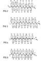
- the embodiment of the device according to FIG. 2 is particularly suitable for treating particularly stiff or relatively thick metal strip 1.
- the distance from the upper nozzle boxes 20 to 27 and lower nozzle boxes 28 to 34 to the central plane 10 is changed over the length of the metal strip 1 in smaller increments than in the embodiment according to FIG. 1.
- the sinusoidal line that the metal strip 1 is correspondingly flat is thus follows when it is transported through the device.
- throttle devices (not shown) can be present in gas discharge channels 35 between the individual nozzle boxes 20 to 34.
- the embodiment according to FIG. 3 is also particularly suitable for relatively stiff and thick metal strip 1.
- the nozzle boxes 36 to 53 are arranged at the same distance from the central plane 10.
- the nozzle boxes 39 to 41 and 48 to 50 have different, mutually different distances from the central plane 10.
- throttle devices can be provided in a suitable manner in gas exhaust channels 54 between the nozzle boxes 36 to 53.
- nozzle boxes 70 to 84 are provided which are not offset as a whole perpendicular to the surface of the metal strip 1 or the central plane 10; rather, only the surfaces of the nozzle boxes 70 to 84 provided with nozzles are arranged in the manner shown perpendicular to the surface of the metal strip 1 and thus offset to the central plane 10.
Landscapes
- Chemical & Material Sciences (AREA)
- Engineering & Computer Science (AREA)
- Materials Engineering (AREA)
- Thermal Sciences (AREA)
- Crystallography & Structural Chemistry (AREA)
- Mechanical Engineering (AREA)
- Physics & Mathematics (AREA)
- Metallurgy (AREA)
- Organic Chemistry (AREA)
- Advancing Webs (AREA)
- Heat Treatment Of Strip Materials And Filament Materials (AREA)
- Delivering By Means Of Belts And Rollers (AREA)
- Manufacturing Of Electric Cables (AREA)
Abstract
Description
- Die Erfindung betrifft eine Vorrichtung zum beruhrungsfreien FUhren von Warenbahnen, insbesondere Metallbändern, mittels eines Gasmediums mit oberhalb und unterhalb in Abstand von der Warenbahn angeordneten, jeweils eine Düsenaustrittsebene aufweisenden Düsenkästen, zwischen denen oberhalb und unterhalb der Warenbahn Gasabzugskanäle vorgesehen sind.
- Derartige Vorrichtungen dienen insbesondere zum Erwärmen oder Kühlen von band- oder bahnförmigem Material. Als Gasmedium wird dabei überwiegend Luft oder Schutzgas eingesetzt, die gegen die Warenbahn geblasen wird.
- Es ist bereits bekannt (DE-AS 25 21 017), Warenbahnen, insbesondere Metallbänder, mit einer Dicke von 0,1 mm und mehr gleichmäßig und ebenflächig durch einen Spalt zwischen entgegengerichteten DUsenkästen hindurchzuführen. Dabei verlaufen die Düsenkästen quer zur Transportrichtung der Warenbahn, und die längs- oder quergerichteten DUsen sind versetzt zueinander angeordnet. Die nahe einer Warenbahn angeordneten Düsenkästen sind durch Gasabzugskanäle zum Ableiten des über die Düsen auf die Warenbahn geblasenen Gasmediums voneinander getrennt. In diese Gasabzugskanäle sind Drosselklappen zur Regelung des Gasabzugs eingesetzt.
- Mit dieser bekannten Vorrichtung ist das Führen von Metallbändern mit einr Stärke von 0,3 mm und mehr nicht mehr in einer zufriedenstellenden Weise durchzuführen. Bei Bändern aus speziellen Metallegierungen, z.B. einigen Kupferlegierungen, kann die kritische Bandstärke noch unter 0,3 mm liegen.
- Eine vorteilhafte sinusförmige Matallbandführung durch die Vorrichtung läßt sich dabei nicht erreichen. Das aus der Vorrichtung austretende Metallband entsprechender Dicke bzw. Steifheit weist vielmehr einen unzulässig hohen Anteil an Längsfalten und anderen Unebenheiten auf, so daß mit einem hohen Anteil an Ausschuß gerechnet werden muß.
- Es ist ferner eine Vorrichtung bekannt (DE-PS 33 18 861), durch die Warenbahnen, insbesondere Aluminiumbänder, zum Zweck einer Glühbehandlung schwebend hindurchgeführt werden können. Dabei werden quer zur Transportrichtung der Warenbahnen sich erstreckende Düsenkästen verwendet, die zur Bildung von Luftkissen je zwei Längsschlitze oder Lochreihen aufweisen, deren Blasrichtungen aufeinanderzu geneigt sind. Diese DUsenkästen sind oberhalb und unterhalb der Warenbahn paarweise angeordnet. Einem solchen Paar von oberhalb der Warenbahn angeordneten DUsenkästen folgt dann in Transportrichtung unterhalb der Warenbahn ein weiteres Paar von Düsenkästen. An dieses Paar schließt sich in Transportrichtung dann oberhalb der Warenbahn ein weiteres Paar von Düsenkästen an. Dies bedeutet, daß zwischen denjenigen Düsenpaaren, die oberhalb oder unterhalb der Warenbahn angeordnet sind, große Zwischenräume vorhanden sind. Folglich kann die Erwärmung bzw. Abkühlung der Warenbahn bezogen auf die Behandlungsstrecke nur relativ gering sein. Zur Erreichung einer hohen Anlagenleistung ist deshalb eine relativ lange Behandlungsstrecke mit entsprechendem technischen Aufwand erforderlich.
- Bei der bekannten Vorrichtung ist zudem die Tragkraft der aus den Düsenkästen austretenden, aufeinanderzu geneigten Gasstrahlen sehr gering, so daß diese Vorrichtung für relativ dicke und schwere Metallbänder nicht in Betracht kommen kann. Obgleich die DUsenkästen bei dieser Vorrichtung recht aufwendig gestaltet sein müssen, kann mit dieser bekannten Vorrichtung nicht der für den Trage- und Führungseffekt optimale sinusförmige Verlauf herbeigeführt werden.
- Der Erfindung liegt nun die Aufgabe zugrunde, eine Vorrichtung der eingangs erwähnten£Art so auszubilden, daß mit ihr sowohl relativ dünnes als auch relativ dickes und/oder steifes Bandmaterial, insbesondere Metallband, berührungsfrei in sinusförmiger Wellenlinie geführt werden kann, wobei für Erwärmung oder Kühlung eine hohe Leistungsdichte erreichbar sein soll.
- Diese Aufgabe wird bei einer Vorrichtung der eingangs erwähnten Art erfindungsgemäß dadurch gelöst, daß die Düsenaustrittsebenen der oberhalb sowie der unterhalb der Warenbahn angeordneten Düsenkästen in Bezug auf eine der Transportrichtung der Warenbahn entsprechende im wesentlichen waagerechte Ebene in Transportrichtung einzeln oder gruppenweise abweichende Abstände haben.
- Der Abstand der oberen und der unteren Düsenkästen von der Warenbahn kann entsprechend der zu tragenden Last gewählt werden. Die Düsenkästen können eine oder mehrere Düsenreihen aufweisen, wobei Schlitzdüsen sowie Düsen mit runder, ovaler oder anders geformter Düsenöffnung verwendet werden können.
- Als Gasmedium kommt insbesondere Luft in Betracht.
- Die einzelnen Düsenkästen, die oberhalb und unterhalb der Warenbahn angeordnet sind, sind entsprechend dem gewünschten, möglicherweise sinusförmigen, Verlauf der Bahn in der Vorrichtung plaziert.
- Die erfindungsgemäße Vorrichtung kann ferner so ausgebildet sein, daß die DUsenkästen oberhalb und unterhalb der Warenbahn im wesentlichen über die gleiche Bandbreite verteilt sind.
- Die erfindungsgemäße Vorrichtung kann ferner so ausgebildet sein, daß die oberhalb der Warenbahn angeordneten Düsenkästen gegenüber den unterhalb der Warenbahn angeordneten Düsenkästen in Transportrichtung versetzt angeordnet sind. Es ist dabei möglich, daß ein Düsenkasten auf der Oberseite der Warenbahn mittig zu zwei auf der Unterseite der Warenbahn angeordneten Düsenkästen ausgerichtet ist und umgekehrt. Auch andere Versatzrelationen sind möglich.
- Die erfindungsgemäße Vorrichtung kann ferner so ausgebildet sein, daß die oberhalb der Warenbahn angeordneten DUsenkästen gegenüber den unterhalb der Warenbahn angeordneten Düsenkästen quer zur Transportrichtung versetzt angeordnet sind.
- Die erfindungsgemäße Vorrichtung kann ferner so ausgebildet sein, daß zumindest ein Teil der DUsenkästen senkrecht in Bezug auf eine der Transportrichtung entsprechende im wesentlichen waagerechte Ebene einstellbar ist. Durch eine solche Einstellbarkeit kann der Verlauf der Warenbahn in der Vorrichtung verändert werden. Insbesondere ist dabei eine Anpassung an wechselnde Warenbahnen und Matrialbeschaffenheiten möglich.
- Schließlich kann die erfindungsgemäße Vorrichtung so ausgebildet sein, daß zumindest ein Teil der einstellbaren Düsenkisten gemeinsam einstellbar ist. Auf diese Weise kann die Einstellbarkeit der Düsenkästen in Bezug auf die Warenbahn vereinfacht und damit beschleunigt werden.
- Im folgenden Teil der Beschreibung werden einige Ausführungeformen der erfindungsgemäßen Vorrichtung anhand von Zeichnungen beschrieben.
- Es zeigt:
- Fig. 1 eine schematische Ansicht der erfindungsgemäßen Vorrichtung mit nach einer ersten Ausführungsform angeordneten Düsenkästen,
- Fig. la eine schematische Seitenansicht der Vorrichtung nach Fig. 1,
- Fig. 2 die Anordnung von Düsenkästen gemäß einer weiteren Ausführungsform der Erfindung, die insbesondere für Metallband relativ großer Bandstärke geeignet ist,
- Fig. 3 eine weitere Ausführungsform der Erfindung für steifes Metallband,
- Fig. 4 eine weitere Ausführungsform der erfindungsgemäßen Vorrichtung und
- Fig. 5 eine weitere Ausführungsform der erfindungsgemäßen Vorrichtung, bei der die mit Düsen versehenen Flächen, nicht aber die Düsenkästen, in Bezug auf eine Mittellinie versetzt sind.
- Fig. la zeigt schematisch eine Vorrichtung A in Form eines Erwärmungsofens oder einer Kühlvorrichtung. Diese Vorrichtung A hat einen Ventilator B, der über Druckkanäle C Gasströme in DUsenkästen D fördert. Das Gas tritt aus den Düsenkästen D aus und trifft auf eine Warenbahn E. Von hier aus wird das Gas über einen Ansaugkanal F wieder dem Ventilator B zugeführt. In den Druckkanälen C und/oder dem Ansaugkanal F können Heiz- oder Kühlelemente für die Gasströme vorgesehen sein.
- Durch die in Fig. 1 dargestellte Vorrichtung wird eine Warenbahn in Form eines Metallbandes 1 hindurchgeführt. Über dem Metallband 1 sind obere Düsenkästen 2 bis 5 angeordnet. Unter dem Metallband 1 befinden sich entgegengerichtete untere Düsenkästen 6 bis 9. Zwischen den oberen Düsenkästen 2 bis 5 und den unteren Düsenkästen 6 bis 9 verläuft in Transportrichtung eine im wesentlichen waagerechte Mittelebene 10. Die Düsenkästen 2 bis 9 sind in unterschiedlichen Abständen zu dieser Mittelebene 10 angeordnet. Dabei sind die oberen Düsenkästen 2 und 4 sowie diewänteren Düsenkästen 7 und 9 mit gleichem Abstand von der Mittelebene 10 angeordnet. Die oberen Düsenkästen 3 und 5 sowie die unteren Düsenkästen 6 und 8 haben untereinander ebenfalls gleichen Abstand von der gedachten Mittelebene 10. Die aus jedem DUsenkasten 2 bis 9 in Richtung auf das Metallband 1 austretenden Pfeile 11 sollen die aus den Düsen eines jeden Düsenkastens 2 bis 9 austretenden Gasströme darstellen.
- Die oberen Düsenkästen 2 bis 5 sind gegenüber den unteren Düsenkästen 6 bis 9 in der durch einen Pfeil 12 angedeuteten Transportrichtung des Metallbandes 1 betrachtet versetzt angeordnet.
- Bei Beaufschlagung des Metallbandes 1 mit Gasströmen, z.B. Luft oder Schutzgas, aus den Düsenkästen 2 bis 9 nimmt das Metallband 1 einen sinusförmigen Verlauf.
- Zwischen jeweils zwei benachbarten Düsenkästen 2 bis 9 befindet sich ein Gasabzugskanal 13. In diesen Gasabzugskanälen 13 sind verstellbare Drosselklappen 14 bis 19 angebracht, mit denen die aus dem Behandlungsraum abzuführende Gasmenge einstellbar ist. Anstelle der verstellbaren Drosselklappen 14 bis 19 können auch feststehende Drosselbleche oder dgl. verwendet werden. Je nach Erfordernissen kann auch auf die oberen Drosselklappen 14 bis 16 oder auf die unteren Drosselklappen 17 bis 19 ganz oder teilweise verzichtet werden.
- Die Ausführungsform der Vorrichtung nach Fig. 2 ist insbesondere zum Behandeln von besonders steifem bzw. relativ dickem Metallband 1 geeignet. Hierbei ist der Abstand von oberen Düsenkästen 20 bis 27 und unteren Düsenkästen 28 bis 34 zur Mittelebene 10 über die Länge des Metallbandes 1 in kleineren Schritten verändert als bei der Ausführungsform nach Fig. 1. Entsprechend flach ist somit die sinusförmige Linie, der das Metallband 1 bei seinem Transport durch die Vorrichtung folgt.
- Auch bei dieser Ausführungsform können in Gasabzugskanälen 35 zwischen den einzelnen Düsenkästen 20 bis 34 nicht dargestellte Drosselvorrichtungen vorhanden sein.
- Auch die Ausführungsform nach Fig. 3 ist insbesondere für relativ steifes und dickes Metallband 1 geeignet. Von den Düsenkästen 36 bis 53 sind die Düsenkästen 36 bis 38, 42 bis 44, 45 bis 47 und 51 bis 53 mit gleichem Abstand von der Mittelebene 10 angeordnet. Die Düsenkästen 39 bis 41 und 48 bis 50 haben andere, voneinander abweichende Abstände von der Mittelebene 10. Auch bei dieser Ausführungsform können in geeigneter Weise Drosselvorrichtungen in Gasabzugskanälen 54 zwischen den Düsenkästen 36 bis 53 vorgesehen sein.
- Bei der Ausführungsform der Vorrichtung nach Fig. 4 sind sowohl oberhalb als auch unterhalb des Metallbandes 1 jeweils zwei nebeneinander angeordnete Düsenkästen 55, 56; 58, 59; 61,62; 64,65 und 67,68 mit gleichem Abstand von der Mittelebene 10 angeordnet. Zwischen jedem dieser Paare von Düsenkästen befindet sich ein einzelner Düsenkasten 57, 60, 63, 66 und 69 mit einem anderen Abstand von der Mittelebene 10.
- Bei der Ausführungsform der Vorrichtung nach Fig. 5 sind Düsenkästen 70 bis 84 vorgesehen, die nicht als Ganzes senkrecht zur Oberfläche des Metallbandes 1 oder der Mittelebene 10 versetzt angeordnet sind; vielmehr sind hier lediglich die mit Düsen versehenen Flächen der Düsenkästen 70 bis 84 in der dargestellten Weise senkrecht zur Oberfläche des Metallbandes 1 und damit zur Mittelebene 10 versetzt angebracht.
Claims (6)
Priority Applications (1)
| Application Number | Priority Date | Filing Date | Title |
|---|---|---|---|
| AT86101729T ATE57367T1 (de) | 1985-02-15 | 1986-02-12 | Vorrichtung zum beruehrungsfreien fuehren von warenbahnen, insbesondere metallbaendern, mittels eines gasmediums. |
Applications Claiming Priority (2)
| Application Number | Priority Date | Filing Date | Title |
|---|---|---|---|
| DE3505256A DE3505256C2 (de) | 1985-02-15 | 1985-02-15 | Vorrichtung zum berührungsfreien Führen von Warenbahnen, insbesondere Metallbändern, mittels eines Gasmediums |
| DE3505256 | 1985-02-15 |
Publications (3)
| Publication Number | Publication Date |
|---|---|
| EP0192169A2 true EP0192169A2 (de) | 1986-08-27 |
| EP0192169A3 EP0192169A3 (en) | 1988-01-13 |
| EP0192169B1 EP0192169B1 (de) | 1990-10-10 |
Family
ID=6262645
Family Applications (1)
| Application Number | Title | Priority Date | Filing Date |
|---|---|---|---|
| EP86101729A Expired - Lifetime EP0192169B1 (de) | 1985-02-15 | 1986-02-12 | Vorrichtung zum berührungsfreien Führen von Warenbahnen, insbesondere Metallbändern, mittels eines Gasmediums |
Country Status (6)
| Country | Link |
|---|---|
| US (1) | US4785985A (de) |
| EP (1) | EP0192169B1 (de) |
| JP (2) | JPS61248848A (de) |
| AT (1) | ATE57367T1 (de) |
| DE (1) | DE3505256C2 (de) |
| ES (1) | ES8704844A1 (de) |
Cited By (3)
| Publication number | Priority date | Publication date | Assignee | Title |
|---|---|---|---|---|
| DE4313543C1 (de) * | 1993-04-24 | 1994-04-07 | Vits Maschinenbau Gmbh | Verfahren und Vorrichtung zur Wärmebehandlung kontinuierlich durchlaufender Metallbänder |
| WO2017133867A1 (de) * | 2016-02-05 | 2017-08-10 | Bwg Bergwerk- Und Walzwerk-Maschinenbau Gmbh | Durchlaufkühlvorrichtung und verfahren zum abkühlen eines metallbandes |
| WO2018162474A1 (de) * | 2017-03-08 | 2018-09-13 | Ebner Industrieofenbau Gmbh | Bandschwebeanlage mit einem düsensystem |
Families Citing this family (20)
| Publication number | Priority date | Publication date | Assignee | Title |
|---|---|---|---|---|
| JPS6353222A (ja) * | 1986-08-22 | 1988-03-07 | Daido Steel Co Ltd | 熱処理装置 |
| DE3715533C2 (de) * | 1987-05-09 | 1997-07-17 | Krieger Gmbh & Co Kg | Vorrichtung zum Schwebendführen von Materialbahnen |
| JPH0616919Y2 (ja) * | 1989-05-02 | 1994-05-02 | 中外炉工業株式会社 | 金属ストリップの非接触式連続熱処理炉 |
| US5201132A (en) * | 1991-04-26 | 1993-04-13 | Busch Co. | Strip cooling, heating or drying apparatus and associated method |
| US5152080A (en) * | 1991-06-25 | 1992-10-06 | W. R. Grace & Co.-Conn. | Steerable air bar/edge dam apparatus |
| DE4306584C1 (de) * | 1993-03-03 | 1994-07-07 | Langbein & Engelbrecht | Vorrichtung zur schwebenden Führung einer Warenbahn |
| US5611151A (en) * | 1994-06-10 | 1997-03-18 | Busch Co. | Strip cooling, heating, wiping or drying apparatus and associated method |
| US5590480A (en) * | 1994-12-06 | 1997-01-07 | W. R. Grace & Co.-Conn. | combination air bar and hole bar flotation dryer |
| DE29602178U1 (de) | 1996-02-08 | 1996-04-04 | Vits Maschinenbau GmbH, 40764 Langenfeld | Schwebetrockner, insbesondere Offsettrockner |
| DE19701426C2 (de) * | 1997-01-17 | 2002-07-11 | Babcock Bsh Gmbh | Trockner für band- oder plattenförmiges Gut |
| DE19727326A1 (de) * | 1997-06-27 | 1999-01-07 | Voith Sulzer Finishing Gmbh | Rollenschneidvorrichtung |
| US6207020B1 (en) * | 1998-05-12 | 2001-03-27 | International Paper Company | Method for conditioning paper and paperboard webs |
| DE10229368B4 (de) * | 2002-06-29 | 2007-04-05 | Moenus Textilmaschinen Gmbh | Umlufttrockner für Warenbahnen |
| US7125473B2 (en) * | 2003-09-12 | 2006-10-24 | International Paper Company | Apparatus and method for conditioning a web on a papermaking machine |
| JP4501713B2 (ja) * | 2005-02-09 | 2010-07-14 | シンフォニアテクノロジー株式会社 | エア浮上搬送装置 |
| US8795769B2 (en) * | 2005-08-02 | 2014-08-05 | New Way Machine Components, Inc. | Method and a device for depositing a film of material or otherwise processing or inspecting, a substrate as it passes through a vacuum environment guided by a plurality of opposing and balanced air bearing lands and sealed by differentially pumped groves and sealing lands in a non-contact manner |
| DE102007059390B3 (de) * | 2007-12-10 | 2009-06-25 | Eastman Kodak Company | Wellenförmige Bogenführung |
| KR101354592B1 (ko) * | 2012-07-31 | 2014-01-23 | (주)하드램 | 필름 레이저 슬리팅 장치 및 방법 |
| JP5879314B2 (ja) * | 2012-09-28 | 2016-03-08 | 富士フイルム株式会社 | フィルム浮上装置、テンタ、溶液製膜設備及び方法 |
| CN108099225B (zh) * | 2017-12-18 | 2023-10-31 | 金发科技股份有限公司 | 一种交变压力熔融浸渍设备及熔融浸渍方法 |
Family Cites Families (18)
| Publication number | Priority date | Publication date | Assignee | Title |
|---|---|---|---|---|
| DE1193468B (de) * | 1960-05-02 | 1965-05-26 | Artos Maschb Dr Ing Meier Wind | Duesengehaeuse fuer Schwebetrockner |
| GB1125652A (en) * | 1966-02-08 | 1968-08-28 | Ass Elect Ind | Improvements relating to strip heating or cooling |
| US3485429A (en) * | 1966-07-16 | 1969-12-23 | Erwin Kampf Mas Fab Bielstein | Device for heating and drying a material web by suspension in a tunnel |
| FR2102901A5 (en) * | 1970-08-28 | 1972-04-07 | Kobayashi Tadashi | Water-type fire extinguishers - contg freezing pt depressants |
| IT951025B (it) * | 1971-04-28 | 1973-06-30 | Monforts Fa A | Impianto per la guida ed il traspor to allo stato flottante di materia le a nastro esteso in larghezza |
| SE393825B (sv) * | 1974-05-29 | 1977-05-23 | Svenska Flaektfabriken Ab | Anordning for att vid transport av ett ban- eller arkformigt av luft uppburet material, framfora materialet i ett fixerat stabilt svevlege genom en eller flera passager av en behandlingsanleggning, foretredesvis ... |
| SE393826B (sv) * | 1974-05-29 | 1977-05-23 | Svenska Flaektfabriken Ab | Anordning for att vid transport av ett ban- eller arkformigt av luft uppburet material, framfora materialet i ett fixerat stabilt svevlege genom en eller flera etager av en behandlingsanleggning, foretredesvis en ... |
| SE404909B (sv) * | 1975-01-24 | 1978-11-06 | Svenska Flaektfabriken Ab | Anordning for transport av ett banformigt material genom en behandlingsanleggning |
| US4069595A (en) * | 1975-01-24 | 1978-01-24 | Aktiebolaget Svenska Flaktfabriken | Arrangement for conveying web material through a treating plant |
| US3957187A (en) * | 1975-02-11 | 1976-05-18 | James Puigrodon | Methods and apparatus for transporting and conditioning webs |
| US3982327A (en) * | 1975-05-01 | 1976-09-28 | Midland-Ross Corporation | Air-dispensing web-floating apparatus |
| DE2521017B2 (de) * | 1975-05-12 | 1981-06-19 | Erich 5630 Remscheid Hilgeroth | Vorrichtung zum Behandeln von Warenbahnen, insbesondere Metallbändern |
| JPS5472847A (en) * | 1977-11-22 | 1979-06-11 | Fuji Photo Film Co Ltd | Method of conveying web |
| JPS5514838A (en) * | 1978-07-15 | 1980-02-01 | Daido Steel Co Ltd | Heat-treating method for aluminum strip |
| US4292745A (en) * | 1978-08-29 | 1981-10-06 | Caratsch Hans Peter | Air foil nozzle dryer |
| DE2908348A1 (de) * | 1979-03-03 | 1980-09-04 | Vits Maschinenbau Gmbh | Schwebetrockner |
| DE3019527A1 (de) * | 1980-05-22 | 1982-01-14 | Bayer Ag, 5090 Leverkusen | Flammwidrige, transparente polycarbonate |
| DE3318861C1 (de) * | 1983-05-25 | 1984-11-08 | Vits-Maschinenbau Gmbh, 4018 Langenfeld | Vorrichtung zum schwebenden Fuehren von Materialbahnen,insbesondere mit einer Heizeinrichtung zum Gluehen von Aluminiumbaendern |
-
1985
- 1985-02-15 DE DE3505256A patent/DE3505256C2/de not_active Expired
-
1986
- 1986-02-12 EP EP86101729A patent/EP0192169B1/de not_active Expired - Lifetime
- 1986-02-12 AT AT86101729T patent/ATE57367T1/de not_active IP Right Cessation
- 1986-02-14 ES ES552345A patent/ES8704844A1/es not_active Expired
- 1986-02-14 JP JP61029184A patent/JPS61248848A/ja active Pending
-
1987
- 1987-10-22 US US07/111,101 patent/US4785985A/en not_active Expired - Lifetime
-
1992
- 1992-06-08 JP JP038748U patent/JPH0623953U/ja active Pending
Cited By (6)
| Publication number | Priority date | Publication date | Assignee | Title |
|---|---|---|---|---|
| DE4313543C1 (de) * | 1993-04-24 | 1994-04-07 | Vits Maschinenbau Gmbh | Verfahren und Vorrichtung zur Wärmebehandlung kontinuierlich durchlaufender Metallbänder |
| WO2017133867A1 (de) * | 2016-02-05 | 2017-08-10 | Bwg Bergwerk- Und Walzwerk-Maschinenbau Gmbh | Durchlaufkühlvorrichtung und verfahren zum abkühlen eines metallbandes |
| CN108431250A (zh) * | 2016-02-05 | 2018-08-21 | 矿山机械和轧钢机械制造有限公司 | 用于冷却金属带的连续冷却设备和方法 |
| RU2744007C2 (ru) * | 2016-02-05 | 2021-03-01 | Редекс С.А. | Устройство проточного охлаждения, способ охлаждения металлической полосы, линия термообработки металлической полосы, способ термообработки металлической полосы |
| EP3350352B1 (de) | 2016-02-05 | 2021-11-24 | Redex S.A. | Durchlaufkühlvorrichtung und verfahren zum abkühlen eines metallbandes |
| WO2018162474A1 (de) * | 2017-03-08 | 2018-09-13 | Ebner Industrieofenbau Gmbh | Bandschwebeanlage mit einem düsensystem |
Also Published As
| Publication number | Publication date |
|---|---|
| DE3505256A1 (de) | 1986-08-28 |
| US4785985A (en) | 1988-11-22 |
| ES552345A0 (es) | 1987-04-16 |
| ES8704844A1 (es) | 1987-04-16 |
| EP0192169A3 (en) | 1988-01-13 |
| ATE57367T1 (de) | 1990-10-15 |
| DE3505256C2 (de) | 1987-01-29 |
| JPH0623953U (ja) | 1994-03-29 |
| EP0192169B1 (de) | 1990-10-10 |
| JPS61248848A (ja) | 1986-11-06 |
Similar Documents
| Publication | Publication Date | Title |
|---|---|---|
| DE3505256C2 (de) | Vorrichtung zum berührungsfreien Führen von Warenbahnen, insbesondere Metallbändern, mittels eines Gasmediums | |
| EP0649821A1 (de) | Vorrichtung zum Erhitzen oder zum Kühlen von tafelförmigem oder bandförmigem Flachglas | |
| DE3612720C2 (de) | ||
| DE3318861C1 (de) | Vorrichtung zum schwebenden Fuehren von Materialbahnen,insbesondere mit einer Heizeinrichtung zum Gluehen von Aluminiumbaendern | |
| EP0907476B1 (de) | Belüftungsdüse | |
| DE19613507C1 (de) | Rostplatte | |
| EP0874205A1 (de) | Vorrichtung zur Behandlung, insbesondere Trocknung von Materialbahnen | |
| DD212414A1 (de) | Kuehlkanal fuer mit schokoladenmasse oder aehnlichen massen ueberzogene artikel | |
| EP1729900B1 (de) | Vorrichtung zum kühlen von blechen und bändern | |
| EP0513631B1 (de) | Vorrichtung zum Kühlen eines flächenhaften Gutes, insbesondere eines Metallbandes | |
| DE102005054995B4 (de) | Düsensystem für die Behandlung von bahnförmigem Gut | |
| EP0383037B1 (de) | Vorrichtung zum schwebenden Führen von Materialbahnen durch gegen die Materialbahn geblasene Luft | |
| EP0283869A2 (de) | Vorrichtung zur Strömungsbeaufschlagung von flächenhaftem Gut in Anordnung mit durchströmbaren Zwischenräumen | |
| EP1035385B1 (de) | Verfahren zur Temperierung einer Halle und Einrichtung zur Durchführung des Verfahrens | |
| DE102018219289B3 (de) | Verfahren und Vorrichtung zur Beaufschlagung einer Materialbahn mit einem Gasstrom | |
| EP3587943B1 (de) | Vorrichtung zur belüftung und temperierung eines raums eines gebäudes | |
| DE102006019310A1 (de) | Kühlkörper für den Regler einer Elektromaschine | |
| DE3711761C2 (de) | Vorrichtung zum Verwirbeln von Multifilamentgarnen | |
| DE2809927A1 (de) | Schachtkuehler | |
| DE102006032377B4 (de) | Düsenfeld zur schwebenden Führung und Stabilisierung von Metallbändern | |
| DE4327857C2 (de) | Wärmetauscher | |
| EP0216328A2 (de) | Zuluftauslasssystem zur Raumbelüftung | |
| EP0177917B1 (de) | Tunnelofen mit zwei parallelen Kanälen | |
| DE4138509A1 (de) | Kuehlvorrichtung fuer einen laufenden faden | |
| EP0474044A1 (de) | Kühleinrichtung für Transistor-Leistungsverstärker |
Legal Events
| Date | Code | Title | Description |
|---|---|---|---|
| PUAI | Public reference made under article 153(3) epc to a published international application that has entered the european phase |
Free format text: ORIGINAL CODE: 0009012 |
|
| AK | Designated contracting states |
Kind code of ref document: A2 Designated state(s): AT CH FR GB IT LI SE |
|
| PUAL | Search report despatched |
Free format text: ORIGINAL CODE: 0009013 |
|
| AK | Designated contracting states |
Kind code of ref document: A3 Designated state(s): AT CH FR GB IT LI SE |
|
| 17P | Request for examination filed |
Effective date: 19880415 |
|
| 17Q | First examination report despatched |
Effective date: 19890619 |
|
| GRAA | (expected) grant |
Free format text: ORIGINAL CODE: 0009210 |
|
| AK | Designated contracting states |
Kind code of ref document: B1 Designated state(s): AT CH FR GB IT LI SE |
|
| REF | Corresponds to: |
Ref document number: 57367 Country of ref document: AT Date of ref document: 19901015 Kind code of ref document: T |
|
| GBT | Gb: translation of ep patent filed (gb section 77(6)(a)/1977) | ||
| ITF | It: translation for a ep patent filed | ||
| ET | Fr: translation filed | ||
| ITTA | It: last paid annual fee | ||
| PLBE | No opposition filed within time limit |
Free format text: ORIGINAL CODE: 0009261 |
|
| STAA | Information on the status of an ep patent application or granted ep patent |
Free format text: STATUS: NO OPPOSITION FILED WITHIN TIME LIMIT |
|
| 26N | No opposition filed | ||
| EAL | Se: european patent in force in sweden |
Ref document number: 86101729.1 |
|
| REG | Reference to a national code |
Ref country code: GB Ref legal event code: IF02 |
|
| PGFP | Annual fee paid to national office [announced via postgrant information from national office to epo] |
Ref country code: GB Payment date: 20040119 Year of fee payment: 19 |
|
| PGFP | Annual fee paid to national office [announced via postgrant information from national office to epo] |
Ref country code: FR Payment date: 20040217 Year of fee payment: 19 |
|
| PGFP | Annual fee paid to national office [announced via postgrant information from national office to epo] |
Ref country code: AT Payment date: 20040220 Year of fee payment: 19 |
|
| PGFP | Annual fee paid to national office [announced via postgrant information from national office to epo] |
Ref country code: CH Payment date: 20040223 Year of fee payment: 19 |
|
| PGFP | Annual fee paid to national office [announced via postgrant information from national office to epo] |
Ref country code: SE Payment date: 20040224 Year of fee payment: 19 |
|
| PG25 | Lapsed in a contracting state [announced via postgrant information from national office to epo] |
Ref country code: IT Free format text: LAPSE BECAUSE OF NON-PAYMENT OF DUE FEES;WARNING: LAPSES OF ITALIAN PATENTS WITH EFFECTIVE DATE BEFORE 2007 MAY HAVE OCCURRED AT ANY TIME BEFORE 2007. THE CORRECT EFFECTIVE DATE MAY BE DIFFERENT FROM THE ONE RECORDED. Effective date: 20050212 Ref country code: GB Free format text: LAPSE BECAUSE OF NON-PAYMENT OF DUE FEES Effective date: 20050212 Ref country code: AT Free format text: LAPSE BECAUSE OF NON-PAYMENT OF DUE FEES Effective date: 20050212 |
|
| PG25 | Lapsed in a contracting state [announced via postgrant information from national office to epo] |
Ref country code: SE Free format text: LAPSE BECAUSE OF NON-PAYMENT OF DUE FEES Effective date: 20050213 |
|
| PG25 | Lapsed in a contracting state [announced via postgrant information from national office to epo] |
Ref country code: LI Free format text: LAPSE BECAUSE OF NON-PAYMENT OF DUE FEES Effective date: 20050228 Ref country code: CH Free format text: LAPSE BECAUSE OF NON-PAYMENT OF DUE FEES Effective date: 20050228 |
|
| EUG | Se: european patent has lapsed | ||
| GBPC | Gb: european patent ceased through non-payment of renewal fee |
Effective date: 20050212 |
|
| REG | Reference to a national code |
Ref country code: CH Ref legal event code: PL |
|
| PG25 | Lapsed in a contracting state [announced via postgrant information from national office to epo] |
Ref country code: FR Free format text: LAPSE BECAUSE OF NON-PAYMENT OF DUE FEES Effective date: 20051031 |
|
| REG | Reference to a national code |
Ref country code: FR Ref legal event code: ST Effective date: 20051031 |