EP0189356A2 - Appareil de pose de bordures, pavés autobloquants ou autre - Google Patents
Appareil de pose de bordures, pavés autobloquants ou autre Download PDFInfo
- Publication number
- EP0189356A2 EP0189356A2 EP86400150A EP86400150A EP0189356A2 EP 0189356 A2 EP0189356 A2 EP 0189356A2 EP 86400150 A EP86400150 A EP 86400150A EP 86400150 A EP86400150 A EP 86400150A EP 0189356 A2 EP0189356 A2 EP 0189356A2
- Authority
- EP
- European Patent Office
- Prior art keywords
- wheels
- carrier
- fork
- laying
- pallet
- Prior art date
- Legal status (The legal status is an assumption and is not a legal conclusion. Google has not performed a legal analysis and makes no representation as to the accuracy of the status listed.)
- Granted
Links
Images


Classifications
-
- B—PERFORMING OPERATIONS; TRANSPORTING
- B66—HOISTING; LIFTING; HAULING
- B66F—HOISTING, LIFTING, HAULING OR PUSHING, NOT OTHERWISE PROVIDED FOR, e.g. DEVICES WHICH APPLY A LIFTING OR PUSHING FORCE DIRECTLY TO THE SURFACE OF A LOAD
- B66F9/00—Devices for lifting or lowering bulky or heavy goods for loading or unloading purposes
- B66F9/06—Devices for lifting or lowering bulky or heavy goods for loading or unloading purposes movable, with their loads, on wheels or the like, e.g. fork-lift trucks
- B66F9/061—Devices for lifting or lowering bulky or heavy goods for loading or unloading purposes movable, with their loads, on wheels or the like, e.g. fork-lift trucks characterised by having a lifting jib
-
- E—FIXED CONSTRUCTIONS
- E01—CONSTRUCTION OF ROADS, RAILWAYS, OR BRIDGES
- E01C—CONSTRUCTION OF, OR SURFACES FOR, ROADS, SPORTS GROUNDS, OR THE LIKE; MACHINES OR AUXILIARY TOOLS FOR CONSTRUCTION OR REPAIR
- E01C19/00—Machines, tools or auxiliary devices for preparing or distributing paving materials, for working the placed materials, or for forming, consolidating, or finishing the paving
- E01C19/52—Apparatus for laying individual preformed surfacing elements, e.g. kerbstones
Definitions
- curbs The installation of curbs is a long and tiring operation. Many devices have already been created for this purpose. Hand tools only resume part of the operation. Large machines designed specifically for this purpose are too expensive to be available to all businesses.
- the object of the present invention is to reduce and even completely eliminate the fatigue by creating a device which can be completely or partially removably adapted to rolling stock, from Public Works among others, and which picks up the pallet, transports it along the route of laying, allows the edges to be removed one by one and placed end to end with the required precision and speed.
- This objective is obtained by associating with different carriers of the forks, an elevation and distribution device, a gripping device and the controls preferably located on this gripping device.
- the device for laying curbs or pavers is characterized in that pallet transport forks are associated with an elevation device mounted on orientable horizontal distribution devices and with a gripping member. provided with control for the laying operator placed on the same carrier.
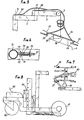
- Fig. 1 is a general view of the device according to the invention.
- Fig. 2 shows a type of attachment of the bracket of FIG. 1.
- Fig. 3 shows a particular method of attachment.
- Fig. 4 schematically shows possibilities of distribution of the articulated arm of FIG. 1.
- Fig. 5 schematically shows the operating principle.
- Fig. 6 shows a detail of the locking system.
- Fig. 7 shows a carriage specially designed for the apparatus of the invention.
- Fig. 8 shows from the front the carriage of FIG. 7.
- Fig. 9 shows a variant of the carriage of FIG. 7.
- Fig. 10 shows a bracket for the carriage of FIG. 9.
- Fig. 11 shows a section through a tube of the stem of FIG. 10.
- Fig. 12 shows the advantageous positions of the distributor arm of FIG. 9.
- Fig. 13 shows an example of leveling.
- Fig. 14 shows a wheel of the carriage of FIG. 9.
- the gripping device 4 can be chosen in various techniques: one can for example provide a mechanical clamp advantageously clamping the edge at the ends. One of the clamping arms will be calculated from the thickness of the joint which will give the regularity of these joints by abutment during installation.
- the gripping device can equally well be automatic, for example by opening and closing control by jacks, or by using a suction cup system.
- a vibrator can be attached to this clamp and vibrate the edge at the time of installation.
- the elevation system 5 can advantageously be a small electric winch mounted at the end of the distributor arm 3.
- the control 7 is advantageously placed on the clamp 4 which allows the operator to properly direct the clamp with his hands while he control with his thumb the descent switch for installation or ascent to remove the edge.
- the distribution system will be a bracket advantageously attached to the fork of the carrier.
- This bracket can be a simple vertical mast surmounted by a pivoting horizontal arrow.
- this arrow will preferably have two joints in the manner of a human arm to obtain better scanning.
- the joints 22 and 23 of the manipulator arm can be alternately free, braked or blocked for horizontal movement security.
- the device controls will preferably be placed on the clamp.
- the manipulator arm can be actuated in the same way, in the horizontal plane, automatically using jacks or either hydraulic or electric motors.
- the axis of the motors will be the axis of rotation.
- the controls may preferably be located on the clamp.
- the stem should preferably be fixed removably on the cross members of the fork.
- Fig. 2 shows one of the fixing means.
- an advantageous way is to provide the side opposite the forks, behind the horizontal bars, with a universal fixing device making it possible to receive an intermediate fixing between the carrier and the equipment.
- the mast of the stem can very well be telescopic, the telescoping being able to be there only for mechanical height adjustments or it will be part of the lifting system. Indeed, it suffices to provide one of the tubes with a seal and a plunger which will rest on the bottom of the other tube and provide for hydraulic injection to obtain a single-acting cylinder for the rise, while by compressing a spring which will control the descent:
- the carriers can be very diverse and will give rise specific arrangements.
- the distribution bracket with its controls provided with its elevation and its grip.
- this stem does not have to be permanently mounted, it will preferably be fixed removably on the fork support deck.
- the carrier is a motorized vehicle, it will advantageously provide electrical or hydraulic force.
- An advantageous way is to create an interchangeable intermediate connection part which will have, on the side of the deck, the standard fixing and, on the side of the shovel, the specific fixing for the machine.
- the same working system can be used for other materials to be laid coming from a pallet such as for example self-blocking pavers previously arranged in the order of laying or not on the pallet.
- a gripping device made up of the number of suitable pliers will be able to place up to 1 m2 per operation.
- the operator guiding this device thanks to the commands which are directly linked, will be able to execute the installation with the desired precision.
- This seat can be fixed either on the device itself, for example on the horizontal apron, or on the carrier (fig. 8).
- Another particularly safe, simple and mechanical device consists in providing the gripping pliers with two guide handles, each equipped with a handbrake or bicycle motorbike clamping handle.
- the axes of rotation of the two distributor arms will be provided with the equivalent of toothed pinions and a ratchet, kept permanently engaged under the effect of a spring.
- the locking pawl is connected to the handlebar handle by a sheathed cable.
- the drum braking systems or known and used discs under the same conditions.
- the assembly can only be operated under the effect of handles, acting on the cable itself unlocking the pinion. As soon as the operator releases the handle (s), the assembly remains absolutely secure, and instantly. All these controls can be combined into a single removable support, hence the interchangeability of the clamps.
- Another problem is to be solved, in particular that of the low loads transportable by certain chargers; this case is advantageously resolved by fixing for example two wheels at the ends of the deck. These wheels will go up or down depending on whether you load or transport. These movements can be produced mechanically, hydraulically or electrically. The load will weigh directly on these wheels and is no longer carried by the machine but pushed or pulled, and the machine will serve as a counterweight. At the same time, these side wheels will serve as stabilizers when maneuvering the distribution.
- FIG. 1 shows a bracket 1 fixed removably by the fasteners 9, surmounted by arms 2 and 3 articulated at 22 and 23 with a small winch 5 electrically connected to a battery 16 and retaining the clamp 4 supporting the controls 6 and 8 of the joints and the winch control 7 5.
- the lifting forks 24 are connected in a manner known per se to the horizontal crosspieces 10 which are themselves connected to two vertical uprights 11 supporting fixing means, in particular holes which are shown, but could be any .
- These connecting means serve to fix a plate or equivalent 13, one side of which supports the standard attachment 12 and the other of which supports the attachments 14 and 15 specific to the carrier which can be a hydraulic loader as well as a hydraulic shovel.
- Fig. 2 shows a type of attachment 9 of the stem which can be positioned vertically by means of the clamp 19 and fixed to the cross members 17 of the fork by clamps.
- Fig. 3 shows an attachment method in which the receiving part 18 is attached to a loading bucket 20 and is housed in the standard attachments 12.
- a crosspiece 17 will serve as a stop for the teeth 21.
- Fig. 4 schematically shows the possibilities of distribution of the articulated arm which can place up to four edges without moving the carrier.
- Fig. 5 schematically shows the operating principle.
- the clamp 4 is removably attached 29 to a kind of handlebar 36 supporting, on the one hand, the control handle 25 controlling the locking system 30 and 31 located on the arm 3 via a sheathed cable 26, on the other hand, the handle 27 controlling under the same conditions the axis of the beam 2.
- This same handlebar supports the control 2 of the winch 5 and the control 28 controlling for example the forward / reverse travel of the carrier.
- Fig. 6 shows the detail of the blocking system in which 33 is the traction cable, 32 are perforated guides, 30 is an axis provided with a shoulder 36 and terminates in a point 35 which engages on a pinion 31 fixed on the rotation axis.
- Spring 34 will hold permanent locking.
- Fig. 7 shows a trolley specially designed for this purpose capable of instantly receiving the fork-stem assembly.
- two electric motors can drive the two front wheels 37 and 38, the blocking of one or the other wheel providing total maneuverability.
- the driver's seat 39 can also be reduced on the installation side.
- All the functions can be either hydraulic or electric and be ensured by generator or batteries.
- This same seat can even be swiveled on the horizontal plane, either freely or motorized which will always give the right position in relation to work.
- Fig. 8 shows from the front the machine of FIG. 7 in which 41 is an axial motor, 42 of the free wheels and 43 the fork lifting system.
- rolling means will be arranged, for example two wheels integral with the assembly, opposite side, that is to say at the tip of the fork, means for guiding the ground will be fitted: casters, skis, etc.
- This assembly is capable of being brought to vacuum under the pallet, the fork ends protruding from the other side.
- a rolling means will be detachably attached to the tip of the forks, wheels or tracks. Just raise the forks appropriately and the whole assembly is capable of being moved, towed if you want, or autonomous by motorization.
- the two floating freewheels can be joined, become self-propelled and the other two wheels will be free.
- the bracket can be changed position and in particular can also be placed on one of the arms of the carrying carriage, preferably near one of the wheels of the arm, this which will make the stem work above the opposite wheel.
- the particular position of the distributing bracket on the advanced part of the machine described gives the shortest jib to lay the edge very close to the machine and the blocks in front. Given the short arms, it is possible, if desired, to remove the mechanically controlled rotation and replace it with a free rotation possibly provided with a brake.
- This particular position can be obtained on a traditional pallet conveyor by a third fork at the end of which the stem will have been mounted. It will be hung on the crosspieces parallel to the other two forks. It will be enough to bring the hydraulics of the machine and the electricity of the battery for the control of the solenoid valves (fig. 10).
- the improvement of the installation will be obtained by using guide marks 52 to position the machine at each translation.
- a mechanical marker 52 designating the end of the previous border will notify the operator that he has traveled the desired distance.
- More complicated systems, by photocell, will even be able to automatically stop the machine at the chosen point or simultaneously control the folding of the arm, etc.
- the operator's task will also be facilitated if a machine position corresponds to jib positions putting it exactly in the laying direction.
- a technical and especially financial improvement for the vertical movement can be obtained by incorporating a hydraulic cylinder in the telescopic tube of the arm.
- the piston of this cylinder will be fitted with a pulley.
- a cable, one end of which will be fixed to the tube, will pass over this pulley and will come out opposite the tube on a return pulley bringing the cable to the gripper.
- the deployment of the cylinder will cause a double stroke of the length of the piston.
- the border installer has two other problems to solve: going straight and making curves with as little as possible to touch up with the direction of his craft.
- One of the simple and inexpensive means is to arrange a compass 87 and a reference mark 88 between the direction 86 and the machine 51. By simple coincidence of the reference mark and the angle chosen, the desired direction is obtained which is maintained by appropriate blocking of the steering. The driver only has to order the start up to the next marker without worrying about the direction.
- the device By its construction the device will already be high ground clearance. In cases of uneven ground it may be advantageous or necessary to correct the levels around the longitudinal axis or the transverse axis.
- the wheels can therefore be height adjustable.
- Fig. 9 shows the carriage 51 positioned by its guide 52 at the end of the raised edge 55 and shows in dotted lines the position of the arm 53 directed at 90 ° to position itself with the edge 54 to be placed directly above the laying point.
- the drawbar 86 is adjusted with respect to directional marks and any blocking device makes it possible to maintain this direction.
- Fig. 10 shows a bracket 57 fixed on a fork 56 adaptable to carriers.
- the bracket is composed of two tubes 59 and 60 made telescopic by a jack 58. It suffices to connect to the carrier machine hydraulically and or electrically.
- Fig. 11 shows a section of the tube 60 in which is hidden the vertical elevation system obtained by a hydraulic jack 71 (or electric) terminated by a deflection pulley 73 of a cable 74 fixed to the tube 72.
- the cable exits by a pulley 75.
- Fig. 12 shows the advantageous positions of the distributor arm at 66 for the edges placed laterally, at 67 and 68 the paver positions in front pose.
- an arm 62 fixed on the lifting part 61 controlled by the jack 69.
- This arm supports at its end an oscillating device 64 for leveling concrete held on silent blocks 63. Oscillation can be obtained by a vibrator 65 or any other means.
- Fig. 13 shows an example of leveling by the arm 62, the silent-blocks 63 the rake 64 with its teeth 79 and a system of visual guidance on the twine by mirror 80.
- Fig. 14 shows a wheel which can be adjusted in height mechanically tor by pin through the holes 89 and 90 on the telescopic tubes 82 and the tube 81 fixed on the frame 83.
- a hydraulic cylinder placed between the two tubes, injected at 84 and controlled at 85, this movement will be instantaneous.
- Other technical means may give the same result.
- Transport from one site to another can be easily resolved by providing the machine with two retractable or removable transport wheels during work and with a drawbar that may be removable. Once raised on at least two wheels and the drawbar attached, it will be purely and simply a trailer like any other.
Landscapes
- Engineering & Computer Science (AREA)
- Structural Engineering (AREA)
- Civil Engineering (AREA)
- Transportation (AREA)
- Architecture (AREA)
- Life Sciences & Earth Sciences (AREA)
- Geology (AREA)
- Mechanical Engineering (AREA)
- Forklifts And Lifting Vehicles (AREA)
- Road Paving Machines (AREA)
Abstract
Description
- La pose de bordures de trottoir est une opération longue et fatigante. De nombreux appareils ont déjà été créés à cet effet. Les outils à mains ne reprennent qu'une partie de l'opération. Les grandes machines conçues spécialement à cet effet sont trop chères pour être à la portée de toutes les entreprises.
- La présente invention a pour objet de diminuer et même de supprimer totalement les fatigues en créant un appareil adaptable de manière amovible totale ou partielle sur les engins roulants, de Travaux Publics entre autres, et qui reprend la palette, la transporte le long du tracé de pose, permet de prélever les bordures une à une et de les mettre en place bout à bout avec la précision et la rapidité requises. Cet objectif est obtenu en associant à différents porteurs des fourches, un dispositif d'élévation et de répartition, un dispositif de préhension et les commandes situées de préférence sur ce dispositif de préhension.
- Conformément à l'invention, l'appareil de pose de bordures de trottoirs ou pavés est caractérisé en ce que des fourches de transport de palettes sont associées à un dispositif d'élévation monté sur des appareils de distribution horizontale orientable et à un organe de préhension muni de commande pour l'opérateur de pose placé sur un même engin porteur.
- Diverses autres caractéristiques de l'invention ressortent d'ailleurs de la description détaillée qui suit.
- Des formes de réalisation de l'objet de l'invention sont représentées, à titre d'exemples non limitatifs, aux dessins annexés.
- La fig. 1 est une vue générale de l'appareil conforme à l'invention.
- La fig. 2 montre un type d'attache de la potence de la fig. 1.
- La fig. 3 montre un mode de fixation particulier.
- La fig. 4 montre schématiquement des possibilités de distribution du bras articulé de la fig. 1.
- La fig. 5 montre schématiquement le principe de fonctionnement.
- La fig. 6 montre un détail du système de blocage.
- La fig. 7 montre un chariot spécialement conçu pour l'appareil de l'invention.
- La fig. 8 montre de face le chariot de la fig. 7.
- La fig. 9 montre une variante du chariot de la fig. 7.
- La fig. 10 montre une potence pour le chariot de la fig. 9.
- La fig. 11 montre une coupe d'un tube de la potence de la fig. 10.
- La fig. 12 montre les positions avantageuses du bras distributeur de la fig. 9.
- La fig. 13 montre un exemple de nivellement.
- La fig. 14 montre une roue du chariot de la fig. 9.
- Le dispositif de préhension 4 peut être choisi dans diverses techniques : on peut par exemple prévoir une pince mécanique serrant avantageusement la bordure aux extrémités. L'un des bras de serrage sera calculé de l'épaisseur du joint ce qui donnera la régularité de ces joints par butée lors de la mise en place.
- Le dispositif de préhension peut tout aussi bien être automatique, par exemple par commande d'ouverture et fermeture par vérins, soit en utilisant un système à ventouse. Un vibrateur peut être fixé sur cette pince et vibrer la bordure au moment de la pose.
- Le système d'élévation 5 peut être avantageusement un petit treuil électrique monté en extrémité du bras distributeur 3. La commande 7 est avantageusement placée sur la pince 4 ce qui permet à l'opérateur de diriger convenablement la pince avec ses mains pendant qu'il commande avec son pouce l'interrupteur de la descente pour la pose ou la montée pour prélever la bordure.
- D'autres systèmes d'élévation sont envisageables avec les moyens hydrauliques ou électriques connus.
- Le système de distribution sera une potence avantageusement fixée à la fourche du porteur. Cette potence peut être un simple mât vertical surmonté d'une flèche horizontale pivotante. Pour des raisons pratiques, cette flèche présentera de préférence deux articulations à la manière d'un bras humain pour obtenir un meilleur balayage. Les articulations 22 et 23 du bras manipulateur peuvent être alternativement libres, freinées ou bloquées pour la sécurité horizontale des mouvements. Les commandes des dispositifs seront placées de préférence sur la pince.
- Le bras manipulateur peut être au même titre actionné, dans le plan horizontal, automatiquement à l'aide de vérins ou de moteurs soit hydrauliques soit électriques. L'axe des moteurs sera l'axe de rotation.
- Les commandes pourront comme précédemment être situées de préférence sur la pince.
- Sur des engins déjà munis de fourche d'origine, on fixera la potence de préférence de manière amovible sur les traverses de la fourche. La fig. 2 montre l'un des moyens de fixation.
- Pour des engins non munis de fourches, une manière avantageuse est de munir le côté opposé aux fourches, derrière les barres horizontales, d'un dispositif universel de fixation permettant de recevoir une fixation intermédiaire entre le porteur et l'appareillage.
- Le mât de la potence peut très bien être télescopique, le télescopage pouvant n'être là que pour des réglages mécaniques de hauteur ou encore il fera partie du système d'élévation. En effet, il suffit de munir l'un des tubes d'un joint et d'un piston plongeur qui prendra appui dans le fond de l'autre tube et prévoir l'injection hydraulique pour obtenir un vérin simple effet pour la montée, tout en comprimant un ressort qui commandera la descente:
- Les porteurs peuvent être très divers et donneront lieu aux aménagements spécifiques.
- Ainsi dans le cas le plus simple, si l'entreprise dispose déjà d'un chariot-élévateur, il suffit d'adjoindre la potence de distribution avec ses commandes munie de son élévation et de sa préhension. Comme cette potence n'a pas à être montée en permanence, elle sera fixée de préférence de manière amovible sur le tablier support des fourches.
- Selon l'élévation choisie, si le porteur est un engin motorisé, il fournira avantageusement la force électrique ou hydraulique.
- Dans le cas où ce sont des chargeurs qui sont disponibles, on assemblera comme déjà dit la potence sur le tablier horizontal support de fourches. Du côté opposé aux fourches seront fixés deux montants verticaux munis de trous ou crochets ou autres moyens de fixation dont la fixation correspondante a été aménagée sur le godet. Cela devient donc un équipement complémentaire de ce godet, on pourrait naturellement mettre aussi cet équipement à la place du godet lui-même.
- Si l'on veut faire faire ce même travail par une pelle hydraulique, on enlèvera le godet et on aménagera les points de fixation correspondants derrière le tablier de la fourche. Une manière avantageuse est de créer une pièce de connexion intermédiaire interchangeable qui aura, du côté du tablier, la fixation standard et, du côté de la pelle, les fixations spécifiques à l'engin.
- Un autre cas est envisageable, celui de la création d'un petit appareil spécifique, bon marché, tracté par le personnel ou d'autres engins ou de préférence auto-moteur. Les explications des fig. 7 et 8 précisent le fonctionnement.
- Le même système de travail peut être utilisé pour d'autres matériaux à poser provenant d'une palette tels que par exemple des pavés autobloquants préalablement disposés dans l'ordre de pose ou non sur la palette. Un dispositif de préhension formé du nombre de pinces appropriées sera en mesure de poser jusqu'à 1 m2 par opération. L'opérateur guidant ce dispositif, grâce aux commandes qui sont directement reliées, pourra exécuter la pose avec la précision voulue.
- A l'inverse, il est envisageable de ramasser et de palettiser des objets divers sous réserve d'avoir les pinces correspondantes.
- Pour faire travailler le conducteur dans les meilleures conditions physiques possible, il est avantageux de lui prévoir un siège aussi près que possible le long des bordures. Ce siège pourra être fixé soit sur l'appareil lui-même par exemple sur le tablier horizontal, soit sur le porteur (fig. 8).
- Un autre dispositif particulièrement sûr, simple et mécanique, donné à titre indicatif non limitatif, consiste à munir la pince à préhension de deux poignées de guidage , chacune équipée de poignée de serrage type frein à main de vélo ou moto. Les axes de rotation des deux bras distributeurs seront munis de l'équivalent de pignons crantés et d'un cliquet, maintenu enclenché en permanence sous l'effet d'un ressort. Le cliquet d'enclenchement est relié à la poignée du guidon par un câble sous gaine. Au lieu du cliquet et du pignon, on peut utiliser aussi les systèmes de freinage à tambour ou disques connus et utilisés dans les mêmes conditions.
- L'ensemble ne pourra être manoeuvré que sous l'effet de poignées, agissant sur le câble lui-même déverrouillant le pignon. Dès que l'opérateur lâche la ou les poignées, l'ensemble reste bloqué de manière absolument sûre, et instantanément. Toutes ces commandes peuvent être réunies en un seul support amovible d'où l'interchangeabilité des pinces.
- Un autre problème est à résoudre, notamment celui des faibles charges transportables par certains chargeurs; ce cas est avantageusement résolu en fixant par exemple deux roues aux extrémités du tablier. Ces roues monteront ou s'abaisseront selon que l'on charge ou transporte. Ces mouvements pourront être produits mécaniquement, hydrauliquement ou électriquement. La charge pèsera directement sur ces roues et n'est plus portée par l'engin mais poussée ou tirée, et l'engin servira de contrepoids. En même temps, ces roues latérales serviront de stabilisateurs lors de la manoeuvre de la distribution.
- En se référant plus particulièrement aux dessins, la fig. 1 montre une potence 1 fixée de manière amovible par les fixations 9, surmontée de bras 2 et 3 articulée en 22 et 23 avec un petit treuil 5 relié électriquement à une batterie 16 et retenant la pince 4 supportant les commandes 6 et 8 des articulations et la commande 7 du treuil 5. Les fourches élévatrices 24 sont reliées de manière connue en soi aux traverses horizontales 10 qui sont elles-mêmes reliées à deux montants verticaux 11 supportant des moyens de fixation, notamment des trous qui sont représentés, mais pourraient être quelconques. Ces moyens de liaison servent à fixer une plaque ou équivalent 13 dont un côté supporte la fixation standard 12 et dont l'autre supporte les fixations 14 et 15 spécifiques à l'engin porteur qui peut aussi bien être un chargeur hydraulique qu'une pelle hydraulique.
- La fig. 2 montre un type d'attache 9 de la potence po- sitionnable en hauteur par l'intermédiaire du serrage 19 et fixé sur les traverses 17 de la fourche par des serrages.
- La fig. 3 montre un mode de fixation où la partie réceptrice 18 est fixée sur un godet chargeur 20 et vient se loger dans les fixations standard 12. Une traverse 17 servira de butée aux dents 21.
- La fig. 4 montre, schématiquement les possibilités de distribution du bras articulé pouvant poser jusqu'à quatre bordures sans déplacer l'engin porteur.
- La fig. 5 montre schématiquement le principe de fonctionnement. La pince 4 est fixée de manière amovible 29 à un genre de guidon 36 supportant, d'une part, la poignée de commande 25 commandant le système de blocage 30 et 31 situé sur le bras 3 par l'intermédiaire d'un câble sous gaine 26, d'autre part, la poignée 27 commandant dans les mêmes conditions l'axe de la poutre 2. Ce même guidon supporte la commande 2 du treuil 5 et la commande 28 commandant par exemple la marche AV/AR du porteur.
- La fig. 6 montre le détail du système de blocage dans lequel 33 est le câble de traction, 32 sont des guides perforés, 30 est un axe muni d'un épaulement 36 et terminé en pointe 35 venant s'enclencher sur un pignon 31 fixé sur l'axe de rotation. Le ressort 34 maintiendra le verrouillage permanent.
- La fig. 7 montre un chariot spécialement conçu à cet effet capable de recevoir instantanément l'ensemble fourche-potence. A titre d'exemple deux moteurs électriques peuvent assurer l'entraînement des deux roues avant 37 et 38, le blocage de l'une ou l'autre roue apportant une manoeuvrabilité totale.
- Sachant que la pose se fait latéralement, le siège conducteur 39 peut être également amenégé du côté pose.
- Toutes les fonctions pourront être ou hydrauliques ou électriques et être assurées par groupe électrogène ou par batteries.
- Compte tenu de la position du siège du conducteur,de l'emplacement des commandes sur le guidon, il sera possible d'effectuer le travail complet en position assise.
- Ce même siège peut même être pivotant sur le plan horizontal, soit de manière libre, soit de manière motorisée ce qui donnera toujours la bonne position par rapport au travail.
- La fig. 8 montre de face l'engin de la fig. 7 dans lequel 41 est un moteur axial, 42 des roues libres et 43 le système d'élévation de la fourche. En supprimant la motorisation, il est naturellement possible d'obtenir un engin tracté par un autre engin ou manuellement.
- Une autre manière avantageuse de réaliser l'invention est de prévoir que l'appareil fourche plus potence devient partie de porteur. Par exemple, côté fourche on aménagera des moyens de roulage, par exemple deux roues solidaires de l'ensemble, côté opposé, c'est-à-dire en extrémité pointe de fourche on aménagera des moyens de guidage au sol : roulettes, skis, etc .. Cet ensemble est capable d'être amené à vide sous la palette, les extrémités de fourche dépassant de l'autre côté.
- Pour transporter la charge, un moyen de roulage sera fixé de manière amovible à la pointe des fourches, roues ou chenillettes. Il suffit de relever les fourches de manière appropriée et tout l'ensemble est capable d'être déplacé, tracté si l'on veut,ou autonome par motorisation.
- A la fig. 8, les deux roues libres flottantes peuvent être réunies, devenir automotrices directrices et les deux autres roues seront libres. Selon le type de pose que l'on fait, frontal ou latéral, la potence pourra être changée de position et notamment être placée aussi sur l'un des bras du chariot porteur,de préférence près de l'une des roues du bras,ce qui fera travailler la potence au-dessus de la roue opposée.
- Selon l'invention, et notamment dans la réalisation des fig. 9 à 14, la position particulière de la potence distributrice sur la partie avancée de la machine décrite donne la flèche la plus courte pour poser en latéral la bordure très près de la machine et les pavés en frontal. Compte tenu des bras courts on peut, si l'on veut, supprimer la rotation commandée mécaniquement et la remplacer par une rotation libre éventuellement munie d'un frein.
- Cette position particulière peut être obtenue sur un transporteur à palettes traditionnel par une troisième fourche au bout de laquelle aura été montée la potence. Elle sera accrochée sur les traverses parallèlement aux deux autres fourches. Il suffira d'amener l'hydraulique de l'engin et l'électricité de la batterie pour la commande des électrovannes (fig. 10).
- L'amélioration de la pose s'obtiendra en utilisant des repères de guidage 52 pour positionner la machine à chaque translation. A titre d'exemple, un repère mécanique 52 désignant la fin de la bordure précédente préviendra l'opérateur qu'il a parcouru la distance voulue. Des systèmes plus compliqués, par cellule photoélectrique,pourront même arrêter automatiquement la machine au point choisi ou commander simultanément le repli du bras, etc ... La tâche de l'opérateur sera également facilitée si à une position de machine correspondent des positions de potence mettant celle-ci exactement dans la direction de pose. Exemple : une butée de 90° du bras mettant celui-ci en direction de pose. Il ne reste plus qu'à commander l'extension du bras jusqu'à la ficelle et la pose par la descente verticale.
- Une amélioration technique et surtout financière pour le mouvement vertical pourra être obtenue en incorporant dans le tube télescopique du bras un vérin hydraulique. Le piston de ce vérin sera muni d'une poulie. Un câble dont l'une des extrémités sera fixée sur le tube passera sur cette poulie et ressortira à l'opposé du tube sur une poulie de renvoi amenant le câble jusqu'à la pince de préhension. Le déploiement du vérin provoquera une course double de la longueur du piston.
- Le poseur de bordures a encore deux autres problèmes à résoudre : aller droit et faire des courbes en ayant aussi peu que possible à retoucher à la direction de son engin. L'un des moyens simples et peu onéreux est d'aménager un compas 87 et un repère 88 entre la direction 86 et la machine 51. Par simple coïncidence du repère et de l'angle choisi on obtient la direction voulue que l'on maintient par blocage approprié de la direction. Le conducteur n'a qu'à commander la mise en route jusqu'au prochain repère sans se soucier de la direction.
- D'autres moyens plus compliqués peuvent être imaginés corrigeant même automatiquement la trajectoire.
- Le réglage du béton de pose est jusqu'ici fait manuellement par un homme. Cette opération pourrait également être confiée à la machine avec assez de précision.
- Il suffirait par exemple de prévoir un bras 62 fixé sur le système élévateur de la fourche 61. Ce bras arriverait au-dessus du mortier, serait muni par exemple d'un peigne rateau vibrant et d'une lame niveleuse. On pourra se régler en épaisseur en se repèrant sur la ficelle avec un dispositif approprié, mécanique, optique ou sur un rayon laser. Toutes les corrections de niveau se feront avec le vérin d'élévation de palette. Un système de lecture optique ou autre facilitera le réglage en se repèrant sur la ficelle sans y toucher.
- De par sa construction l'appareil sera déjà haut de garde au sol. Dans les cas de sol inégal il peut être avantageux ou nécessaire de corriger les niveaux autour de l'axe longitudinal ou l'axe transversal. Les roues peuvent donc être à hauteur réglable.
- La fig. 9 montre le chariot 51 positionné par son guide 52 au bout de la bordure 55 posée et montre en pointillés la position du bras 53 dirigé à 90° pour se positionner avec la bordure 54 à poser directement au-dessus du point de pose. Le timon 86 est réglé par rapport à des repères directionnels et un dispositif de blocage quelconque permet de maintenir cette direction.
- La fig. 10 montre une potence 57 fixée sur une fourche 56 adaptable sur des porteurs.
- La potence est composée de deux tubes 59 et 60 rendus télescopiques par un vérin 58. Il suffit de raccorder sur l'engin porteur hydrauliquement et ou électriquement.
- La fig. 11 montre une coupe du tube 60 dans lequel est caché le système d'élévation vertical obtenu par un vérin hydraulique 71 (ou électrique) terminé par une poulie de renvoi 73 d'un câble 74 fixé sur le tube 72. Le câble sort par une poulie 75.
- La fig. 12 montre les positions avantageuses du bras distributeur en 66 pour les bordures posées en latéral, en 67 et 68 les positions de pavés en pose frontale. En vue en plan il est montré un bras 62 fixé sur la partie élévatrice 61 commandée par le vérin 69. Ce bras supporte à son extrémité un dispositif oscillant 64 de nivellement de béton maintenu sur des silent-blocs 63. L'oscillation peut être obtenue par un vibreur 65 ou tout autre moyen.
- La fig. 13 montre un exemple de nivellement par le bras 62, les silent-blocs 63 le rateau 64 avec ses dents 79 et un système de guidage visuel sur la ficelle par miroir 80.
- La fig. 14 montre une roue qui peut être réglée en hauteur mécaniquement par goupille par les trous 89 et 90 sur les tubes télescopiques 82 et le tube 81 fixé sur le châssis 83. Par un vérin hydraulique placé entre les deux tubes, injecté en 84 et commandé en 85, ce mouvement sera instantané. D'autres moyens techniques pourront donner le même résultat.
- Le transport d'un chantier à un autre peut se résoudre aisément en munissant la machine de deux roues de transport rétractables ou amovibles pendant le travail et d'un timon éventuellement amovible. Une fois relevée sur ses deux roues au moins et le timon attaché, ce sera purement et simplement une remorque comme une autre.
Claims (20)
Applications Claiming Priority (4)
| Application Number | Priority Date | Filing Date | Title |
|---|---|---|---|
| FR8501035A FR2576619B1 (fr) | 1985-01-25 | 1985-01-25 | Appareillage de pose de bordures, paves autobloquants ou autre. |
| FR8501035 | 1985-01-25 | ||
| FR8509459 | 1985-06-21 | ||
| FR8509459A FR2583798B2 (fr) | 1985-06-21 | 1985-06-21 | Appareillage de pose de bordures, paves autobloquants ou autre. |
Publications (3)
| Publication Number | Publication Date |
|---|---|
| EP0189356A2 true EP0189356A2 (fr) | 1986-07-30 |
| EP0189356A3 EP0189356A3 (en) | 1987-07-08 |
| EP0189356B1 EP0189356B1 (fr) | 1992-10-21 |
Family
ID=26224347
Family Applications (1)
| Application Number | Title | Priority Date | Filing Date |
|---|---|---|---|
| EP86400150A Expired - Lifetime EP0189356B1 (fr) | 1985-01-25 | 1986-01-24 | Appareil de pose de bordures, pavés autobloquants ou autre |
Country Status (3)
| Country | Link |
|---|---|
| US (1) | US4740102A (fr) |
| EP (1) | EP0189356B1 (fr) |
| DE (1) | DE3686977T2 (fr) |
Cited By (7)
| Publication number | Priority date | Publication date | Assignee | Title |
|---|---|---|---|---|
| FR2593201A1 (fr) * | 1986-01-20 | 1987-07-24 | Acodim Sarl | Machine a poser des bordures de trottoir |
| FR2604735A1 (fr) * | 1986-10-02 | 1988-04-08 | Martin Entreprise Ch | Chargeur pour la pose de bordures de trottoirs |
| GB2287012A (en) * | 1994-03-05 | 1995-09-06 | Johnson Peter A | Slab laying |
| WO2015044186A1 (fr) * | 2013-09-25 | 2015-04-02 | Keith Annett | Appareil d'élévation automoteur pour élever des dalles de pavage, des bordures de trottoir et des objets lourds similaires |
| GB2537054A (en) * | 2014-09-16 | 2016-10-05 | Annett Keith | Self-propelled lifting apparatus for lifting paving slabs, kerb stones and similar heavy objects |
| EP4079675A1 (fr) * | 2021-04-20 | 2022-10-26 | J. Schmalz GmbH | Dispositif de manutention à configuration de repos définie |
| CN117361324A (zh) * | 2023-10-29 | 2024-01-09 | 太仓优盛电子有限公司 | 一种绝缘漆浸渍设备用升降装置 |
Families Citing this family (6)
| Publication number | Priority date | Publication date | Assignee | Title |
|---|---|---|---|---|
| DE4327663C2 (de) * | 1993-08-17 | 1998-07-02 | Probst Greiftechnik Verlegesys | Vakuum-Hebeeinrichtung für Steinelemente |
| US6135704A (en) * | 1997-11-04 | 2000-10-24 | Cascade Corporation | Layer-picking clamp supported on a forklift truck |
| DE20004153U1 (de) * | 2000-03-08 | 2000-06-29 | Kommanditgesellschaft EMS Gleisbau GmbH & Co., 21217 Seevetal | Bahnsteigkantensetzvorrichtung |
| GB2400595A (en) * | 2003-04-15 | 2004-10-20 | Alan Goodwin | Kerbstone and beany block mechanical lifter on moving platform |
| NL1027169C2 (nl) * | 2004-10-04 | 2006-04-06 | Martens En Van Oord Groep B V | Semi-permanente rijbaan. |
| JP7101607B2 (ja) * | 2018-12-20 | 2022-07-15 | 鹿島建設株式会社 | 作業装置 |
Family Cites Families (23)
| Publication number | Priority date | Publication date | Assignee | Title |
|---|---|---|---|---|
| US637644A (en) * | 1893-12-30 | 1899-11-21 | Climax Road Machine Company | Road machine or scraper. |
| US2364493A (en) * | 1943-02-17 | 1944-12-05 | Yale & Towne Mfg Co | Crane platform |
| US2580045A (en) * | 1948-01-12 | 1951-12-25 | Ancil O Reed | Stepladder |
| US2581568A (en) * | 1948-06-18 | 1952-01-08 | Cecil C Wooley | Apparatus for handling concrete blocks |
| US2934035A (en) * | 1958-09-29 | 1960-04-26 | James O Hardy | Steering indicator |
| US3312361A (en) * | 1965-05-06 | 1967-04-04 | William E Foster | Converter unit |
| US3415339A (en) * | 1967-04-18 | 1968-12-10 | Clyde M. Range | Fork lift attachment |
| US3741083A (en) * | 1970-08-26 | 1973-06-26 | V Shakhlin | Compaction device for loose materials or concrete |
| US3851777A (en) * | 1972-06-13 | 1974-12-03 | M Dilny | Adjustable boom attachment |
| DE2335157A1 (de) * | 1973-07-11 | 1975-01-30 | Bautechnologie Forsch | Vorrichtung zum verlegen von pflastersteinen |
| DE2426713A1 (de) * | 1974-06-01 | 1975-12-11 | Bautechnologie Forsch | Verlegegeraet fuer platten |
| DE2715476A1 (de) * | 1977-04-06 | 1978-10-19 | Barth Kg Dr | Verfahren und vorrichtung zum herstellen eines bodenbelags aus einzelnen pflastersteinen |
| US4168130A (en) * | 1977-04-22 | 1979-09-18 | Dr. Barth Kg | Apparatus for placing paving elements |
| EP0132442A1 (fr) * | 1977-08-31 | 1985-02-13 | Hans-Theodor Grisebach | Appareil de positionnement à entraînement par broche |
| DE2756440A1 (de) * | 1977-12-17 | 1979-06-21 | Oldenburger Betonsteinwerke | Vorrichtung zum verlegen von pflasterstein-verlegeeinheiten |
| FR2476625A1 (fr) * | 1980-02-22 | 1981-08-28 | Klein Jean | Support de montage d'un engin accessoire de levage sur le tablier d'un chariot elevateur et chariot de mise en oeuvre |
| DE3109723A1 (de) * | 1981-03-13 | 1982-09-23 | Rudolf N. 8034 Germering Aumiller | Beton-pflastereinheiten-schnellverlegeverfahren |
| US4405282A (en) * | 1981-08-27 | 1983-09-20 | Carter Jack D | Load bearing arrangement for a movable bucket fork lift attachment |
| GB2129359A (en) * | 1982-10-26 | 1984-05-16 | John Claude Terrington | Slab lifter |
| DE3323983A1 (de) * | 1983-07-02 | 1985-01-03 | Rekers Betonwerk GmbH & Co KG, 4441 Spelle | Geraet zum verlegen von steinen |
| DE3343991A1 (de) * | 1983-12-06 | 1985-06-20 | Ing. Kurt Schade Formen- + Werkzeugbau, 2878 Wildeshausen | Fahrzeug zum verlegen von pflasterstein-verlegeeinheiten |
| DE3446231A1 (de) * | 1983-12-21 | 1985-07-11 | Franz Grötz GmbH & Co KG Bauunternehmung, 7560 Gaggenau | Vorrichtung zum verlegen von randsteinen o.dgl. |
| DE8419848U1 (de) * | 1984-07-03 | 1985-01-10 | Grötz, Georg, 7563 Loffenau | Vorrichtung zum Verlegen von Randsteinen od. dgl. |
-
1986
- 1986-01-24 US US06/822,269 patent/US4740102A/en not_active Expired - Fee Related
- 1986-01-24 EP EP86400150A patent/EP0189356B1/fr not_active Expired - Lifetime
- 1986-01-24 DE DE8686400150T patent/DE3686977T2/de not_active Expired - Fee Related
Cited By (9)
| Publication number | Priority date | Publication date | Assignee | Title |
|---|---|---|---|---|
| FR2593201A1 (fr) * | 1986-01-20 | 1987-07-24 | Acodim Sarl | Machine a poser des bordures de trottoir |
| FR2604735A1 (fr) * | 1986-10-02 | 1988-04-08 | Martin Entreprise Ch | Chargeur pour la pose de bordures de trottoirs |
| GB2287012A (en) * | 1994-03-05 | 1995-09-06 | Johnson Peter A | Slab laying |
| GB2287012B (en) * | 1994-03-05 | 1998-02-25 | Johnson Peter A | Transport devices |
| WO2015044186A1 (fr) * | 2013-09-25 | 2015-04-02 | Keith Annett | Appareil d'élévation automoteur pour élever des dalles de pavage, des bordures de trottoir et des objets lourds similaires |
| GB2537054A (en) * | 2014-09-16 | 2016-10-05 | Annett Keith | Self-propelled lifting apparatus for lifting paving slabs, kerb stones and similar heavy objects |
| EP4079675A1 (fr) * | 2021-04-20 | 2022-10-26 | J. Schmalz GmbH | Dispositif de manutention à configuration de repos définie |
| US12030730B2 (en) | 2021-04-20 | 2024-07-09 | J. Schmalz Gmbh | Handling device with defined idle configuration |
| CN117361324A (zh) * | 2023-10-29 | 2024-01-09 | 太仓优盛电子有限公司 | 一种绝缘漆浸渍设备用升降装置 |
Also Published As
| Publication number | Publication date |
|---|---|
| US4740102A (en) | 1988-04-26 |
| DE3686977T2 (de) | 1993-06-03 |
| DE3686977D1 (de) | 1992-11-26 |
| EP0189356B1 (fr) | 1992-10-21 |
| EP0189356A3 (en) | 1987-07-08 |
Similar Documents
| Publication | Publication Date | Title |
|---|---|---|
| EP0189356B1 (fr) | Appareil de pose de bordures, pavés autobloquants ou autre | |
| FR2458420A1 (fr) | Tracteur a transmission hydraulique | |
| EP0786201B1 (fr) | Robot taille-haies télécommandé avec réglage automatique des niveaux | |
| EP0755841B1 (fr) | Chariot de manutention | |
| EP0505240B1 (fr) | Installation pour la pose et la substitution d'éléments de construction de voie ferrée et procédé utilisant cette installation | |
| EP0971071A1 (fr) | Procédé et dispositif de pose d'élément de voie par des lorries à chenilles | |
| GB2172249A (en) | Trolley for facilitating movement and or laying of paving slabs or flags | |
| FR2606051A1 (fr) | Engin de travaux publics pour la realisation de tranchees | |
| FR2593201A1 (fr) | Machine a poser des bordures de trottoir | |
| FR2521191A1 (fr) | Engin pour travaux du sol | |
| FR2576619A1 (fr) | Appareillage de pose de bordures, paves autobloquants ou autre. | |
| FR2576618A3 (fr) | Appareillage de pose de bordures, paves autobloquants ou autre. | |
| GB2207412A (en) | Apparatus for lifting and transporting paving slabs or similar objects | |
| FR2533110A1 (fr) | Machine mobile d'eclaircissage de forets | |
| LU81658A1 (fr) | Machine pour la pose de paves ou dalles en beton ou autre materiau | |
| EP0592326B1 (fr) | Appareil pour creuser dans le sol des tranchées de grande profondeur à l'aide de tambours de fraisage | |
| EP2836413B1 (fr) | Véhicule de transport ou porte-outil articule avec conduite au sol | |
| FR2700301A1 (fr) | Chariot pour manipuler les roues. | |
| FR2750411A1 (fr) | Grue de chantier a pivot inferieur comprenant un chariot | |
| FR2597460A1 (fr) | Engin mobile de transport et manutention d'objets, plus particulierement pour cimetiere | |
| EP0951813A1 (fr) | Dispositif de support de machine utilisable notamment en agriculture, arboriculture et viticulture | |
| FR2570571A1 (fr) | Dispositif de commande de tondeuse a gazon | |
| FR2641755A1 (fr) | Appareil tracteur autorisant le travail d'arbustes disposes en haie plate et continue et/ou la recolte de fruits | |
| FR2583795A4 (fr) | Appareillage de pose de bordures, paves autobloquants ou autre. | |
| GB2266699A (en) | Paving or like slab transporter |
Legal Events
| Date | Code | Title | Description |
|---|---|---|---|
| PUAI | Public reference made under article 153(3) epc to a published international application that has entered the european phase |
Free format text: ORIGINAL CODE: 0009012 |
|
| 17P | Request for examination filed |
Effective date: 19860129 |
|
| AK | Designated contracting states |
Kind code of ref document: A2 Designated state(s): DE GB IT NL |
|
| PUAL | Search report despatched |
Free format text: ORIGINAL CODE: 0009013 |
|
| AK | Designated contracting states |
Kind code of ref document: A3 Designated state(s): DE GB IT NL |
|
| 17Q | First examination report despatched |
Effective date: 19881129 |
|
| GRAA | (expected) grant |
Free format text: ORIGINAL CODE: 0009210 |
|
| AK | Designated contracting states |
Kind code of ref document: B1 Designated state(s): DE GB IT NL |
|
| PG25 | Lapsed in a contracting state [announced via postgrant information from national office to epo] |
Ref country code: GB Effective date: 19921021 Ref country code: NL Effective date: 19921021 Ref country code: IT Free format text: LAPSE BECAUSE OF FAILURE TO SUBMIT A TRANSLATION OF THE DESCRIPTION OR TO PAY THE FEE WITHIN THE PRE;WARNING: LAPSES OF ITALIAN PATENTS WITH EFFECTIVE DATE BEFORE 2007 MAY HAVE OCCURRED AT ANY TIME BEFORE 2007. THE CORRECT EFFECTIVE DATE MAY BE DIFFERENT FROM THE ONE RECORDED.SCRIBED TIME-LIMIT Effective date: 19921021 |
|
| REF | Corresponds to: |
Ref document number: 3686977 Country of ref document: DE Date of ref document: 19921126 |
|
| NLV1 | Nl: lapsed or annulled due to failure to fulfill the requirements of art. 29p and 29m of the patents act | ||
| GBV | Gb: ep patent (uk) treated as always having been void in accordance with gb section 77(7)/1977 [no translation filed] |
Effective date: 19921021 |
|
| PLBI | Opposition filed |
Free format text: ORIGINAL CODE: 0009260 |
|
| 26 | Opposition filed |
Opponent name: PROBST, GREIF- UND FOERDERTECHNIK GMBH, Effective date: 19930721 |
|
| PGFP | Annual fee paid to national office [announced via postgrant information from national office to epo] |
Ref country code: DE Payment date: 19950929 Year of fee payment: 10 |
|
| PG25 | Lapsed in a contracting state [announced via postgrant information from national office to epo] |
Ref country code: DE Effective date: 19961001 |
|
| APAC | Appeal dossier modified |
Free format text: ORIGINAL CODE: EPIDOS NOAPO |
|
| APAC | Appeal dossier modified |
Free format text: ORIGINAL CODE: EPIDOS NOAPO |
|
| APCC | Communication from the board of appeal sent |
Free format text: ORIGINAL CODE: EPIDOS OBAPO |
|
| APCC | Communication from the board of appeal sent |
Free format text: ORIGINAL CODE: EPIDOS OBAPO |
|
| APCC | Communication from the board of appeal sent |
Free format text: ORIGINAL CODE: EPIDOS OBAPO |
|
| APCC | Communication from the board of appeal sent |
Free format text: ORIGINAL CODE: EPIDOS OBAPO |
|
| APCC | Communication from the board of appeal sent |
Free format text: ORIGINAL CODE: EPIDOS OBAPO |
|
| APCC | Communication from the board of appeal sent |
Free format text: ORIGINAL CODE: EPIDOS OBAPO |
|
| APCC | Communication from the board of appeal sent |
Free format text: ORIGINAL CODE: EPIDOS OBAPO |
|
| APCC | Communication from the board of appeal sent |
Free format text: ORIGINAL CODE: EPIDOS OBAPO |
|
| APAC | Appeal dossier modified |
Free format text: ORIGINAL CODE: EPIDOS NOAPO |
|
| APCC | Communication from the board of appeal sent |
Free format text: ORIGINAL CODE: EPIDOS OBAPO |
|
| PLAW | Interlocutory decision in opposition |
Free format text: ORIGINAL CODE: EPIDOS IDOP |
|
| PLBL | Opposition procedure terminated |
Free format text: ORIGINAL CODE: EPIDOS OPPC |
|
| PLBM | Termination of opposition procedure: date of legal effect published |
Free format text: ORIGINAL CODE: 0009276 |
|
| STAA | Information on the status of an ep patent application or granted ep patent |
Free format text: STATUS: OPPOSITION PROCEDURE CLOSED |
|
| 27C | Opposition proceedings terminated |
Effective date: 20010728 |
|
| APAH | Appeal reference modified |
Free format text: ORIGINAL CODE: EPIDOSCREFNO |