EP0187902A1 - Gehäuse für ein elektrisches Bauteil - Google Patents
Gehäuse für ein elektrisches Bauteil Download PDFInfo
- Publication number
- EP0187902A1 EP0187902A1 EP85113510A EP85113510A EP0187902A1 EP 0187902 A1 EP0187902 A1 EP 0187902A1 EP 85113510 A EP85113510 A EP 85113510A EP 85113510 A EP85113510 A EP 85113510A EP 0187902 A1 EP0187902 A1 EP 0187902A1
- Authority
- EP
- European Patent Office
- Prior art keywords
- carrier
- protective frame
- guide
- component
- housing
- Prior art date
- Legal status (The legal status is an assumption and is not a legal conclusion. Google has not performed a legal analysis and makes no representation as to the accuracy of the status listed.)
- Granted
Links
- 230000001681 protective effect Effects 0.000 claims abstract description 34
- 238000007789 sealing Methods 0.000 claims description 5
- 229920001187 thermosetting polymer Polymers 0.000 claims description 4
- 229920001169 thermoplastic Polymers 0.000 claims description 2
- 239000004416 thermosoftening plastic Substances 0.000 claims description 2
- 239000000463 material Substances 0.000 claims 1
- 230000008878 coupling Effects 0.000 description 8
- 238000010168 coupling process Methods 0.000 description 8
- 238000005859 coupling reaction Methods 0.000 description 8
- 239000000428 dust Substances 0.000 description 3
- 239000004033 plastic Substances 0.000 description 3
- 238000002347 injection Methods 0.000 description 2
- 239000007924 injection Substances 0.000 description 2
- 238000001746 injection moulding Methods 0.000 description 2
- 238000011161 development Methods 0.000 description 1
- 230000018109 developmental process Effects 0.000 description 1
- 239000013013 elastic material Substances 0.000 description 1
- 238000005538 encapsulation Methods 0.000 description 1
Images
Classifications
-
- H—ELECTRICITY
- H01—ELECTRIC ELEMENTS
- H01F—MAGNETS; INDUCTANCES; TRANSFORMERS; SELECTION OF MATERIALS FOR THEIR MAGNETIC PROPERTIES
- H01F7/00—Magnets
- H01F7/06—Electromagnets; Actuators including electromagnets
Definitions
- the invention relates to a housing for an electrical component, in particular for a coil for electromagnetically actuated valves, according to the preamble of patent claim 1.
- Coils which are provided in particular for electromagnetically actuated valves, can be provided, for example, with a plastic casing serving as a housing to protect them against the ingress of moisture and dust. It is conceivable to design the housing in a pot shape and to close it with a lid serving as a carrier for an electrically conductive plug pin.
- a guide and protective frame can be formed on the side of the carrier facing away from the coil housing. The guiding and protective frame also serves to guide and secure an electrical coupling.
- the carrier for the plug pin can be connected to the housing by means of a screw connection with the interposition of a sealing ring between the cup-shaped housing and the carrier.
- a one-piece design of the housing and the carrier provided with the guide and protective frame is problematic since the housing often consists of a heat-resistant thermoset, but the guide and protective frame must consist of an elastic material in order to prevent an electrical coupling from being inserted incorrectly into the guide - and protective frame or other mechanical loads to prevent breakage of the guide and protective frame.
- the invention is therefore based on the object of improving a housing for an electrical component of the type mentioned in such a way that a simplified structure of the housing and a secure seal of the electrical component is achieved with simple means.
- the invention offers the advantage, in particular, of obtaining a housing for an electrical component with simple means, which is protected from moisture and dirt by the design of the housing and the support for the plug pins as a one-piece structural unit, and by the design of the guide and protective frame to receive an unbreakable receptacle for an electrical coupling as an independent component that can be connected to the housing.
- the guide and protective frame can be exchanged in a simple manner without having to make any changes to the housing or to the carrier for the plug pins. Due to the interchangeability of the guide and protective frame, different electrical couplings can be connected in their dimensions to the electrical component provided with the housing according to the invention.
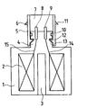
- the illustration shows a housing for a coil with an exchangeable guide and protective frame.
- a coil 2 is shown, which is coated with a plastic mass.
- the plastic mass is preferably a heat-resistant thermosetting plastic and forms the housing 1 of the coil 2.
- a core is arranged centrally in the injection mold, which core is used as a guide tube 3 in the housing after the injection molding around the coil for an anchor serving cylindrical opening.
- the injection mold is designed so that the housing 1 receives a projection which serves as a carrier 4 for two connector pins 8, 9.
- the connector pins 8, 9 and the connecting lines 14, 15 from the coil 2 to the connector pins 8, 9 are simultaneously injected into the carrier 4 during the encapsulation of the coil, so that the connector pins 8, 9 of the carrier 4 and the housing 1 are in one piece Unit forms.
- a recess 13 is provided running in the circumferential direction of the carrier 4. Another groove-like recess running in the circumferential direction of the carrier 4 serves to mount a sealing ring 10.
- a tubular guide and protective frame 5 is pushed onto the carrier 4.
- the guide and protective frame 5 has on its inner wall a circumferential projection 12 which extends onto the lateral surface (wall) of the carrier 4 and which engages in the recess 13 of the carrier 4 and forms a latching connection therewith.
- the guide and protective frame 5 is dimensioned in the direction of its longitudinal axis so that it projects so far beyond the connector pins 8, 9 anchored in the carrier that they are protected against mechanical influences.
- nose-like projections 6, 11 are provided which, when an electrical coupling is pushed onto the guide and protective frame, cooperates with corresponding recesses provided in the coupling housing in the manner of a snap connection.
- the nose-like projections can be dispensed with if the coupling is inserted into the interior 7 of the guide and protective frame 5.
- the sealing ring 10 prevents the ingress of moisture and dust into the interior 7 of the guide and protective frame 5, in which the non-molded part of the connector pins 8, 9 is located.
- a plurality of individual depressions in the lateral surface of the carrier 4 and a plurality of corresponding individual projections can also be provided on the inner wall of the guide and protective frame 5.
- the carrier 4 with an external thread and the guide and protective frame 5 partially with an internal thread, so that the carrier 4, which forms a one-piece structural unit with the housing 1 and represents a first component 4, 1, and the guide and the protective frame 5, which represents a second component 5, can be screwed together by screwing the guide and protective frame 5 onto the projection of the housing 1 serving as a carrier 4 for the plug pins 8, 9.
- the housing 1 is preferably made of a thermoset and the guide and protective frame is preferably made of a thermoplastic.
Landscapes
- Physics & Mathematics (AREA)
- Electromagnetism (AREA)
- Engineering & Computer Science (AREA)
- Power Engineering (AREA)
- Connector Housings Or Holding Contact Members (AREA)
Abstract
Description
- Die Erfindung betrifft ein Gehäuse für ein elektrisches Bauteil, insbesondere für eine Spule für elektromagnetisch betätigbare Ventile, gemäß dem Oberbegriff des Patentanspruchs 1.
- Spulen, die insbesondere für elektromagnetisch betätigbare Ventile vorgesehen sind, können zum Schutz gegen das Eindringen von Feuchtigkeit und Staub, z.B. mit einer als Gehäuse dienenden Kunststoffummantelung versehen werden. Es ist denkbar, das Gehäuse topfförmig auszubilden und mit einem als Träger für einen elektrisch leitenden Steckerstift dienenden Deckel zu verschließen. Um den Steckerstift gegen mechanische Einflüsse, die zu Beschädigungen führen können, zu schützen, kann an der dem Spulengehäuse abgewandten Seite des Trägers ein Führungs- und Schutzrahmen angeformt werden. Der Führungs- und Schutzrahmen dient gleichzeitig zur Führung und Sicherung einer elektrischen Kupplung. Der Träger für den Steckerstift kann unter Zwischenschalten eines Dichtringes zwischen dem topfförmigen Gehäuse und dem Träger mittels einer Schraubverbindung mit dem Gehäuse verbunden werden.
- Von Nachteil ist bei einem derartigen Gehäuse, daß bei Beschädigungen am Dichtelement eine zuverlässige staubund feuchtigkeitsdichte Abdichtung des elektrischen Bauteiles nicht mehr gewährleistet ist und daß mehrere Arbeitsgänge zur Herstellung eines solchen Gehäuses erforderlich sind.
- Eine einstückige Ausbildung des Gehäuses und des mit dem Führungs- und Schutzrahmen versehenen Trägers ist problematisch, da das Gehäuse vielfach aus einem wärmebeständigen Duroplast, der Führungs- und Schutzrahmen jedoch aus einem elastischen Material bestehen muß, um bei unsachgemäßem Einführen einer elektrischen Kupplung in den Führungs- und Schutzrahmen oder anderen mechanischen Belastungen einen Bruch des FUhrungs- und Schutzrahmens zu verhindern.
- Der Erfindung liegt deshalb die Aufgabe zugrunde, ein Gehäuse für ein elektrisches Bauteil der eingangs erwähnten Art in der Weise zu verbessern, daß mit einfachen Mitteln ein vereinfachter Aufbau des Gehäuses und eine sichere Abdichtung des elektrischen Bauteiles erreicht wird.
- Diese Aufgabe wird mit der im Patentanspruch 1 angegebenen Erfindung gelöst. Weiterbildungen und vorteilhafte Ausgestaltungen der Erfindung sind in den Unteransprüchen angegeben.
- Die Erfindung bietet insbesondere den Vorteil, mit einfachen Mitteln ein Gehäuse für ein elektrisches Bauteil zu erhalten, das durch die Ausbildung des Gehäuses und des Trägers für die Steckerstifte als eine einstückige Baueinheit gegen Feuchtigkeit und Schmutz geschützt ist und durch die Ausbildung des FUhrungs- und Schutzrahmens als selbständiges mit dem Gehäuse verbindbares Bauteil eine bruchsichere Aufnahme für eine elektrische Kupplung zu erhalten.
- Der Führungs- und Schutzrahmen läßt sich auf einfache Art und Weise austauschen, ohne dabei am Gehäuse oder an dem Träger für die Steckerstifte Veränderungen vornehmen zu müssen. Durch die Austauschbarkeit des Führungs- und Schutzrahmens können in ihren Abmessungen unterschiedliche elektrische Kupplungen an das mit dem erfindungsgemäßen Gehäuse vorgesehene elektrische Bauteil angeschlossen werden.
- Anhand der Zeichnung wird nachstehend ein Ausführungsbeispiel der Erfindung näher erläutert.
- Die Abbildung zeigt ein Gehäuse für eine Spule mit einem austauschbaren Führungs- und Schutzrahmen.
- In der Abbildung ist eine Spule 2 dargestellt, die mit einer Kunststoffmasse ummantelt ist. Die Kunststoffmasse ist vorzugsweise ein wärmebeständiges Duroplast und bildet das Gehäuse 1 der Spule 2. Bei der Herstellung des Gehäuses, welches beispielsweise im Spritzverfahren erfolgen kann, wird in der Spritzform zentrisch ein Kern angeordnet, der nach dem Umspritzen der Spule im Gehäuse eine als Führungsrohr 3 für einen Anker dienende zylindrische Öffnung hinterläßt. Die Spritzform ist so ausgebildet, daß das Gehäuse 1 einen Vorsprung erhält, der als Träger 4 für zwei Steckerstifte 8, 9 dient. Die Steckerstifte 8, 9 und die Verbindungsleitungen 14, 15 von der Spule 2 zu den Steckerstiften 8, 9 werden beim Umspritzen der Spule gleichzeitig mit in den Träger 4 eingespritzt, so daß die Steckerstifte 8, 9 der Träger 4 und das Gehäuse 1 eine einstückige Baueinheit bildet.
- In Umfangrichtung des Trägers 4 verlaufend ist eine Ausnehmung 13 vorgesehen. Eine weitere in Umfangsrichtung des Trägers 4 verlaufende nutartige Ausnehmung dient zur Lagerung eines Dichtringes 10.
- Auf den Träger 4 ist ein rohrförmiger Führungs- und Schutzrahmen 5 aufgeschoben. Der Führungs- und Schutzrahmen 5 weist an seiner Innenwand einen sich auf die Mantelfläche (Wandung) des Trägers 4 zu erstreckenden umlaufenden Vorsprung 12 auf, der in die Ausnehmung 13 des Trägers 4 eingreift und mit dieser eine Rastverbindung eingeht. Der Führungs- und Schutzrahmen 5 ist in Richtung seiner Längsachse so bemessen, daß er die im Träger verankerten Steckerstifte 8, 9 so weit überragt, daß diese gegen mechanische Einflüsse geschützt sind. An der Außenwand des Führung-.- und Schutzrahmens 5 sind nasenartige Vorsprünge 6, 11 vorgesehen, die beim Aufschieben einer elektrischen Kupplung auf den Führungs- und Schutzrahmen mit entsprechenden im Kupplungsgehäuse vorgesehenen Ausnehmungen nach Art einer Schnappverbindung zusammenwirkt. Auf die nasenartigen Vorsprünge kann verzichtet werden, wenn die Kupplung in den Innenraum 7 des Führungs- und Schutzrahmens 5 eingeschoben wird. Bei ein- oder aufgeschobener Kupplung verhindert der Dichtring 10 das Eindringen von Feuchtigkeit und Staub in den Innenraum 7 des FUhrungs- und Schutzrahmens 5, in welchem der nicht umspritzte Teil der Steckerstifte 8, 9 gelegen ist. Anstelle der zur Bildung einer Rastverbindung zwischen Träger 4 und Schutzrahmens 5 dienenden umlaufenden Ausnehmung 13 und des umlaufenden Vorsprungs 12 können auch mehrere einzelne Vertiefungen in der Mantelfläche des Trägers 4 und mehrere entsprechende einzelne Vorsprünge an der Innenwand des ftihrungs- und Schutzrahmens 5 vorgesehen werden.
- Denkbar ist es auch, den Träger 4 mit Außengewinde und den FUhrungs- und Schutzrahmen 5 teilweise mit Innengewinde zu versehen, so daß der mit dem Gehäuse 1 eine einstückige Baueinheit bildende Träger 4, der ein erstes Bauteil 4, 1 darstellt, und der Führunge-und Schutzrahmen 5, der ein zweites Bauteil 5 daretellt, miteinander verschraubt werden können, indem der FUhrungs-und Schutzrahmen 5 auf den als Träger 4 für die Steckerstifte 8, 9 dienenden Vorsprung des Gehauses 1 aufgeschraubt wird.
- Das Gehäuse 1 besteht vorzugsweise aus einem Duroplast und der Führungs- und Schutzrahmen besteht vorzugsweise aus einem Thermoplast.
Claims (7)
dadurch gekennzeichnet, daß der Querschnitt des Trägers (4) und der offene Querschnitt des Führungs-und Schutzrahmens (5) so bemessen sind, daß wenigstens der überwiegende Teil des Führungs- und Schutzrahmens (5) auf den Träger (4) aufschiebbar ist.
dadurch gekennzeichnet, daß zwischen dem Träger (4) für den Steckerstift (8, 9) und dem Führungs- und Schutzrahmen (5) ein Dichtelement (10) vorgesehen ist.
dadurch gekennzeichnet, daß das erste Bauteil (1, 4) und das zweite Bauteil (5) aus unterschiedlichem Material bestehen.
dadurch gekennzeichnet, daß das mit dem Träger (4) eine einstückige Baueinheit bildende erste Bauteil (1, 4) aus einem Duroplast besteht und der das zweite Bauteil (5) bildende Führungs- und Schutzrahmen (5) aus einem Thermoplast besteht.
dadurch gekennzeichnet, daß der Träger (4) für den Steckerstift (8, 9) Außengewinde trägt und der Führungs- und Schutzrahmen (5) an seiner Innenwand Gewinde aufweist, so daß der Führungs- und Schutzrahmen (5) auf den Träger (4) aufschraubbar ist.
Applications Claiming Priority (2)
| Application Number | Priority Date | Filing Date | Title |
|---|---|---|---|
| DE3501391 | 1985-01-17 | ||
| DE3501391A DE3501391C2 (de) | 1985-01-17 | 1985-01-17 | Gehäuse für ein elektrisches Bauteil |
Publications (2)
| Publication Number | Publication Date |
|---|---|
| EP0187902A1 true EP0187902A1 (de) | 1986-07-23 |
| EP0187902B1 EP0187902B1 (de) | 1988-10-19 |
Family
ID=6260054
Family Applications (1)
| Application Number | Title | Priority Date | Filing Date |
|---|---|---|---|
| EP85113510A Expired EP0187902B1 (de) | 1985-01-17 | 1985-10-24 | Gehäuse für ein elektrisches Bauteil |
Country Status (2)
| Country | Link |
|---|---|
| EP (1) | EP0187902B1 (de) |
| DE (2) | DE3501391C2 (de) |
Cited By (6)
| Publication number | Priority date | Publication date | Assignee | Title |
|---|---|---|---|---|
| DE3902218A1 (de) * | 1989-01-26 | 1990-08-02 | Wabco Westinghouse Fahrzeug | Einrichtung zur lagefixierung eines spulentraegers in einem topffoermig ausgebildeten gehaeuseteil |
| EP0577956A1 (de) * | 1992-07-07 | 1994-01-12 | WABCO STANDARD GmbH | Gehäuse für eine Magnetspule |
| EP0989567A1 (de) * | 1998-09-23 | 2000-03-29 | IMI Norgren-Herion Fluidtronic GmbH & Co. KG | Vergussgekapselte Vorrichtung |
| US6636034B2 (en) | 2001-06-19 | 2003-10-21 | Siemens Aktiengesellschaft | Magnetic field sensor, and a method for producing such a sensor |
| WO2009087000A1 (de) * | 2008-01-10 | 2009-07-16 | Robert Bosch Gmbh | Kunststoffgehäuse mit integrierter steckerschnittstelle |
| DE102008021768B4 (de) | 2007-04-30 | 2023-11-16 | Abb Ag | Elektromagnetischer Auslöser, Verfahren zur Herstellung eines elektromagnetischen Auslösers und Leitungsschutzschalter mit einem elektromagnetischen Auslöser |
Families Citing this family (5)
| Publication number | Priority date | Publication date | Assignee | Title |
|---|---|---|---|---|
| DE3725385A1 (de) * | 1987-07-31 | 1989-02-09 | Teves Gmbh Alfred | Ventilblock fuer eine schlupfgeregelte hydraulische bremsanlage |
| DE4443654C2 (de) * | 1994-12-08 | 1998-08-20 | Inotech Kunststofftechnik Gmbh | Anordnung mit Ummantelung und Verfahren zu dessen Herstellung |
| DE10015993C2 (de) * | 2000-03-31 | 2002-01-31 | Heraeus Gmbh W C | Verfahren zur Herstellung eines Hybridsteckergehäuses |
| DE10215727A1 (de) * | 2001-11-07 | 2003-05-15 | Valeo Schalter & Sensoren Gmbh | Magnetsteller für einen Nockenwellenversteller |
| DE102004009157A1 (de) * | 2004-02-25 | 2005-09-15 | Nass Magnet Gmbh | Magnetventil |
Citations (4)
| Publication number | Priority date | Publication date | Assignee | Title |
|---|---|---|---|---|
| CH389711A (de) * | 1961-07-06 | 1965-03-31 | Landis & Gyr Ag | Anschlussklemme an einem Hochspannungstransformator für ein Kabel |
| DE1690022A1 (de) * | 1967-08-04 | 1971-02-11 | Hans Simon | Anschluss-Steckvorrichtung fuer Spulenkoerper |
| DE2252167A1 (de) * | 1972-10-25 | 1974-05-09 | Bosch Gmbh Robert | Anschlussteil fuer ein elektrisches geraet |
| DE2758700B1 (de) * | 1977-12-29 | 1979-06-21 | Siemens Ag | Ringfoermiger Spulenkoerper fuer einen Synchronkleinmotor |
Family Cites Families (8)
| Publication number | Priority date | Publication date | Assignee | Title |
|---|---|---|---|---|
| DE1825181U (de) * | 1960-10-24 | 1961-01-19 | Heinrich Zehnder Fa | Elektrische anschlusssteckvorrichtung. |
| DE1851277U (de) * | 1962-03-10 | 1962-05-10 | Zahnradfabrik Friedrichshafen | Schaltmagnet. |
| DE2120255A1 (de) * | 1971-04-26 | 1972-11-09 | Rausch & Pausch, 8672 Selb | Elektromagnet mit einem Spulenkörper und einer Abdeckung für die Magnetspule |
| DE2739699A1 (de) * | 1977-09-02 | 1979-03-15 | Elektroteile Gmbh | Magnetventilanordnung |
| DE2909768A1 (de) * | 1979-03-13 | 1980-09-18 | Rausch & Pausch | Magnetventil |
| DE3041976C2 (de) * | 1980-11-04 | 1982-09-16 | Fritz Kuke Kg, 1000 Berlin | Anordnung zum steckbaren elektrischen Anschließen eines zentralgespeisten Fernsprechapparates |
| US4405912A (en) * | 1982-01-28 | 1983-09-20 | General Motors Corporation | Solenoid assembly and method of making same |
| US4419641A (en) * | 1982-04-26 | 1983-12-06 | Lectron Products, Inc. | Solenoid |
-
1985
- 1985-01-17 DE DE3501391A patent/DE3501391C2/de not_active Expired - Lifetime
- 1985-10-24 DE DE8585113510T patent/DE3565735D1/de not_active Expired
- 1985-10-24 EP EP85113510A patent/EP0187902B1/de not_active Expired
Patent Citations (4)
| Publication number | Priority date | Publication date | Assignee | Title |
|---|---|---|---|---|
| CH389711A (de) * | 1961-07-06 | 1965-03-31 | Landis & Gyr Ag | Anschlussklemme an einem Hochspannungstransformator für ein Kabel |
| DE1690022A1 (de) * | 1967-08-04 | 1971-02-11 | Hans Simon | Anschluss-Steckvorrichtung fuer Spulenkoerper |
| DE2252167A1 (de) * | 1972-10-25 | 1974-05-09 | Bosch Gmbh Robert | Anschlussteil fuer ein elektrisches geraet |
| DE2758700B1 (de) * | 1977-12-29 | 1979-06-21 | Siemens Ag | Ringfoermiger Spulenkoerper fuer einen Synchronkleinmotor |
Cited By (7)
| Publication number | Priority date | Publication date | Assignee | Title |
|---|---|---|---|---|
| DE3902218A1 (de) * | 1989-01-26 | 1990-08-02 | Wabco Westinghouse Fahrzeug | Einrichtung zur lagefixierung eines spulentraegers in einem topffoermig ausgebildeten gehaeuseteil |
| EP0577956A1 (de) * | 1992-07-07 | 1994-01-12 | WABCO STANDARD GmbH | Gehäuse für eine Magnetspule |
| EP0989567A1 (de) * | 1998-09-23 | 2000-03-29 | IMI Norgren-Herion Fluidtronic GmbH & Co. KG | Vergussgekapselte Vorrichtung |
| US6246309B1 (en) | 1998-09-23 | 2001-06-12 | Imi Norgren-Herion Fluidtronic Gmbh & Co., Kg | Potted device |
| US6636034B2 (en) | 2001-06-19 | 2003-10-21 | Siemens Aktiengesellschaft | Magnetic field sensor, and a method for producing such a sensor |
| DE102008021768B4 (de) | 2007-04-30 | 2023-11-16 | Abb Ag | Elektromagnetischer Auslöser, Verfahren zur Herstellung eines elektromagnetischen Auslösers und Leitungsschutzschalter mit einem elektromagnetischen Auslöser |
| WO2009087000A1 (de) * | 2008-01-10 | 2009-07-16 | Robert Bosch Gmbh | Kunststoffgehäuse mit integrierter steckerschnittstelle |
Also Published As
| Publication number | Publication date |
|---|---|
| EP0187902B1 (de) | 1988-10-19 |
| DE3565735D1 (en) | 1988-11-24 |
| DE3501391A1 (de) | 1986-07-17 |
| DE3501391C2 (de) | 1996-01-11 |
Similar Documents
| Publication | Publication Date | Title |
|---|---|---|
| DE69700176T2 (de) | Elektromagnetische Kupplung | |
| DE69909311T2 (de) | Zweiteiliger mikroelektronischer stecker und methode | |
| DE3109268C2 (de) | Zeilentransformator | |
| WO2010072359A1 (de) | Bausatz für einen elektromotor mit einem drehwinkelgeber | |
| DE2246538A1 (de) | Einrastteil zur polunverwechselbaren kodierung von steckverbindern | |
| DE69109409T2 (de) | Elektrischer Verbinder. | |
| EP0187902B1 (de) | Gehäuse für ein elektrisches Bauteil | |
| DE19528678C1 (de) | Einbaustecker | |
| DE4015793C2 (de) | Wassergeschützter elektrischer Steckverbinder | |
| DE3434497A1 (de) | Induktives bauelement mit einem bewickelten ringbandkern | |
| EP0762552A1 (de) | Endgehäuse für Steckverbinder | |
| DE102012215917A1 (de) | Anschlusshaltevorrichtung | |
| DE19625228C2 (de) | Systemträger für die Montage einer integrierten Schaltung in einem Spritzgußgehäuse | |
| DE102005036095A1 (de) | Weiblich-Männlich-Verbinder-Zusammenfügestruktur | |
| DE19619968A1 (de) | Druckregelvorrichtung | |
| EP0346587A2 (de) | Kabeldurchführung | |
| DE2900763C2 (de) | Flüssigkeitsdichte mit einem Flachstecker ausgerüstete Durchführung | |
| DE3925744C2 (de) | Beschleunigungsdetektor | |
| DE10219880A1 (de) | Rotationssensor | |
| DE3604584A1 (de) | Motor | |
| DE10119939A1 (de) | Magnetspulenanordnung | |
| DE19543372A1 (de) | Winkelmeßeinrichtung | |
| DE19507029C1 (de) | Induktiver Drehzahlfühler | |
| DE4343203C1 (de) | Mittelspannungs- oder Hochspannungsarmatur | |
| EP0179259A1 (de) | Spulenkörper |
Legal Events
| Date | Code | Title | Description |
|---|---|---|---|
| PUAI | Public reference made under article 153(3) epc to a published international application that has entered the european phase |
Free format text: ORIGINAL CODE: 0009012 |
|
| AK | Designated contracting states |
Kind code of ref document: A1 Designated state(s): DE FR GB NL SE |
|
| 17P | Request for examination filed |
Effective date: 19860626 |
|
| 17Q | First examination report despatched |
Effective date: 19880129 |
|
| GRAA | (expected) grant |
Free format text: ORIGINAL CODE: 0009210 |
|
| AK | Designated contracting states |
Kind code of ref document: B1 Designated state(s): DE FR GB NL SE |
|
| REF | Corresponds to: |
Ref document number: 3565735 Country of ref document: DE Date of ref document: 19881124 |
|
| ET | Fr: translation filed | ||
| GBT | Gb: translation of ep patent filed (gb section 77(6)(a)/1977) | ||
| PLBI | Opposition filed |
Free format text: ORIGINAL CODE: 0009260 |
|
| 26 | Opposition filed |
Opponent name: KNORR-BREMSE AG Effective date: 19890717 |
|
| NLR1 | Nl: opposition has been filed with the epo |
Opponent name: KNORR-BREMSE AG |
|
| PGFP | Annual fee paid to national office [announced via postgrant information from national office to epo] |
Ref country code: GB Payment date: 19911001 Year of fee payment: 7 |
|
| PGFP | Annual fee paid to national office [announced via postgrant information from national office to epo] |
Ref country code: DE Payment date: 19911018 Year of fee payment: 7 |
|
| PGFP | Annual fee paid to national office [announced via postgrant information from national office to epo] |
Ref country code: SE Payment date: 19911021 Year of fee payment: 7 |
|
| PGFP | Annual fee paid to national office [announced via postgrant information from national office to epo] |
Ref country code: FR Payment date: 19911030 Year of fee payment: 7 |
|
| PGFP | Annual fee paid to national office [announced via postgrant information from national office to epo] |
Ref country code: NL Payment date: 19911031 Year of fee payment: 7 |
|
| RDAG | Patent revoked |
Free format text: ORIGINAL CODE: 0009271 |
|
| STAA | Information on the status of an ep patent application or granted ep patent |
Free format text: STATUS: PATENT REVOKED |
|
| 27W | Patent revoked |
Effective date: 19920504 |
|
| GBPR | Gb: patent revoked under art. 102 of the ep convention designating the uk as contracting state | ||
| NLR2 | Nl: decision of opposition | ||
| EUG | Se: european patent has lapsed |
Ref document number: 85113510.3 Effective date: 19920715 |
|
| APAH | Appeal reference modified |
Free format text: ORIGINAL CODE: EPIDOSCREFNO |