EP0182091B1 - Elévateur de puissance pour un dispositif de levage - Google Patents
Elévateur de puissance pour un dispositif de levage Download PDFInfo
- Publication number
- EP0182091B1 EP0182091B1 EP85113050A EP85113050A EP0182091B1 EP 0182091 B1 EP0182091 B1 EP 0182091B1 EP 85113050 A EP85113050 A EP 85113050A EP 85113050 A EP85113050 A EP 85113050A EP 0182091 B1 EP0182091 B1 EP 0182091B1
- Authority
- EP
- European Patent Office
- Prior art keywords
- power lift
- lifting
- lower link
- lift according
- arm
- Prior art date
- Legal status (The legal status is an assumption and is not a legal conclusion. Google has not performed a legal analysis and makes no representation as to the accuracy of the status listed.)
- Expired
Links
Images


Classifications
-
- B—PERFORMING OPERATIONS; TRANSPORTING
- B60—VEHICLES IN GENERAL
- B60D—VEHICLE CONNECTIONS
- B60D1/00—Traction couplings; Hitches; Draw-gear; Towing devices
- B60D1/24—Traction couplings; Hitches; Draw-gear; Towing devices characterised by arrangements for particular functions
- B60D1/42—Traction couplings; Hitches; Draw-gear; Towing devices characterised by arrangements for particular functions for being adjustable
- B60D1/46—Traction couplings; Hitches; Draw-gear; Towing devices characterised by arrangements for particular functions for being adjustable vertically
- B60D1/465—Traction couplings; Hitches; Draw-gear; Towing devices characterised by arrangements for particular functions for being adjustable vertically comprising a lifting mechanism, e.g. for coupling while lifting
-
- A—HUMAN NECESSITIES
- A01—AGRICULTURE; FORESTRY; ANIMAL HUSBANDRY; HUNTING; TRAPPING; FISHING
- A01B—SOIL WORKING IN AGRICULTURE OR FORESTRY; PARTS, DETAILS, OR ACCESSORIES OF AGRICULTURAL MACHINES OR IMPLEMENTS, IN GENERAL
- A01B59/00—Devices specially adapted for connection between animals or tractors and agricultural machines or implements
- A01B59/04—Devices specially adapted for connection between animals or tractors and agricultural machines or implements for machines pulled or pushed by a tractor
- A01B59/048—Devices specially adapted for connection between animals or tractors and agricultural machines or implements for machines pulled or pushed by a tractor having pulling or pushing means arranged on the front part of the tractor
-
- A—HUMAN NECESSITIES
- A01—AGRICULTURE; FORESTRY; ANIMAL HUSBANDRY; HUNTING; TRAPPING; FISHING
- A01B—SOIL WORKING IN AGRICULTURE OR FORESTRY; PARTS, DETAILS, OR ACCESSORIES OF AGRICULTURAL MACHINES OR IMPLEMENTS, IN GENERAL
- A01B63/00—Lifting or adjusting devices or arrangements for agricultural machines or implements
- A01B63/02—Lifting or adjusting devices or arrangements for agricultural machines or implements for implements mounted on tractors
- A01B63/10—Lifting or adjusting devices or arrangements for agricultural machines or implements for implements mounted on tractors operated by hydraulic or pneumatic means
- A01B63/102—Lifting or adjusting devices or arrangements for agricultural machines or implements for implements mounted on tractors operated by hydraulic or pneumatic means characterised by the location of the mounting on the tractor, e.g. on the rear part
- A01B63/108—Lifting or adjusting devices or arrangements for agricultural machines or implements for implements mounted on tractors operated by hydraulic or pneumatic means characterised by the location of the mounting on the tractor, e.g. on the rear part on the front part
-
- B—PERFORMING OPERATIONS; TRANSPORTING
- B66—HOISTING; LIFTING; HAULING
- B66C—CRANES; LOAD-ENGAGING ELEMENTS OR DEVICES FOR CRANES, CAPSTANS, WINCHES, OR TACKLES
- B66C23/00—Cranes comprising essentially a beam, boom, or triangular structure acting as a cantilever and mounted for translatory of swinging movements in vertical or horizontal planes or a combination of such movements, e.g. jib-cranes, derricks, tower cranes
- B66C23/18—Cranes comprising essentially a beam, boom, or triangular structure acting as a cantilever and mounted for translatory of swinging movements in vertical or horizontal planes or a combination of such movements, e.g. jib-cranes, derricks, tower cranes specially adapted for use in particular purposes
- B66C23/36—Cranes comprising essentially a beam, boom, or triangular structure acting as a cantilever and mounted for translatory of swinging movements in vertical or horizontal planes or a combination of such movements, e.g. jib-cranes, derricks, tower cranes specially adapted for use in particular purposes mounted on road or rail vehicles; Manually-movable jib-cranes for use in workshops; Floating cranes
- B66C23/44—Jib-cranes adapted for attachment to standard vehicles, e.g. agricultural tractors
-
- Y—GENERAL TAGGING OF NEW TECHNOLOGICAL DEVELOPMENTS; GENERAL TAGGING OF CROSS-SECTIONAL TECHNOLOGIES SPANNING OVER SEVERAL SECTIONS OF THE IPC; TECHNICAL SUBJECTS COVERED BY FORMER USPC CROSS-REFERENCE ART COLLECTIONS [XRACs] AND DIGESTS
- Y10—TECHNICAL SUBJECTS COVERED BY FORMER USPC
- Y10S—TECHNICAL SUBJECTS COVERED BY FORMER USPC CROSS-REFERENCE ART COLLECTIONS [XRACs] AND DIGESTS
- Y10S414/00—Material or article handling
- Y10S414/133—Handling device on tractor unit
Definitions
- the invention relates to a power lift for a lifting device, in particular a front power lift of an agricultural tractor, with at least one height-adjustable lower link and at least one boom, the boom being rotatably connected at one end to the lower link and at the other pivotally articulated on the lifting device.
- This power lift (DE-B-2 506 745) is intended for attachment to a front part of an agricultural tractor and is used to connect machines, for example tillage implements, to the agricultural tractor.
- the connection is made at three points via two lower and one upper link, whereby the lower links are initially mounted in the outriggers and can be pivoted vertically with them under the action of a hydraulic cylinder around a swivel axis on the tractor and under «lower link only the one with the machine directly connected part should be understood.
- the lower links essentially consist of a connecting link for connection to the machine, a cross shaft and a fork piece, the cross shaft being connectable to the fork piece at one end by means of spline teeth and at the other end also by means of spline teeth to the connecting member in different angular positions.
- the booms are provided with a bearing bush through which the cross shaft extends.
- the two arms are rigidly connected to one another via a cross strut, which is also encompassed by the fork pieces.
- the hydraulic cylinders engage on one end on the boom between the bearing bush and the articulation point of the boom on the agricultural tractor and on the other end on the agricultural tractor itself.
- This power lift is in need of improvement insofar as it can only be adapted to the given installation situation to a limited extent, but requires a high lifting power when lifting a heavy load or a load whose center of gravity is further from the charger or agricultural tractor. Problems can arise when lifting machines that are connected to the tractor via a cardan shaft if the distance between the connection points of the cardan shaft is too small and the cardan shaft should not or cannot be shortened excessively.
- the object on which the invention is based is seen in further developing this power lift in such a way that it can be adapted even better to the respective mounting situations.
- the boom can optionally also be connected to the lower handlebar in a vertically pivotable manner and can be rotatably connected to the lifting device.
- the load can be pivoted either about a pivot axis between the lower link and the boom or about a pivot axis between the boom and the lifting device. Since these two swivel axes lie at different distances in front of the lifting device or in particular in front of the tractor, the lifting range of the power lift is also shifted. It can move so far to the rear and onto the lifting device that even a heavy load, for example a plow attached to the front of the agricultural tractor, does not raise the agricultural tractor on the side of its point of contact opposite the power lift. This is regardless of whether the load is raised via a force applied to the lower link or via an upper link, because the kinematics remain unchanged.
- the load such as a front mower of a tractor
- the load can be held further away from the tractor when it is being lifted, so that a cardan shaft extending between the tractor and the front mower is not pushed together excessively and possibly is damaged.
- It can also be reduced by shifting the lifting range to the lifting device to the total length of the lifting device with the load, so that, in turn, the maximum dimensions specified by legal regulations can be maintained in the case of an agricultural tractor.
- a reduction in the lifting force is also achieved in a power lift with a lifting device for adjusting the height of the lower link in that the lifting device acts on the lower link.
- the boom can be connected in a rotationally fixed manner to the lifting device in different angular positions.
- This proposal leads to a classification of the entire stroke range possibilities in areas which are each assigned an angular position, so that an operator of the charger either arithmetically or by experience for each load or can select the optimal lifting range for each machine with a tractor. For example, with a total of three existing angular positions, this can be clearly and easily differentiated into one that is far away from the charger, one that is adjacent to it, and one middle stroke range.
- a setting of the boom and the lower link in a power lift the lower link of which can be pivoted and fixed about a pivot axis on the boom in different angular positions and whose boom relative to the lifting device can be pivoted about a pivot axis, to which respective position of the attachment points, the weight of the load to be attached and the distance to the charger to be achieved in that recesses are provided in the boom according to the possible angular positions on a radius around the pivot axis of the lower link and the lower link at a distance of the radius of the pivot axis also has a recess into which a holding element can be inserted for connection to the recesses in the boom, and / or at least one recess is present on the boom in a certain radius around the pivot axis and there are several recesses on the lifting device, which are provided by a holding meansare interconnectable in different angular positions.
- the shifting range shift has a particularly favorable effect with regard to a reduction in the lifting force if there are several articulation points for the lifting device on the lower link, each of which has a different distance from its pivot axis, since then the lever arm for lifting the load by moving the Force application point of the lifting device on the lower link can be designed as long as possible.
- the power lift consists of a closed or Hollow sections open on one side are constructed, each of which houses a hydraulic cylinder.
- At least one plate having the recesses of the lifting device is attached to the frame, which has an angle lifting for transmitting the force from the Hydraulic cylinder on the lower handlebar pivots.
- This inventive measure makes it possible to design the lifting device as a pushing device, the movement of which is redirected by the angle lever in the desired direction, so that when using a hydraulic cylinder this can be acted upon on the piston side instead of the piston rod side with pressure medium, so as to develop a greater force. Due to the deflection of the lifting force, the lifting device can be attached to the power lift elsewhere, separate from the lifting direction, where it causes the least disruption.
- angle lever can be fixed in different positions with respect to the plate.
- torsional forces on the bell crank, the plate, the lower link and the boom are avoided in that the plate, the boom and the bell crank are each provided twice, that a lifting strut extends between the bell crank and the lower link and that Angle levers, the plates, the boom, the lower link and the lifting strut are interconnected in a telescopic design, such that the lifting strut and the hydraulic cylinder are arranged between the two angle levers and the two angle levers and the two arms between the two plates.
- the angle lever is not articulated on the side of the plate, but in the middle between the two plates, and torsional loading therefore does not occur.
- a general problem of many known power lifts namely that the lower links protrude far forward from the lifting device when no load is attached, and must either be covered or even dismantled in a motor vehicle when driving on public roads, is thus solved according to the invention that the lower link can be pivoted about its pivot axis into a transport position close to and parallel or approximately parallel to the front part of the lifting device and can be fixed to the frame by means of the lifting struts.
- a power lift which is designed as a mirror image of a longitudinal center axis of an agricultural tractor and has a lower link, a lifting device, a boom and on the longitudinal center axis a holder for an upper link on each side of the longitudinal center axis, is particularly stable when the between the A strut extends along the longitudinal center axis of the plates, which carries the holder for the upper link and rotatably receives a shaft connected to all the angle levers.
- a relatively quick and easy equipment of a tractor with the power lift according to the invention for operation and transport is achieved in that the frame carries the entire power lift and can optionally be connected to the front part of the tractor and can be secured by means of retaining bolts. in an advantageous manner, the retaining bolts simultaneously receiving the lifting struts when the lower link is in its transport position serve.
- a front part 10 of a tractor 12 which can be generally referred to as a lifting device, is indicated by a bonnet 14, a right front wheel 16 and a main frame 18, the information used in the following such as left, right, front and rear always refer to the forward direction of the tractor 12.
- a power lift is constructed in the manner of a front power lift 20, which essentially consists of a frame 22, two plates 24 on each side, a lifting arm 26 designed as an angle lever, a hydraulic cylinder 28 as a lifting device, a lifting strut 30, and a lower link 32, a boom 34 and in the middle of a holder 36 for an upper arm, not shown.
- the front linkage 20 is symmetrical to the longitudinal center axis of the agricultural tractor 12, which is why it is sufficient if only the left side is described in the following with the same details occurring on both sides. This description then applies analogously to the right side.
- the frame 22 is U-shaped when viewed from above and essentially resembles the front part 10 of the agricultural tractor 12 in the area of its main frame 18, that is to say it surrounds the main frame 18 at the front and on the side, with a cross member 38 and two side walls 40.
- the side walls 40 are formed from a U-steel, the interior space 48, which is delimited by an upper and a lower leg 42 and 44 and a web 46 connecting them, partially accommodate the main frame 18. can what the frame 22 from the front, d. H. in Fig. 1 from the left, is pushed onto the main frame 18 in an operating position.
- the U-steel can also be provided with a web 46 which enlarges towards the front.
- a bore is provided in the web 46 of the side cheeks 40 and in the main frame 18 on each side of the agricultural tractor 12, both of which aligned with one another when the frame 22 has assumed its operating position, and through which a retaining bolt 50 can be inserted for securing purposes, which is locked by means not shown, such as a cap connector or a spring cotter pin.
- the retaining bolt 50 In the inserted state, however, the retaining bolt 50 still projects outwards with a shaft part 52 over the respective web.
- a plate 24 is welded flat onto the outside of the web 46 and essentially assumes a triangular shape. It is attached to the web 46 in such a position that two corner areas come to lie in front of the frame 22, one above and one below 54 and 56, while a third corner area 58 covers a small part of the web 46.
- the corner area 54 located at the front at the top is referred to as the upper corner area 54 and the corner area 56 located at the front at the bottom as the lower corner area 56.
- the upper corner area 54 there is a bore 60 for receiving a shaft 62, the meaning of which will be explained later.
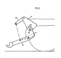
- three recesses or bores 64 and a bore designed as a bearing 66 are made in the lower corner region 56, the three bores 64 being arranged on a quarter circle around this bearing 66 and each having the same diameter, but which is smaller than the diameter of the Bearing 66.
- a total of four identical plates 24 are provided, of which an outer one is attached to the outside of the left and right web 46 and an inner one is attached to the front section of the frame 22.
- the inner plates 24 welded to the front section of the frame 22 have a recess which corresponds to the area of the frame 22 covered by the outer plate 24, so that they can be pushed onto the legs 42, 44 of the frame 22 and welded thereon.
- a fork-shaped bracket is formed on the frame 22 on each side of the tractor 12 with a space between the two inner and outer plates 24 belonging together.
- the respectively corresponding bores 60, 64, 66 in the plates 24 lie on axes running at right angles to the longitudinal center axis of the agricultural tractor 12.
- the front linkage 20 As a stiffening and bracing of the front linkage 20 against laterally, i.e. transversely to the longitudinal center axis of the agricultural tractor 12, there is a tube between the inner plates 24 concentric to the central axis of the bores 60 of the upper corner areas 54 and concentric to the central axis of the bearings 66 of the lower corner areas 56 68 and 70 is provided, which is screwed or welded to the sides of the inner plates 24 facing the longitudinal center axis of the agricultural tractor 12.
- the cross member 38 of the frame 22 also extends between the inner plates 24 and is either welded to them or screwed on via angle pieces 72. This ensures that the inner spaces 48 of the frame 22 are open towards the front in the area between the inner and outer plates 24.
- the space 48 formed between the plates 24 serves on the one hand to accommodate the lifting arm 26 and on the other hand to accommodate the Outrigger 34.
- Each lifting arm 26 consists of two angle levers 74 with two legs 76 which run at an angle of approximately 105 ° to one another and which are connected to one another in a form-fixed manner via a bushing 78 arranged in the meeting point of the two legs 76, as can be seen in FIG .
- a bore (not shown in the drawing) for receiving the shaft 62 and bearing bolts 80 and 82 is provided.
- the longitudinal center axis of the bore located at the point of intersection of the legs 76 is at the same time the longitudinal center axis of the sleeve 78, that is to say they are arranged concentrically with one another.
- the sleeves 78 receive the shaft 62 in a rotationally fixed manner, so that the lifting arms 26 can be pivoted vertically together with the shaft 62 between the plates 24 which belong together. If necessary, a plurality of bores can also be arranged for receiving the shaft 62, so as to additionally enable an adjustment of the lifting arm 26, as a result of which the lifting height and / or the lifting range of the lower link 32 can optionally also be displaced with the arms 34. Of course, the tube 68 would then have to be shifted accordingly.
- the end of the lifting arms 26 facing the agricultural tractor 12 becomes the rear fork end 84 and the end remote from the agricultural tractor 12 End designated as the front fork end 86.
- the rear fork end 84 of the lifting arm 26 receives, via the bearing pin 82, one end of a piston rod 92 protruding from a cylinder housing 88 of a hydraulic cylinder 90 used as a lifting device, the cylinder housing 88 pivotably engaging a holder 94 welded into the interior 48 of the frame 22.
- the piston rod 92 can extend up to the lifting arm 26, since the frame 22 between the plates 24 is open towards the front.
- the hydraulic cylinder 90 is connected via lines, not shown, to a control valve, likewise not shown, via which, after appropriate operation by an operator, hydraulic fluid can be supplied to the hydraulic cylinder 90, whereupon the piston rod 92 moves out of the cylinder housing 88 or slides back into the latter.
- Pressurization of the piston-side end of the hydraulic cylinder 90 causes the piston rod 92 to move out of the cylinder housing 88 and to give the lifting arm 26 a pivotal movement in the clockwise direction with respect to FIG. 1.
- the opening of the frame 22 between the plates 24 is selected to be large enough that the piston arm 92 of the lifting arm 26 is completely retracted still partially protrudes into the interior 48 of the frame 22.
- the front fork end 86 accommodates the lifting strut 30 in a vertically pivotable manner via the bearing pin 80, which, in a conventional manner, consists of an upper and a lower threaded part 96 and 98 and a form-fitting threaded sleeve 100, the threads of the upper and the lower lower threaded part 96 and 98 are in opposite directions, so that when the threaded sleeve 100 is rotated, the total length of the lifting strut 30 either lengthens or shortens. While the upper threaded end 96 has a concealed recess in the drawing and pivots about the bearing pin 80 on the front fork end 86, the lower threaded part 98 pivots on the lower link 32.
- the lower threaded part 98 in its lower, fork-shaped end region, two mutually aligned bores that cannot be seen in the drawing, and the lower link has a number of articulation points in the form of bores 102, which can optionally be connected to the bores of the lower threaded part 98 via a bolt 104 are.
- the lower link 32 is designed as a flat steel link with a rectangular cross section, the longer leg length of which lies vertically, and has in its front region a connecting member 106, for example a catch hook or a ball coupling.
- the lower link 32 is more or less cranked outwards at 108 at the front, so based on the small width of the front linkage 20 or the distance between the spaces between the left and right plates 24 the distance of the articulation points on the device.
- bores or recesses 102 near its upper edge and arranged to the rear from the bent portions 108, three of which are provided in this exemplary embodiment immediately one behind the other and at the same distance from one another, followed closely by a fourth 110 and a fifth 112 is provided at the rear end of the lower link 32.
- one of the three front bores 102 can receive the bolt 104 for connection to the lower threaded part 98 of the lifting strut 30.
- the provision of a large number of bores 102 makes it possible to optimally connect the lifting strut 30 to the lower link 32 and to use the force that can be exerted by the hydraulic cylinder 90 in the best possible way.
- the boom 34 is in turn formed by two spaced-apart cantilever plates 114 which, in this exemplary embodiment, are each provided with seven congruent bores which are individually named below.
- the These holes are divided into two groups according to their importance, namely a first group, which is for the lifting height, and a second group, which is decisive for the lifting range of the front linkage 20.
- the first group includes five holes, four of which are 116 on an arc around the fifth 118. The radius of this circular arc corresponds to the distance between the fifth, ie rearmost bore 112 of the lower link 32 to the fourth bore 110 adjacent to it in the lower link 32.
- the fifth bore 118 of the boom plates 114 and the fourth bore 110 of the lower link 32 are constant penetrated by a bolt 120 as a pivot axis, which enables the pivoting of the lower link 32 between the boom plates 114.
- a holding element or bolt 122 can additionally be inserted through the fifth hole 112 of the lower link 32 and through one of the holes 116 located on the circular arc around the fifth hole 118 of the extension plates 114.
- the second group of bores therefore consists of only two bores or recesses, namely a larger one and one. smaller 124 and 126.
- a bushing 128 rigidly interconnecting the two boom plates 114 is welded in, which is used for the continuous reception of a between the outer boom plates 114 of the left and the right side of the front linkage 20 extending shaft 130 serves as a pivot axis.
- This shaft 130 and the shaft 62 extending through the bores 60 in the upper corner region 54 of the plates 24 each run in the tubes 68, 70 connecting the inner plates 24.
- the two cantilever plates 114 on each side are thus common between the plates 24 and around the shaft 130 is pivoted vertically.
- the smaller bore 126 of the second group is located from the larger bore 124 by the radius of the holes 64 in the plates 24 on the quarter circle to the bearing 66, so that the smaller bore 126 of the second group with one of the three holes 64 in the brought lower cover area of the plates 24 in register and through which the bolt 122 can be inserted. Therefore, the bolt 122 can be inserted either only through the smaller hole 126 of the second group and through one of the holes 64 in the plate 24 or through one of the holes 116 in the first group and through the fifth hole 112 in the lower link 32, otherwise the lower link 32 can no longer be pivoted vertically, but instead acts rigidly on the plates 24.
- the holder 36 for the upper link is welded or screwed onto the tube 68 connecting the upper corner regions 54 of the inner plates 24 and the cross member 38, as can be seen in particular from FIG. 2.
- the meaning of the individual parts of the front linkage and its function can be explained as follows using the above.
- the height of the lower link 32 of the front linkage 20 is adjusted by pressurizing the hydraulic cylinders 90 on the piston side and thereby pivoting the lifting arms 26 in a clockwise direction of rotation, as previously described. These in turn take the lower links 32 with them via the lifting struts 30, so that they also perform a pivoting movement clockwise either around the shaft 130 in the larger bore 124 of the second group or about the bolt 120 in the fifth bore 112 of the first group.
- the lower link 32 is lowered analogously to the lifting, either by reducing the pressure at the piston-side end or by building up pressure at the piston rod-side end of the hydraulic cylinder 90.
- Whether the pivoting movement takes place around the shaft 130 or about the bolt 120 depends on the lifting range or the lifting height in which the lower links 32 are to move, with the area covered by the lower links 32 possibly covered by the arms 34 under the lifting range before the tractor 12 is to be understood.
- the lifting height can be moved four times and the lifting range three times.
- the lifting height is changed by aligning the fifth bore 112 of the lower link 32 with one of the four bores 116, which lie on the circular arc around the fifth bore 118 of the first group, and the bolt 122 through the aligned bores 112, 116 is inserted and secured.
- the stroke range depends on the combination of the smaller bore 126 of the second group and one of the three bores 64 in the lower corner region 56 of the plates 24 (see FIG. 3).
- the provision of the three bores 102 in the lower link 32 enables the lifting strut 30 to be repositioned in such a way that the distance between the front fork end 86 of the lifting arm 26 and the relevant bore 102 of the lower link 32 remains at least largely the same.
- the lifting strut 30 is separated from the lifting arm 26 in a simple manner, the lower link 32 is pivoted upward and with the lifting strut 30 on the frame 22 on the main frame 18 of the tractor 12 holding bolts 50, in particular its shaft part 52, secured.
- the lower links 32 are then no longer hazardous to the front of the tractor 12, but run close and at least substantially parallel to the front part 10 of the tractor 12, so that the relevant safety regulations are observed.
- Other applications could be a loading platform on a loading ramp, a connecting rod of a clearing vehicle, a connecting rod of a loader with the loading equipment or a three-point device coupling at the rear end of an agricultural vehicle.
Claims (14)
Priority Applications (1)
| Application Number | Priority Date | Filing Date | Title |
|---|---|---|---|
| AT85113050T ATE29474T1 (de) | 1984-10-25 | 1985-10-15 | Kraftheber fuer ein hubgeraet. |
Applications Claiming Priority (2)
| Application Number | Priority Date | Filing Date | Title |
|---|---|---|---|
| DE3439048A DE3439048C2 (de) | 1984-10-25 | 1984-10-25 | Kraftheber für ein Hubgerät |
| DE3439048 | 1984-10-25 |
Publications (2)
| Publication Number | Publication Date |
|---|---|
| EP0182091A1 EP0182091A1 (fr) | 1986-05-28 |
| EP0182091B1 true EP0182091B1 (fr) | 1987-09-09 |
Family
ID=6248718
Family Applications (1)
| Application Number | Title | Priority Date | Filing Date |
|---|---|---|---|
| EP85113050A Expired EP0182091B1 (fr) | 1984-10-25 | 1985-10-15 | Elévateur de puissance pour un dispositif de levage |
Country Status (9)
| Country | Link |
|---|---|
| US (1) | US4715770A (fr) |
| EP (1) | EP0182091B1 (fr) |
| JP (1) | JPH0624444B2 (fr) |
| AT (1) | ATE29474T1 (fr) |
| AU (1) | AU573041B2 (fr) |
| CA (1) | CA1248057A (fr) |
| DE (2) | DE3439048C2 (fr) |
| ES (1) | ES8701680A1 (fr) |
| ZA (1) | ZA858178B (fr) |
Families Citing this family (23)
| Publication number | Priority date | Publication date | Assignee | Title |
|---|---|---|---|---|
| AT388362B (de) * | 1986-06-24 | 1989-06-12 | Steyr Daimler Puch Ag | An einem landwirtschaftlichen nutzfahrzeug angeordnetes hubwerk fuer den wahlweisen anbau von mit anschlusszapfen oder -bolzen versehenen geraeten |
| JPS6328305U (fr) * | 1986-08-11 | 1988-02-24 | ||
| US4899831A (en) * | 1986-12-22 | 1990-02-13 | J. I. Case Company | Frontal connection apparatus for tractors |
| DE3938418C1 (fr) * | 1989-11-18 | 1991-03-21 | Jean Walterscheid Gmbh, 5204 Lohmar, De | |
| FR2688378B1 (fr) * | 1992-03-12 | 1996-09-06 | Hubert Defrancq | Dispositif de relevage avant, pour tracteur agricole ou analogue, et porte-masse pour un tel dispositif |
| GB2289834A (en) * | 1994-05-14 | 1995-12-06 | Cannington College | Tractor hitch |
| DE19501143B4 (de) * | 1995-01-17 | 2015-04-23 | Josef Nusser | Frontkraftheber für Traktoren |
| DE19606061B4 (de) * | 1996-01-18 | 2015-10-01 | Josef Nusser | Frontkraftheber für Traktoren |
| AT407383B (de) * | 1996-01-29 | 2001-02-26 | Nussmueller Landtechnik Gmbh | Hebevorrichtung für lasten |
| FR2769789B1 (fr) | 1997-10-22 | 1999-12-31 | Hubert Defrancq | Dispositif de relevage, en particulier de relevage avant, pour tracteur agricole ou analogue |
| US20050167533A1 (en) * | 2004-01-05 | 2005-08-04 | Christy Jody M. | Apparatus for spreading particulate material from a work vehicle |
| GB0606849D0 (en) * | 2006-04-04 | 2006-05-17 | Agco Sa | Tractor front hitches |
| GB2443600A (en) * | 2006-06-17 | 2008-05-14 | Agco Gmbh | Mounting device having variably spaced arms |
| US8602153B2 (en) * | 2007-08-06 | 2013-12-10 | Extendquip Llc | Extendable frame work vehicle |
| FR2937827B1 (fr) * | 2008-10-30 | 2013-02-15 | Hubert Defrancq | Dispositif de relevage avant pour tracteur. |
| GB201000537D0 (en) * | 2010-01-14 | 2010-03-03 | Agco Sa | Tractor implement support linkage |
| US8496070B2 (en) * | 2010-09-20 | 2013-07-30 | Deere & Company | Folding hitch lift arm |
| US9788471B2 (en) | 2014-12-23 | 2017-10-17 | Deere & Company | Link assembly |
| FR3037769B1 (fr) | 2015-06-23 | 2017-07-21 | Hubert Defrancq | Dispositif de relevage avant pour engin agricole et procede de commande associe. |
| US10398083B2 (en) * | 2015-09-09 | 2019-09-03 | Deere & Company | Multi head windrower |
| EP3571908B1 (fr) | 2018-05-23 | 2022-08-10 | AGCO International GmbH | Attelage pliant |
| JP7114498B2 (ja) * | 2019-01-30 | 2022-08-08 | ヤンマーパワーテクノロジー株式会社 | 作業車両 |
| US20210332543A1 (en) * | 2020-04-28 | 2021-10-28 | Johnston Landscape Maintenance Inc. | Adapter assemblies and methods for mounting implements and accessories to passenger vehicles therewith |
Family Cites Families (14)
| Publication number | Priority date | Publication date | Assignee | Title |
|---|---|---|---|---|
| GB565837A (en) * | 1943-02-25 | 1944-11-30 | Percy Burnell Bettinson | Improvements in multi-purpose agricultural machines |
| US2609741A (en) * | 1948-08-30 | 1952-09-09 | Evenson Ernest | Cultivator attachment for tractors |
| GB863270A (en) * | 1957-05-27 | 1961-03-22 | Timothy Fogden | Load handling attachment for use with tractors |
| US3031208A (en) * | 1960-10-25 | 1962-04-24 | Paul D Abbott | Universal tractor hitch |
| US3214138A (en) * | 1963-12-23 | 1965-10-26 | Int Harvester Co | Hydraulic lift for dozer blade |
| US3285625A (en) * | 1964-12-29 | 1966-11-15 | Wausau Iron Works | Quick coupler |
| US3441091A (en) * | 1967-04-10 | 1969-04-29 | Glenn Helling | Tool mounting assembly |
| GB1513139A (en) * | 1974-09-19 | 1978-06-07 | Massey Ferguson Perkins Ltd | Material handling apparatus |
| DE2506745C3 (de) * | 1975-02-18 | 1978-06-22 | Xaver Fendt & Co, 8952 Marktoberdorf | Geräteanbauvorrichtung für eine landwirtschaftlich nutzbare Zugmaschine |
| FR2302012A1 (fr) * | 1975-02-25 | 1976-09-24 | Agram | Berceau porte-outil susceptible d'etre accouple sur l'avant d'un vehicule automoteur |
| JPS54135308U (fr) * | 1978-03-13 | 1979-09-19 | ||
| ATE21000T1 (de) * | 1981-04-22 | 1986-08-15 | Deere & Co | Land- und/oder bauwirtschaftlich nutzbares kraftfahrzeug mit frontseitiger geraeteanbauvorrichtung. |
| US4519623A (en) * | 1983-05-09 | 1985-05-28 | Orthman Manufacturing, Inc. | Tractor front end hitch |
| US4558881A (en) * | 1983-10-11 | 1985-12-17 | Ingersoll Equipment Co., Inc. | Tractor-mounted implement hitch arrangement |
-
1984
- 1984-10-25 DE DE3439048A patent/DE3439048C2/de not_active Expired
-
1985
- 1985-10-15 AT AT85113050T patent/ATE29474T1/de active
- 1985-10-15 EP EP85113050A patent/EP0182091B1/fr not_active Expired
- 1985-10-15 DE DE8585113050T patent/DE3560571D1/de not_active Expired
- 1985-10-18 CA CA000493324A patent/CA1248057A/fr not_active Expired
- 1985-10-23 AU AU48992/85A patent/AU573041B2/en not_active Ceased
- 1985-10-24 ES ES85548165A patent/ES8701680A1/es not_active Expired
- 1985-10-24 ZA ZA858178A patent/ZA858178B/xx unknown
- 1985-10-25 JP JP60239267A patent/JPH0624444B2/ja not_active Expired - Lifetime
-
1987
- 1987-02-05 US US07/013,214 patent/US4715770A/en not_active Expired - Fee Related
Also Published As
| Publication number | Publication date |
|---|---|
| CA1248057A (fr) | 1989-01-03 |
| JPS61104707A (ja) | 1986-05-23 |
| ZA858178B (en) | 1987-06-24 |
| US4715770A (en) | 1987-12-29 |
| DE3560571D1 (en) | 1987-10-15 |
| ATE29474T1 (de) | 1987-09-15 |
| JPH0624444B2 (ja) | 1994-04-06 |
| AU573041B2 (en) | 1988-05-26 |
| DE3439048A1 (de) | 1986-05-07 |
| AU4899285A (en) | 1986-05-01 |
| EP0182091A1 (fr) | 1986-05-28 |
| ES548165A0 (es) | 1986-12-01 |
| ES8701680A1 (es) | 1986-12-01 |
| DE3439048C2 (de) | 1986-09-11 |
Similar Documents
| Publication | Publication Date | Title |
|---|---|---|
| EP0182091B1 (fr) | Elévateur de puissance pour un dispositif de levage | |
| DE3517853A1 (de) | Ausfahrbare vorrichtung | |
| EP2186713A2 (fr) | Dispositif de ballastage et véhicule agricole équipé avec ce dernier | |
| DE202004011990U1 (de) | Umschlaggerät | |
| EP1800529B2 (fr) | Faucheuse | |
| DE19939967C2 (de) | Hubwerk für Unterlenker einer Anbaueinrichtung eines Traktors | |
| EP1131499A1 (fr) | Chargeuse pelleteuse mobile | |
| DE10126029B4 (de) | Hydraulisches Hubwerk für eine Anbaueinrichtung | |
| DE2411051A1 (de) | Arbeitsmaschine fuer tiefbauarbeiten, insbesondere schaufellader | |
| EP2042410B1 (fr) | Véhicule agricole | |
| DE2743087C3 (de) | Lenkeinrichtung für mindestens ein rückwärtiges Laufrad eines Pfluges | |
| EP0426005A1 (fr) | Structure d'accouplement | |
| DE2648611C2 (fr) | ||
| DE1932040A1 (de) | Gewichtsuebertragungskupplung | |
| WO2002095142A1 (fr) | Excavatrice sur roues | |
| DE2936688A1 (de) | Zur handhabung schwerer lasten dienende drehbare vorrichtung | |
| EP0955230B1 (fr) | Véhicule utilitaire avec plate-forme de conduite basculante et mécanisme de basculement | |
| EP0439068A1 (fr) | Machine agricole | |
| DE3319157A1 (de) | Schleppvorrichtung fuer ein abschleppfahrzeug | |
| DE2027259B2 (de) | Be- und Entladeeinrichtung für Behälter od.dgl. an Fahrzeugen | |
| EP3636520A1 (fr) | Dispositif de ballastage et véhicule agricole | |
| DE3448426C2 (de) | Landwirtschaftliche Maschine | |
| DE19620944C1 (de) | Abstützeinrichtung mit Querbewegungsantrieb für mobile Arbeitsgeräte | |
| DE19708316A1 (de) | Fahrbares Arbeitsgerät | |
| DE1557820C (de) | Anbauvorrichtung für landwirtschaftliche Geräte |
Legal Events
| Date | Code | Title | Description |
|---|---|---|---|
| PUAI | Public reference made under article 153(3) epc to a published international application that has entered the european phase |
Free format text: ORIGINAL CODE: 0009012 |
|
| AK | Designated contracting states |
Kind code of ref document: A1 Designated state(s): AT BE CH DE FR GB IT LI SE |
|
| 17P | Request for examination filed |
Effective date: 19860612 |
|
| 17Q | First examination report despatched |
Effective date: 19870128 |
|
| ITF | It: translation for a ep patent filed |
Owner name: LENZI & C. |
|
| GRAA | (expected) grant |
Free format text: ORIGINAL CODE: 0009210 |
|
| AK | Designated contracting states |
Kind code of ref document: B1 Designated state(s): AT BE CH DE FR GB IT LI SE |
|
| REF | Corresponds to: |
Ref document number: 29474 Country of ref document: AT Date of ref document: 19870915 Kind code of ref document: T |
|
| REF | Corresponds to: |
Ref document number: 3560571 Country of ref document: DE Date of ref document: 19871015 |
|
| ET | Fr: translation filed | ||
| GBT | Gb: translation of ep patent filed (gb section 77(6)(a)/1977) | ||
| PG25 | Lapsed in a contracting state [announced via postgrant information from national office to epo] |
Ref country code: LI Effective date: 19871031 Ref country code: CH Effective date: 19871031 |
|
| REG | Reference to a national code |
Ref country code: CH Ref legal event code: PL |
|
| PLBE | No opposition filed within time limit |
Free format text: ORIGINAL CODE: 0009261 |
|
| STAA | Information on the status of an ep patent application or granted ep patent |
Free format text: STATUS: NO OPPOSITION FILED WITHIN TIME LIMIT |
|
| 26N | No opposition filed | ||
| PGFP | Annual fee paid to national office [announced via postgrant information from national office to epo] |
Ref country code: BE Payment date: 19911023 Year of fee payment: 7 |
|
| PG25 | Lapsed in a contracting state [announced via postgrant information from national office to epo] |
Ref country code: BE Effective date: 19921031 |
|
| BERE | Be: lapsed |
Owner name: DEERE & CY Effective date: 19921031 |
|
| PGFP | Annual fee paid to national office [announced via postgrant information from national office to epo] |
Ref country code: AT Payment date: 19931020 Year of fee payment: 9 |
|
| PGFP | Annual fee paid to national office [announced via postgrant information from national office to epo] |
Ref country code: SE Payment date: 19931025 Year of fee payment: 9 |
|
| ITTA | It: last paid annual fee | ||
| PG25 | Lapsed in a contracting state [announced via postgrant information from national office to epo] |
Ref country code: AT Effective date: 19941015 |
|
| PG25 | Lapsed in a contracting state [announced via postgrant information from national office to epo] |
Ref country code: SE Effective date: 19941016 |
|
| EAL | Se: european patent in force in sweden |
Ref document number: 85113050.0 |
|
| EUG | Se: european patent has lapsed |
Ref document number: 85113050.0 |
|
| PGFP | Annual fee paid to national office [announced via postgrant information from national office to epo] |
Ref country code: GB Payment date: 19970916 Year of fee payment: 13 |
|
| PGFP | Annual fee paid to national office [announced via postgrant information from national office to epo] |
Ref country code: FR Payment date: 19971016 Year of fee payment: 13 |
|
| PGFP | Annual fee paid to national office [announced via postgrant information from national office to epo] |
Ref country code: DE Payment date: 19971128 Year of fee payment: 13 |
|
| PG25 | Lapsed in a contracting state [announced via postgrant information from national office to epo] |
Ref country code: GB Free format text: LAPSE BECAUSE OF NON-PAYMENT OF DUE FEES Effective date: 19981015 |
|
| GBPC | Gb: european patent ceased through non-payment of renewal fee |
Effective date: 19981015 |
|
| PG25 | Lapsed in a contracting state [announced via postgrant information from national office to epo] |
Ref country code: FR Free format text: LAPSE BECAUSE OF NON-PAYMENT OF DUE FEES Effective date: 19990630 |
|
| REG | Reference to a national code |
Ref country code: FR Ref legal event code: ST |
|
| PG25 | Lapsed in a contracting state [announced via postgrant information from national office to epo] |
Ref country code: DE Free format text: LAPSE BECAUSE OF NON-PAYMENT OF DUE FEES Effective date: 19990803 |