EP0176606B1 - Einrichtung zum Aufbringen und Weitertransportieren eines Schutzüberzuges für eine Klosettbrille - Google Patents
Einrichtung zum Aufbringen und Weitertransportieren eines Schutzüberzuges für eine Klosettbrille Download PDFInfo
- Publication number
- EP0176606B1 EP0176606B1 EP84111514A EP84111514A EP0176606B1 EP 0176606 B1 EP0176606 B1 EP 0176606B1 EP 84111514 A EP84111514 A EP 84111514A EP 84111514 A EP84111514 A EP 84111514A EP 0176606 B1 EP0176606 B1 EP 0176606B1
- Authority
- EP
- European Patent Office
- Prior art keywords
- switching tube
- collecting reel
- housing
- reel
- switch
- Prior art date
- Legal status (The legal status is an assumption and is not a legal conclusion. Google has not performed a legal analysis and makes no representation as to the accuracy of the status listed.)
- Expired
Links
- 230000001681 protective effect Effects 0.000 title claims abstract description 24
- 230000003213 activating effect Effects 0.000 claims abstract 2
- 230000000994 depressogenic effect Effects 0.000 claims abstract 2
- 230000004323 axial length Effects 0.000 claims description 2
- 230000003100 immobilizing effect Effects 0.000 claims 3
- 238000005192 partition Methods 0.000 description 9
- 238000006073 displacement reaction Methods 0.000 description 3
- 230000005540 biological transmission Effects 0.000 description 2
- 230000033001 locomotion Effects 0.000 description 2
- 230000002093 peripheral effect Effects 0.000 description 2
- 238000011109 contamination Methods 0.000 description 1
- 230000018109 developmental process Effects 0.000 description 1
- 239000011521 glass Substances 0.000 description 1
- 239000011253 protective coating Substances 0.000 description 1
- XLYOFNOQVPJJNP-UHFFFAOYSA-N water Substances O XLYOFNOQVPJJNP-UHFFFAOYSA-N 0.000 description 1
- 238000004804 winding Methods 0.000 description 1
Images
Classifications
-
- A—HUMAN NECESSITIES
- A47—FURNITURE; DOMESTIC ARTICLES OR APPLIANCES; COFFEE MILLS; SPICE MILLS; SUCTION CLEANERS IN GENERAL
- A47K—SANITARY EQUIPMENT NOT OTHERWISE PROVIDED FOR; TOILET ACCESSORIES
- A47K13/00—Seats or covers for all kinds of closets
- A47K13/14—Protecting covers for closet seats
- A47K13/145—Protecting covers for closet seats of rolled-up paper tubes or rolled-up plastic tubes
Definitions
- the invention relates to a device for applying and transporting a tubular protective cover for a toilet seat, with a housing to be fastened to the toilet seat, which contains a reel from which the protective cover is removed, and a reel which can be driven by a battery-operated electric motor and onto which the protective cover is rolled up again after use, a push button on the side of the unwinding spool from the housing standing in front for actuating a switch arranged on the opposite side of the unwinding spool for the electric motor can be pressed in the axial direction of the unwinding spool.
- a device of this type which provides for direct storage of the unwinding spool in the walls of the housing, the entire unwinding spool being axially displaced when the push button is pressed and pressing the opposite end of the switch, so that the electric motor is started.
- An arrangement of all electrical parts, namely the electric motor, the battery, and the switch, in a central compartment of the housing, which is closed off by dividing walls, is separate from the compartments provided for the reel spool and take-up spool, with a view to protecting the electrical parts from water, contamination and the like desirable.
- actuation of the electric motor from the side of the unwinding spool is expedient, since only at this point, on the one hand, a collision with the transmission for driving the reel spool and, on the other hand, inaccessibility in the opened or unfolded state of the housing with regard to the fact that the toilet seat can be opened Toilet glasses are avoided.
- the thrust transmission of the push button over the unwinding spool leads to a slight hindrance to the unrolling of the protective cover during pressing, so that the latter can only freely follow the pull exerted by the electric motor after releasing the push button. This will delay the application of an unused piece of the protective cover and may cause distortion.
- the invention is intended to improve the known device in such a way that a free and unimpeded starting of the unwinding spool can take place immediately when the push button is actuated.
- a switching tube which is in axial thrust connection with the push button for the actuation of the switch is axially displaceably mounted in the housing and that the unwinding spool is rotatably and axially displaceably mounted on the switching tube.
- the switch is preferably designed as a pressure switch, so that when the push button is pressed axially in via the switching tube, the pressure switch is actuated and the motor is switched on. When the push button is released, the spring-loaded action resets the push switch and pushes the switching tube into the starting position.
- the switching tube can rotate when the unwinding spool is turned.
- the pushbutton which is visible from the outside, from rotating, it can itself be mounted on the housing so as to be axially displaceable separately from the switching tube.
- the switching tube has retaining members which engage in an axially displaceable manner in its direction of rotation in sections of a housing wall.
- the push button can also be firmly connected to the switching tube or even be made in one piece with it.
- limiting members for limiting the axial play of the unwinding reel protrude from housing walls arranged on both sides of the axial ends of the unwinding reel.
- the push button can be firmly connected to the switching tube. But it can also sit firmly, but releasably on the switching tube, so that it can be pulled off to attach a new unwinding spool.
- the holding members which are preferably seated at the opposite end, to form a holding part which can be frictionally inserted into the open end of the switching tube and which can be removed from the inside for plugging in the new roll-off spool.
- the switch for the motor consists of two spring contacts arranged next to one another in a plane perpendicular to the axial direction of the roll-off spool, and the front end of the switching tube opposite the spring contacts is electrically conductive for establishing a connection between the spring contacts.
- the switching tube near each of its two ends has an all-round projecting flange, which is arranged inside the bearing walls for the switching tube and outside the ends of the unwinding spool is. This allows the unwinding spool to move freely on the switching tube, but is held in the axial direction by the flanges.
- the switching tube with the flanges is also replaced as a disposable unit when the reel spool is replaced.
- the switching tube is made of plastic, this is not associated with high costs.
- the flanges are designed to be elastic, they can moreover be used so that at least one of them, preferably the flange close to the switch, bears against an inner housing stop near its circumferential edge.
- the flange is slightly bent and, after releasing the push button, ensures that the switching tube is returned to the starting position due to its elastic force.
- Such a stop can also be provided on the opposite flange in order to precisely set the middle position of the switching tube.
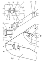
- the housing has a lower part, generally designated 10, and an upper part 12, not shown in FIG. 1.
- the lower part 10 and upper part 12 together form a closed housing, with their edges lying close together.
- a partition wall 14 and 16 of the housing 10, 12 forms a bearing seat 18 for a switching tube 20, which at one end carries an adapter 22 arranged outside the partition wall 14, 16 for receiving a push button 23 shown only in FIG. 1 a.
- the push button 23 is in turn mounted axially displaceably in an outer wall of the housing 10, 12, not shown.
- a holding part, generally designated 24, sits in one piece.
- the holding part 24 has two annular sector-shaped holding members 26, which are arranged non-rotatably, but axially displaceably, in cutouts 28 of an inner partition 30, 31 of the housing 10, 12.
- the free end 32 of at least one of the holding members 26 presses against the free end of a leaf spring 34, the other end of which is attached to a pressure switch 36.
- the leaf spring 34 normally pushes the switching tube 20 into the non-actuated outer position, which is shown in FIGS. 3 and 4. It is held in this position by a stop 35 seated on the partition 30, which abuts the holding part 24.
- the adapter 22 is at a small distance from the partition 14, 16 of the housing to the outside and can be pressed in by pressing the push button 23 until it stops on the webs 48 on the housing.
- the pushbutton 23 is pressed in, the free end 32 of the holding members 26 presses against the leaf spring 34.
- the displacement of this pushbutton actuates the actuating button 38 of the pushbutton 36 and sets the electric motor (not shown) in motion.
- the electric motor is located in the same central compartment of the housing 10, 12 formed by the partition wall 30, 31 and a further partition wall, not shown, as the pressure switch 36 and the battery, not shown.
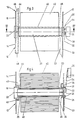
- the unwinding spool 40 which is shown empty in FIG. 1, is seated on the switching tube 20 in a freely rotatable and axially displaceable manner, while according to FIGS. 3 and 4 a supply of tubular protective cover 42, for example made of plastic, is wound up.
- the end of the protective cover 42 is put on the open end of the toilet seat and led to the reel spool located at the opposite end, whereby it is automatically cut open laterally before winding.
- push button 23 is pressed via the pressure switch 36 the electric motor, not shown, is started and thus the reel is rotated so that the used piece of protective cover is pulled off the toilet seat and rolled up. At the same time, a new piece is pulled off the reel spool 40 and then covers the toilet seat.
- the webs 48 and 50 projecting from the side wall 14 and the partition 30 are at their axial ends 44 and 46 with large axial play.
- these webs 48 and 50 exert extremely little friction when the unwinding spool 40 rotates, but on the other hand fix the axial position of the unwinding spool 40 to a certain extent, so that the protective covering 42 pulled off the unwinding spool 40 is undistorted and in an approximately straight direction to the subsequent End of the toilet seat not shown can be put on.
- this axial position of the unwinding spool is only marginally influenced by the actuation of the pushbutton 23, and the running off of the protective cover 42 from the unwinding spool is thus largely independent of the actuation of the pushbutton 23.
- the two axial ends 44 and 46 of the unwind spool 40 protrude slightly beyond the width of the protective cover 42.
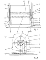
- the upper housing part 12 is removed from the lower part 10 and the switching tube 20 with the unwind spool 40 is removed from its bearings 18, 28. Then a new switching tube 20 is inserted with a full unwind spool 40, the beginning of the protective cover 42 is pulled over the toilet seat and fastened to the reel spool, not shown, and then the housing is closed again.
- a radially projecting flange 52 or 54 is provided on each side, within which the unwinding spool 40 is rotatably mounted with play to the switching tube 20.
- the holding members 26 are attached in one piece, the end 58 of at least one holding member 26 being electrically conductive.
- two spring contacts 62, 64 are arranged in a plane perpendicular to the longitudinal axis 60 of the switching tube 20, which are connected to the motor in a manner not shown.
- the conductive end 58 When the push button 23 is pressed in, the conductive end 58 is connected to the two spring contacts 62, 64 and the motor is thereby switched on. During this axial displacement of the switching tube 20, the peripheral edge 65 of the elastic flange 54, which in the rest position shown rests against an inner stop 66 of the lower part 10, is elastically bent. After releasing the push button 23, the switching tube 20 is returned to its starting position by the elastic force of the bent peripheral edge 65.
- the tube extension 56 is axially freely displaceable in a circular recess 68 of the partition 30, 31.
Landscapes
- Health & Medical Sciences (AREA)
- Public Health (AREA)
- Toilet Supplies (AREA)
- Storing, Repeated Paying-Out, And Re-Storing Of Elongated Articles (AREA)
Priority Applications (4)
| Application Number | Priority Date | Filing Date | Title |
|---|---|---|---|
| DE3329157A DE3329157A1 (de) | 1983-08-12 | 1983-08-12 | Einrichtung zum aufbringen und weitertransportieren eines schutzueberzuges fuer eine klosettbrille |
| DE8484111514T DE3471245D1 (en) | 1983-08-12 | 1984-09-27 | Device for fitting and replacing a protective toilet seat cover |
| EP84111514A EP0176606B1 (de) | 1983-08-12 | 1984-09-27 | Einrichtung zum Aufbringen und Weitertransportieren eines Schutzüberzuges für eine Klosettbrille |
| AT84111514T ATE34292T1 (de) | 1983-08-12 | 1984-09-27 | Einrichtung zum aufbringen und weitertransportieren eines schutzueberzuges fuer eine klosettbrille. |
Applications Claiming Priority (2)
| Application Number | Priority Date | Filing Date | Title |
|---|---|---|---|
| DE3329157A DE3329157A1 (de) | 1983-08-12 | 1983-08-12 | Einrichtung zum aufbringen und weitertransportieren eines schutzueberzuges fuer eine klosettbrille |
| EP84111514A EP0176606B1 (de) | 1983-08-12 | 1984-09-27 | Einrichtung zum Aufbringen und Weitertransportieren eines Schutzüberzuges für eine Klosettbrille |
Publications (2)
| Publication Number | Publication Date |
|---|---|
| EP0176606A1 EP0176606A1 (de) | 1986-04-09 |
| EP0176606B1 true EP0176606B1 (de) | 1988-05-18 |
Family
ID=25813142
Family Applications (1)
| Application Number | Title | Priority Date | Filing Date |
|---|---|---|---|
| EP84111514A Expired EP0176606B1 (de) | 1983-08-12 | 1984-09-27 | Einrichtung zum Aufbringen und Weitertransportieren eines Schutzüberzuges für eine Klosettbrille |
Country Status (3)
| Country | Link |
|---|---|
| EP (1) | EP0176606B1 (cg-RX-API-DMAC7.html) |
| AT (1) | ATE34292T1 (cg-RX-API-DMAC7.html) |
| DE (2) | DE3329157A1 (cg-RX-API-DMAC7.html) |
Families Citing this family (2)
| Publication number | Priority date | Publication date | Assignee | Title |
|---|---|---|---|---|
| JPH0249038Y2 (cg-RX-API-DMAC7.html) * | 1984-10-11 | 1990-12-21 | ||
| US12064063B2 (en) | 2019-09-23 | 2024-08-20 | Gpcp Ip Holdings Llc | Automated toilet seat cover dispenser |
Family Cites Families (4)
| Publication number | Priority date | Publication date | Assignee | Title |
|---|---|---|---|---|
| FR590926A (fr) * | 1924-12-09 | 1925-06-25 | Distributeur automatique | |
| CH116561A (de) * | 1925-12-01 | 1927-01-03 | Emil Zerkiebel | Elektrische Antriebseinrichtung bei Abortsitzen mit beweglichem Schutzpapierband. |
| DE660709C (de) * | 1936-01-05 | 1938-06-01 | Hans Von Waldthausen Dr | Vorrichtung zum UEberziehen von Klosettsitzen mit einer mit Sitzausschnitten versehenen Schutzbahn |
| DE2857561C3 (de) * | 1977-09-07 | 1981-12-10 | Hygomat AG, Zug | Klosettbrille mit einer Einrichtung zum Aufbringen und Weitertransportieren eines Schutzüberzugs für die Klosettbrille |
-
1983
- 1983-08-12 DE DE3329157A patent/DE3329157A1/de active Granted
-
1984
- 1984-09-27 EP EP84111514A patent/EP0176606B1/de not_active Expired
- 1984-09-27 DE DE8484111514T patent/DE3471245D1/de not_active Expired
- 1984-09-27 AT AT84111514T patent/ATE34292T1/de not_active IP Right Cessation
Also Published As
| Publication number | Publication date |
|---|---|
| ATE34292T1 (de) | 1988-06-15 |
| DE3471245D1 (en) | 1988-06-23 |
| DE3329157C2 (cg-RX-API-DMAC7.html) | 1989-08-10 |
| EP0176606A1 (de) | 1986-04-09 |
| DE3329157A1 (de) | 1985-02-21 |
Similar Documents
| Publication | Publication Date | Title |
|---|---|---|
| DE3610329C2 (cg-RX-API-DMAC7.html) | ||
| EP0313720B1 (de) | Handgerät zum Übertragen eines Filmes von einer Trägerfolie auf ein Substrat | |
| EP0757525B1 (de) | Nachfüllbarer behälter zur abgabe einer streichfähigen masse, insbesondere klebemasse | |
| EP0276474B1 (de) | Dosiervorrichtung | |
| DE2744953C2 (de) | Bandförder- und -abschneidevorrichtung für ein Klebeband | |
| DE2233834C3 (de) | Dosenöffner mit Motorantrieb für eine Dosendrehvorrichtung | |
| DE3109735A1 (de) | "automatischer bandspender" | |
| DE2142887B2 (de) | In einer Schalttafel montierbarer Schalter | |
| DE2649878A1 (de) | Mixer fuer den haushalt | |
| DE60109091T2 (de) | Aufladevorrichtung für Wischmaterialspender | |
| EP0176606B1 (de) | Einrichtung zum Aufbringen und Weitertransportieren eines Schutzüberzuges für eine Klosettbrille | |
| DE3729259A1 (de) | Elektrisch angetriebener dosenoeffner | |
| DE2901696C2 (de) | Handetikettiergerät zum Bedrucken, Ausgeben und Anbringen von Selbstklebeetiketten | |
| DE29709181U1 (de) | Halter für Folienrollen für Mal- und Tapezierarbeiten | |
| DE2520873A1 (de) | Rasenkantenschneider | |
| EP0469461A1 (de) | Vorrichtung zur Abgabe eines Klebebandes | |
| DE8323237U1 (de) | Einrichtung zum aufbringen und weitertransportieren eines schutzueberzugs fuer eine klosettbrille | |
| CH647578A5 (en) | Roller shutter with electric drive and automatic control | |
| DE1773679B1 (de) | Bandmass | |
| EP0046153B1 (de) | Toilettenpapierspender für die Aufnahme von mindestens zwei Papierrollen | |
| DE1652301A1 (de) | Magazin fuer die Bandrolle eines Bandpraegegeraets | |
| DE3315643C2 (de) | Automatischer Einschaltschutz | |
| DE2832557C3 (de) | Behälter für eine Magnetbandkassette | |
| EP1190973B1 (de) | Klebebandabroller | |
| DE69700601T2 (de) | Spendevorrichtung für fakultativ gefaltetes wischmaterial |
Legal Events
| Date | Code | Title | Description |
|---|---|---|---|
| PUAI | Public reference made under article 153(3) epc to a published international application that has entered the european phase |
Free format text: ORIGINAL CODE: 0009012 |
|
| 17P | Request for examination filed |
Effective date: 19860131 |
|
| AK | Designated contracting states |
Kind code of ref document: A1 Designated state(s): AT BE CH DE FR GB IT LI LU NL SE |
|
| RAP1 | Party data changed (applicant data changed or rights of an application transferred) |
Owner name: HYGOMAT PATENT AG |
|
| 17Q | First examination report despatched |
Effective date: 19870522 |
|
| ITF | It: translation for a ep patent filed | ||
| GRAA | (expected) grant |
Free format text: ORIGINAL CODE: 0009210 |
|
| AK | Designated contracting states |
Kind code of ref document: B1 Designated state(s): AT BE CH DE FR GB IT LI LU NL SE |
|
| REF | Corresponds to: |
Ref document number: 34292 Country of ref document: AT Date of ref document: 19880615 Kind code of ref document: T |
|
| GBT | Gb: translation of ep patent filed (gb section 77(6)(a)/1977) | ||
| ET | Fr: translation filed | ||
| REF | Corresponds to: |
Ref document number: 3471245 Country of ref document: DE Date of ref document: 19880623 |
|
| PLBE | No opposition filed within time limit |
Free format text: ORIGINAL CODE: 0009261 |
|
| STAA | Information on the status of an ep patent application or granted ep patent |
Free format text: STATUS: NO OPPOSITION FILED WITHIN TIME LIMIT |
|
| 26N | No opposition filed | ||
| REG | Reference to a national code |
Ref country code: CH Ref legal event code: PFA Free format text: NF PATENT AG |
|
| EPTA | Lu: last paid annual fee | ||
| ITTA | It: last paid annual fee | ||
| EAL | Se: european patent in force in sweden |
Ref document number: 84111514.0 |
|
| PGFP | Annual fee paid to national office [announced via postgrant information from national office to epo] |
Ref country code: AT Payment date: 19970825 Year of fee payment: 14 |
|
| PGFP | Annual fee paid to national office [announced via postgrant information from national office to epo] |
Ref country code: DE Payment date: 19971027 Year of fee payment: 14 |
|
| PG25 | Lapsed in a contracting state [announced via postgrant information from national office to epo] |
Ref country code: AT Free format text: LAPSE BECAUSE OF NON-PAYMENT OF DUE FEES Effective date: 19980927 |
|
| PGFP | Annual fee paid to national office [announced via postgrant information from national office to epo] |
Ref country code: SE Payment date: 19980929 Year of fee payment: 15 |
|
| PG25 | Lapsed in a contracting state [announced via postgrant information from national office to epo] |
Ref country code: DE Free format text: LAPSE BECAUSE OF NON-PAYMENT OF DUE FEES Effective date: 19990701 |
|
| PGFP | Annual fee paid to national office [announced via postgrant information from national office to epo] |
Ref country code: GB Payment date: 19990916 Year of fee payment: 16 |
|
| PG25 | Lapsed in a contracting state [announced via postgrant information from national office to epo] |
Ref country code: SE Free format text: THE PATENT HAS BEEN ANNULLED BY A DECISION OF A NATIONAL AUTHORITY Effective date: 19990929 |
|
| REG | Reference to a national code |
Ref country code: CH Ref legal event code: PUE Owner name: NF PATENT AG TRANSFER- HYGOLET (SCHWEIZ) AG |
|
| EUG | Se: european patent has lapsed |
Ref document number: 84111514.0 |
|
| NLS | Nl: assignments of ep-patents |
Owner name: HYGOLET (EUROPE) AG |
|
| PGFP | Annual fee paid to national office [announced via postgrant information from national office to epo] |
Ref country code: LU Payment date: 20000814 Year of fee payment: 17 |
|
| REG | Reference to a national code |
Ref country code: FR Ref legal event code: TP |
|
| PG25 | Lapsed in a contracting state [announced via postgrant information from national office to epo] |
Ref country code: GB Free format text: LAPSE BECAUSE OF NON-PAYMENT OF DUE FEES Effective date: 20000927 |
|
| GBPC | Gb: european patent ceased through non-payment of renewal fee |
Effective date: 20000927 |
|
| PG25 | Lapsed in a contracting state [announced via postgrant information from national office to epo] |
Ref country code: LU Free format text: LAPSE BECAUSE OF NON-PAYMENT OF DUE FEES Effective date: 20010927 |
|
| PGFP | Annual fee paid to national office [announced via postgrant information from national office to epo] |
Ref country code: BE Payment date: 20020723 Year of fee payment: 19 |
|
| PGFP | Annual fee paid to national office [announced via postgrant information from national office to epo] |
Ref country code: NL Payment date: 20020924 Year of fee payment: 19 |
|
| PGFP | Annual fee paid to national office [announced via postgrant information from national office to epo] |
Ref country code: CH Payment date: 20021203 Year of fee payment: 19 |
|
| PGFP | Annual fee paid to national office [announced via postgrant information from national office to epo] |
Ref country code: FR Payment date: 20030730 Year of fee payment: 20 |
|
| PG25 | Lapsed in a contracting state [announced via postgrant information from national office to epo] |
Ref country code: LI Free format text: LAPSE BECAUSE OF NON-PAYMENT OF DUE FEES Effective date: 20030930 Ref country code: CH Free format text: LAPSE BECAUSE OF NON-PAYMENT OF DUE FEES Effective date: 20030930 Ref country code: BE Free format text: LAPSE BECAUSE OF NON-PAYMENT OF DUE FEES Effective date: 20030930 |
|
| BERE | Be: lapsed |
Owner name: *HYGOLET (EUROPE) A.G. Effective date: 20030930 |
|
| PG25 | Lapsed in a contracting state [announced via postgrant information from national office to epo] |
Ref country code: NL Free format text: LAPSE BECAUSE OF NON-PAYMENT OF DUE FEES Effective date: 20040401 |
|
| REG | Reference to a national code |
Ref country code: CH Ref legal event code: PL |
|
| NLV4 | Nl: lapsed or anulled due to non-payment of the annual fee |
Effective date: 20040401 |