EP0170928B1 - Wellendichtung - Google Patents
Wellendichtung Download PDFInfo
- Publication number
- EP0170928B1 EP0170928B1 EP85108671A EP85108671A EP0170928B1 EP 0170928 B1 EP0170928 B1 EP 0170928B1 EP 85108671 A EP85108671 A EP 85108671A EP 85108671 A EP85108671 A EP 85108671A EP 0170928 B1 EP0170928 B1 EP 0170928B1
- Authority
- EP
- European Patent Office
- Prior art keywords
- ring
- projections
- seal
- sealing
- fact
- Prior art date
- Legal status (The legal status is an assumption and is not a legal conclusion. Google has not performed a legal analysis and makes no representation as to the accuracy of the status listed.)
- Expired
Links
- 238000007789 sealing Methods 0.000 claims description 206
- 229920001971 elastomer Polymers 0.000 claims description 12
- 239000000806 elastomer Substances 0.000 claims description 12
- 239000004033 plastic Substances 0.000 claims description 8
- 239000000463 material Substances 0.000 claims description 4
- 239000002184 metal Substances 0.000 claims description 4
- 230000013011 mating Effects 0.000 claims 1
- 230000000694 effects Effects 0.000 description 7
- 239000012530 fluid Substances 0.000 description 7
- 238000009434 installation Methods 0.000 description 6
- 230000001050 lubricating effect Effects 0.000 description 6
- 238000005452 bending Methods 0.000 description 5
- 238000005516 engineering process Methods 0.000 description 4
- 239000007788 liquid Substances 0.000 description 4
- 230000015572 biosynthetic process Effects 0.000 description 3
- 238000010276 construction Methods 0.000 description 3
- 230000001419 dependent effect Effects 0.000 description 3
- 238000005461 lubrication Methods 0.000 description 3
- 238000004519 manufacturing process Methods 0.000 description 3
- 230000002093 peripheral effect Effects 0.000 description 3
- 125000006850 spacer group Chemical group 0.000 description 3
- 230000003068 static effect Effects 0.000 description 2
- 238000004873 anchoring Methods 0.000 description 1
- 230000009286 beneficial effect Effects 0.000 description 1
- 238000005219 brazing Methods 0.000 description 1
- 238000001816 cooling Methods 0.000 description 1
- 239000012809 cooling fluid Substances 0.000 description 1
- 239000000110 cooling liquid Substances 0.000 description 1
- 238000010438 heat treatment Methods 0.000 description 1
- 239000000314 lubricant Substances 0.000 description 1
- 239000004810 polytetrafluoroethylene Substances 0.000 description 1
- 229920001343 polytetrafluoroethylene Polymers 0.000 description 1
- 230000036316 preload Effects 0.000 description 1
- 238000003825 pressing Methods 0.000 description 1
- 230000000630 rising effect Effects 0.000 description 1
- 238000003466 welding Methods 0.000 description 1
Images


Classifications
-
- F—MECHANICAL ENGINEERING; LIGHTING; HEATING; WEAPONS; BLASTING
- F16—ENGINEERING ELEMENTS AND UNITS; GENERAL MEASURES FOR PRODUCING AND MAINTAINING EFFECTIVE FUNCTIONING OF MACHINES OR INSTALLATIONS; THERMAL INSULATION IN GENERAL
- F16J—PISTONS; CYLINDERS; SEALINGS
- F16J15/00—Sealings
- F16J15/16—Sealings between relatively-moving surfaces
- F16J15/164—Sealings between relatively-moving surfaces the sealing action depending on movements; pressure difference, temperature or presence of leaking fluid
-
- F—MECHANICAL ENGINEERING; LIGHTING; HEATING; WEAPONS; BLASTING
- F16—ENGINEERING ELEMENTS AND UNITS; GENERAL MEASURES FOR PRODUCING AND MAINTAINING EFFECTIVE FUNCTIONING OF MACHINES OR INSTALLATIONS; THERMAL INSULATION IN GENERAL
- F16J—PISTONS; CYLINDERS; SEALINGS
- F16J15/00—Sealings
- F16J15/16—Sealings between relatively-moving surfaces
- F16J15/32—Sealings between relatively-moving surfaces with elastic sealings, e.g. O-rings
- F16J15/3204—Sealings between relatively-moving surfaces with elastic sealings, e.g. O-rings with at least one lip
- F16J15/3216—Sealings between relatively-moving surfaces with elastic sealings, e.g. O-rings with at least one lip supported in a direction parallel to the surfaces
-
- F—MECHANICAL ENGINEERING; LIGHTING; HEATING; WEAPONS; BLASTING
- F16—ENGINEERING ELEMENTS AND UNITS; GENERAL MEASURES FOR PRODUCING AND MAINTAINING EFFECTIVE FUNCTIONING OF MACHINES OR INSTALLATIONS; THERMAL INSULATION IN GENERAL
- F16J—PISTONS; CYLINDERS; SEALINGS
- F16J15/00—Sealings
- F16J15/16—Sealings between relatively-moving surfaces
- F16J15/32—Sealings between relatively-moving surfaces with elastic sealings, e.g. O-rings
- F16J15/324—Arrangements for lubrication or cooling of the sealing itself
-
- F—MECHANICAL ENGINEERING; LIGHTING; HEATING; WEAPONS; BLASTING
- F16—ENGINEERING ELEMENTS AND UNITS; GENERAL MEASURES FOR PRODUCING AND MAINTAINING EFFECTIVE FUNCTIONING OF MACHINES OR INSTALLATIONS; THERMAL INSULATION IN GENERAL
- F16J—PISTONS; CYLINDERS; SEALINGS
- F16J15/00—Sealings
- F16J15/16—Sealings between relatively-moving surfaces
- F16J15/32—Sealings between relatively-moving surfaces with elastic sealings, e.g. O-rings
- F16J15/3244—Sealings between relatively-moving surfaces with elastic sealings, e.g. O-rings with hydrodynamic pumping action
-
- F—MECHANICAL ENGINEERING; LIGHTING; HEATING; WEAPONS; BLASTING
- F16—ENGINEERING ELEMENTS AND UNITS; GENERAL MEASURES FOR PRODUCING AND MAINTAINING EFFECTIVE FUNCTIONING OF MACHINES OR INSTALLATIONS; THERMAL INSULATION IN GENERAL
- F16L—PIPES; JOINTS OR FITTINGS FOR PIPES; SUPPORTS FOR PIPES, CABLES OR PROTECTIVE TUBING; MEANS FOR THERMAL INSULATION IN GENERAL
- F16L27/00—Adjustable joints; Joints allowing movement
- F16L27/08—Adjustable joints; Joints allowing movement allowing adjustment or movement only about the axis of one pipe
- F16L27/087—Joints with radial fluid passages
Definitions
- the invention relates to a shaft seal with an elastic sealing ring acted upon by the pressure to be sealed, the low-pressure side end face of which is supported by a plurality of projections, in such a way that its sealing surface interacting with a cylindrical counter sliding surface has a wave-like course.
- shaft seals are often limited due to the frictional heat generated on the sealing surfaces. In the case of seals with pressure-dependent sealing surface pressure, a relatively high friction loss occurs when sealing under high pressure. If the seals also consist of materials with low thermal conductivity, there is a risk that the temperature at the sealing surfaces that is beneficial for the material will be exceeded and the seal will fail prematurely.
- a measure known in sealing technology for reducing the friction is the targeted generation of a lubricating film that separates the sliding sealing surfaces and fills the sealing gap.
- the liquid to be sealed which acts as a lubricant in the sealing gap, can considerably reduce the coefficient of friction.
- the wear of the sliding sealing surfaces can be reduced or almost completely avoided by means of dynamic lubricating film formation.
- the object underlying the invention is therefore to create a seal of the type mentioned, which avoids these disadvantages.
- the solution according to the invention consists in that the projections are arranged on a support ring and the sealing ring cross section is dimensioned for wave-like deformation under the action of the pressure to be sealed.
- the high-pressure side sealing surface edge formed by parts of this cross section is also deformed in a desired manner, so that the conditions for the formation of a hydrodynamic lubricating film are improved.
- the projections act as an anti-twist device.
- the inventive idea is preferably realized in that a support ring is arranged on the low pressure side, which has wavy projections on its side surface facing the sealing ring.
- the steepness of the waves, seen in the circumferential direction, can be made unequal on the rising and falling wave flanks.
- the designer can therefore selectively influence the drag effect and thus the formation of the lubricating film with a view to the one to be sealed Control pressure.
- the towing speed component from the space to be sealed into the sealing gap can be smaller than the component that tows the liquid in the gap back into the high-pressure space. Because of the asymmetry of the pressure profile in the sealing gap, the best dynamic sealing effect results in this case.
- the projections of the support ring can also be designed according to the invention in such a way that the sealing ring only rests at low pressure on the edges or the front surfaces of the projections and only with increasing pressure does the sealing ring contact other parts of the end face of the support ring.
- This arrangement is particularly advantageous because the ripple of the sealing surface edge increases continuously with increasing pressure and thus the hydrodynamic lubricating effect increases in a desired manner with increasing pressure.
- the projections can advantageously be prism-like edged or with a small radius of curvature, so that the sealing ring rests with high local surface pressure and relatively strong local deformation.
- the sealing ring is thus positively anchored to the edges of the prism-like projections, which results in the required anti-rotation protection between the sealing ring and the support ring, which is then particularly of It is important if the sealing ring is a plastic ring with great flexural rigidity compared to an elastomer ring.
- clamping rings made of elastomer are additionally used in a known manner, which prestress the sealing ring to support the sealing effect and, at the same time, are effective as a secondary seal.
- the support ring having the projections is preferably designed such that the clamping ring, which is arranged offset radially to the sealing ring, also bears on the projections of the support ring, that is to say that the projections extend radially over the entire end face of the support ring and therefore both the sealing ring and also support the clamping ring.
- they only support the sealing ring.
- projections additionally provided on the low-pressure side of the support ring are that they can serve as stops for securing the support ring against rotation.
- protrusions, pins or the like are attached, which engage in the gaps between the projections on the side of the support ring facing away from the pressure.
- a particularly advantageous sealing arrangement is achieved according to the invention in that an annular disk in the manner of a plate spring is used as the sealing ring, which is supported on a conical end face of the support ring provided with projections.
- the sealing effect against the moving machine part is also achieved in a known manner in that an edge attached to the sealing ring is pressed against the counter sliding surface.
- Support rings provided on both sides or on one side with projections can, according to the invention, also be used without difficulty in connection with hydraulic sealing edge rings which are provided per se for axial movement for sealing rotating shafts.
- the ripple of the sealing surface edge on the high-pressure side which is pressure-dependent, according to the invention, can also be achieved in the case of sealing rings made of plastic, in that the projections are attached to the end face of the sealing ring facing away from the pressure.
- the sealing ring can preferably be supported on a flat wall, but again the projections can take on the secondary function of the anti-rotation device.
- a technically optimal design of a sealing arrangement with the features according to the invention is obtained if a special geometrical arrangement of the clamping ring relative to the sealing edge of the sealing ring danssetis produces the minimum sealing edge pressure required in terms of sealing technology and, on the other hand, an axially wavy sealing surface edge on the high pressure side due to a partially bending sealing ring cross section is produced.
- This is achieved according to the invention in that the plane in which the sealing ring comes into contact with the projections is axially offset from the pressure-facing contact surface of the clamping ring towards the low-pressure side, and at the same time / 4 / the sealing edge of the sealing ring in the immediate vicinity the pressure-facing end face of the sealing ring is arranged.
- the sealing ring In some cases, it is necessary for the sealing ring to be able to follow radial movements of the shaft surface, which can result from out-of-roundness, shaft runout or the like.
- the immediate radial mobility of the sealing ring in its receiving groove can, however, be impeded by the friction occurring between the seal and the projections according to the invention acting as contact surfaces.
- This disadvantage is eliminated in accordance with the invention in that the sealing ring is arranged in a sleeve, the sleeve having radial play with respect to the housing.
- the game is chosen at least so large that the radial movement of the shaft transmitted from the sealing ring to the sleeve can take place without radial contact between the sleeve and the housing.
- the sleeve is sealed from the housing by a further sealing ring and axially supported.
- each projection has a shoulder which radially supports the sealing ring on the side to which it is trying to deform.
- the shoulder can be a section of a conical surface or a cylindrical surface.
- the pump ring forms a narrow gap with respect to a peripheral surface of the rotating machine part, and has a plurality of grooves arranged obliquely to the shaft axis on its surface forming this gap.
- the amount of fluid entrained by the rotating machine part is dammed up on the side walls of the oblique grooves, as a result of which an axially directed, cooling liquid flow is generated.
- This cooling fluid flow is preferably returned through a plurality of grooves arranged in the opposite circumferential surface of the pump ring.
- the task here is to seal axially adjacent annular spaces against one another. Since the multiple sealing arrangement and a correspondingly high total frictional power make it crucial that the friction of the individual seal is as low as possible, the use of the sealing system according to the invention is particularly advantageous here.
- the special task here is to provide each of the grooves receiving the seals on at least one of their side walls with the projections according to the invention. This object is achieved in a particularly advantageous manner in terms of production technology in that the grooves are formed by different axially adjacent rings, each of which is one ring surfaces forming pressure-facing groove side wall have the projections according to the invention.
- Sealing systems of the type according to the invention are also used, however, if different pressure differences have to be sealed at different times. If a very small pressure difference is to be sealed immediately after the first installation of the seal, it may happen that the force acting on the seal ring is not sufficient to cause a wave-shaped deformation of the seal ring which promotes lubrication and prevents the seal ring from rotating cause.
- projections according to the invention are attached to both the side walls of the housing adjacent to the sealing ring, or the space surrounding the seal, in such a way that the projections of the opposite side walls offset in the circumferential direction from the opposite side walls by half a division already in the sealing ring Imprint a wavy shape when installed without differential pressure. This is achieved in connection with the circumferentially offset centers of the projections in that the front surfaces of the projections facing the sealing ring have an axially measured distance which is smaller than the axially measured width of the sealing ring.
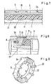
- FIG. 1 show the elements of an arrangement with an elastomer sealing ring 4 and a support ring 3.
- the sealing ring and the support ring are installed in a radial groove of the cylindrical outer part 8.
- the sealing ring forms, together with the surface of the shaft 5, the sliding sealing surface 45.
- the sealing ring first lies against the projections 32 of the support ring 3.
- the sections of the sealing ring lying between the projections bend axially.
- the sealing ring including the pressure-side edge 451 of the sliding sealing surface, assumes a wavy shape.
- the sealing ring lies on the surface of the support ring over the entire circumference, as a result of which its maximum deformation is limited and its shape can be defined at maximum deformation.
- projections 34 are attached, into which pins 6 engage to prevent rotation between the outer part and the support ring.
- the anti-rotation lock between the sealing ring and the support ring takes place automatically in that a positive connection is created as a result of the deformation-related interlocking of the sealing ring and the support ring.
- the pressure-side projections 32 are wave-shaped and the projections 34 are prismatic.
- 3 shows an arrangement in which the sealing ring 4 and the support ring 3 are arranged in a groove in the shaft, the sliding sealing surface 48 being formed by a peripheral surface of the cylindrical outer part 8.
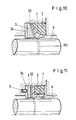
- Figures 4 to 6 show the elements of an arrangement with a sealing ring 1 made of plastic, an elastomer ring 2 as a clamping ring and secondary seal and a support ring 3.
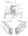
- Fig. 4 shows the arrangement as a shaft seal in longitudinal section, the sealing ring, the clamping ring and the Support ring are installed in a radial groove of the cylindrical outer part 8.
- the sealing edge 11 of the sealing ring 1 forms, together with the surface of the shaft 5, the sliding sealing surface 15. Under the action of the pressure p to be sealed, the sealing ring initially rests on the projections 32 of the support ring 3.
- the clamping ring 2 also bears against the projections 32.
- the parts of the sealing ring and the tension ring lying between the projections 32 bend in the direction of the shaft axis of rotation.
- the sealing ring including the pressure-side edge 151 a wavy shape on its sliding sealing surface.
- projections 34 are attached, into which projections 6 engage in order to prevent rotation between the outer part and the support ring.
- the anti-rotation lock between the sealing ring and the support ring takes place automatically in that a positive connection is created as a result of the deformation-related interlocking of the sealing ring and the support ring.
- FIG. 5 shows a perspective view of a support ring according to the invention, in which, for example, the pressure-side projections 32 are prismatic with radially directed longitudinal edges.
- the opposite projections 34 are, for example, of the same design as the projections 32, so that here the support ring is mirror-symmetrical with respect to its central plane perpendicular to the shaft axis.
- the sealing ring 1 with its sealing edge 11 is tensioned by a 0-ring 2 and sealed secondary.
- FIG. 6 shows a detail from a representation of the sealing arrangement according to FIGS. 4 and 5, which is developed in the plane.
- the deformation-related anchoring of the bent sealing ring 1 on the edges 36 of the prism-shaped projections 32 can be clearly seen.
- the ring web 35 of the support ring 3 begins to bend between the projections 34 as soon as the bent sealing ring 1 is supported on the parts of the surface 31 lying between the projections 32 at a specific pressure p. With increasing pressure, the deformation of the sealing ring can therefore increase even more, but more slowly because of the increased resistance to deformation due to the support ring.
- Fig. 7 shows a detail of a plane view of the sealing arrangement according to the invention with the sealing ring 1 and the support ring 3.
- the sealing ring rests on the prismatic projections 32 of the support ring while it is supported on prismatic projections 34 on a wall from which Protruding protrusions 6 to prevent rotation.
- the projections 32 and 34 are each offset by half a division on the circumference, so that here the deflection of the sealing ring no longer increases when it touches the surface 31 of the support ring, but the deflection between the projections 32 increases Pressure increases less because the area 35 of the ring land between the projections 34 is flexible.
- Figures 8 and 9 show the elements of an arrangement of the shaft seal according to the invention with a sealing ring 1 in the form of a conical disc spring with the sealing edge 11, a clamping ring 2 as an O-ring made of elastomer and a support ring 3 with projections 32 protruding from its conical end face 31 On its end face facing away from the pressure, the support ring has projections 34 into which pins 6 engage.
- Fig. 9 shows the conical support ring of the arrangement of FIG. 8 in a perspective view.
- Figures 10 and 11 show further variants of the shaft seal according to the invention, each with the sealing rings 1, the clamping rings 2, the support rings 3 with the projections 32 and 34 and the pins 6 engaging in the gaps between the projections 34 to prevent rotation in cross-section each from a radially or approximately radially extending wing, the extension of which leads approximately to the sliding sealing surface 151 and which lies against the support ring and changes the shape of the sliding sealing surface due to its deformation, and from a wing directed more axially towards the pressure side, onto which the clamping ring 2 mainly acts.
- FIG. 12 shows an optimal design of the shaft seal according to the invention with regard to friction and lubrication.
- the sealing ring 1 made of plastic has a sealing edge 11 which is as close as possible to its end face 17 facing away from the pressure p.
- the clamping ring 2 is an X-ring made of elastomer.
- the support ring 3 with its end projections 32 is connected to the housing 8 in a rotationally secured manner and arranged axially so that the end face 81 of the housing groove, on which the clamping ring rests on its pressure-facing end face, is offset axially by the dimension "T" relative to the pressure-facing end face 33 of the sealing ring is offset.
- the radial force transmitted from the clamping ring to the sealing ring can be determined to the size that is just necessary in terms of sealing technology, which on the other hand results in the smallest possible frictional force between the sealing ring and rotating shaft.
- the clamping ring ensures sufficient preload in the depressurized state.
- the pressurized state there is an extensive balance between the force exerted radially inward on the sealing ring by the force and the force acting radially outward from the medium pressure within the annular space 153 between the sealing ring and shaft.
- the annular space 153 between the sealing ring and shaft 5 is by means of at least one axial groove 154 connected in the sealing ring to the space to be sealed and thus always subjected to the pressure p, which relieves the sealing ring radially. Furthermore, at least one radial groove 155 is provided on the pressure-facing end face of the sealing ring in order to allow the pressure p to be sealed to also reach the groove space in front of the clamping ring. This ensures that the clamping ring is always loaded with the pressure p in full even when the pressure changes quickly.
- FIG. 13 shows a further embodiment of a shaft seal according to the invention in which, in addition to the generation of a ripple of the sliding sealing surface that increases as a function of pressure, the principle of the partial relief of the sealing edge 11 just explained from the effect of the pressure to be sealed is used. Both effects together result in an optimal sealing behavior with the lowest possible friction and thus practically no wear.
- FIG. 13 shows how a rotating shaft is sealed with a PTFE sealing edge ring 1, which is usually used as a hydraulic seal, with almost no leakage and with the least amount of friction, by the sealing ring being supported axially on the projections 32 of a support ring 3.
- the additional spacer ring 9 here causes a support of the rear side of the clamping ring which is offset axially by the dimension “T” and is designed here, for example, as an 0-ring. There is so much radial play between the sealing ring and the spacer ring that no radial force can be transmitted from the spacer ring to the sealing ring. As a result, as well as by the choice of the dimension "T", it is up to the seal designer to choose the pressure-dependent increasing radial pressure on the sealing edge 11 so that leakage on the one hand and frictional performance of the seal on the other are optimally coordinated with one another in accordance with the special task.
- the projections which, according to the invention, serve to axially support the sealing ring.
- the projections can be attached to a support ring or to the sealing ring.
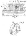
- Fig. 15 shows an arrangement with the sealing ring 1, the clamping ring 2, the support ring 3 with its shoulders 321 and 322. These parts are arranged in the sleeve 81, wherein on the side of the sealing ring facing the fluid to be sealed, the pump ring 83 with the Axis oblique grooves 831 and the return grooves 832 is arranged.
- the pump ring is secured by bending the edge 811 of the sleeve 81.
- the sleeve is sealed off from the housing 8 by the elastomer seal 82.
- the sleeve 81 has a plurality of elastic projections 84 distributed over the circumference and is supported axially on the housing via these, pins 85 which engage between the projections 84 , prevent relative rotation between the sleeve and the housing.
- 16 shows a perspective view of the pump ring 83 with its oblique grooves 831 and its axially arranged return grooves 832.
- FIG. 17 shows a sealing arrangement with the sealing ring 1, the tension ring 2, the support ring 3 and its shoulders 321, installed in the sleeve 81 and secured against slipping out on the high pressure side by the disk 86 and the snap ring 87.
- the sleeve 81 is supported in the housing 89 via the elastomer sealing ring 82 both axially and radially elastically.
- the seal 82 simultaneously seals the sleeve from the housing.
- a pin 85 engages radially in recesses 84 of the sleeve 81 and thus prevents relative rotation between the sleeve and the housing.
- FIG. 18 shows a perspective view of the support ring of the arrangement according to FIG. 17 with the projections 32 according to the invention and the heels 321 attached to both the projections and to the walls 31 of the support ring lying between the projections.
- These heels engage under corresponding edges 100 or protruding edges Surfaces of the sealing ring and thus prevent the sealing ring from sliding radially under the influence of the pressure difference or due to oblique bending during the deformation.
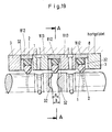
- FIG. 19 shows the arrangement of a rotary feedthrough with a total of 3 sealing systems of the type according to the invention.
- the system is constructed from individual ring-like bodies, all of which are connected to the housing 8 by brazing.
- the groove receiving the sealing ring 1 and the clamping ring 2 is formed by the support ring 3, the outer ring 812 and the ring 813.
- This rotary feedthrough system containing two separate fluid channels is mirror-symmetrical to the center plane A-A.
- the projections 32 of the two support rings 813 are offset in the circumferential direction by half a division of the projections 32 from one another.
- the spacing a of the projections in the central sealing groove is smaller than the axial width b of the seal 1, as a result of which a ripple in the circumference of the seal arises even when it is installed without pressure.
- FIGS. 20-22 finally show an embodiment of the shaft seal according to the invention with a sealing ring 1, a clamping ring 2, a support ring 3 and a sleeve 81.
- This sealing arrangement is preferably of the same construction as a radial shaft sealing ring, the elastomer seal 82 statically sealing the sleeve relative to the housing 8 .
- the sleeve and support ring are designed as drawn parts made of sheet metal and are integrally connected to one another, preferably by means of spot welding 311.
- the projections 32 on the support ring and the projections 815 on the inner end face of the sleeve are also stamped in during the manufacturing process of the sheet metal parts.
- the protrusions 32 and 815 are each one-half pitch in Arranged circumferentially offset from one another, such that the center of a projection 815 of the sleeve lies between two projections 32.
- the axial distance "a" between the projections 32 and 815 is smaller than the axial width "b" of the sealing ring, as a result of which a wavy shape seen in the circumferential direction is impressed on the sealing ring during installation.
Landscapes
- Engineering & Computer Science (AREA)
- General Engineering & Computer Science (AREA)
- Mechanical Engineering (AREA)
- Physics & Mathematics (AREA)
- Fluid Mechanics (AREA)
- Sealing Devices (AREA)
- Structures Of Non-Positive Displacement Pumps (AREA)
Priority Applications (1)
| Application Number | Priority Date | Filing Date | Title |
|---|---|---|---|
| AT85108671T ATE38418T1 (de) | 1984-07-11 | 1985-07-11 | Wellendichtung. |
Applications Claiming Priority (4)
| Application Number | Priority Date | Filing Date | Title |
|---|---|---|---|
| DE3425431A DE3425431C1 (de) | 1984-07-11 | 1984-07-11 | Wellendichtung |
| DE3425431 | 1984-07-11 | ||
| DE3502799 | 1985-01-29 | ||
| DE19853502799 DE3502799A1 (de) | 1984-07-11 | 1985-01-29 | Wellendichtung |
Publications (2)
| Publication Number | Publication Date |
|---|---|
| EP0170928A1 EP0170928A1 (de) | 1986-02-12 |
| EP0170928B1 true EP0170928B1 (de) | 1988-11-02 |
Family
ID=25822793
Family Applications (1)
| Application Number | Title | Priority Date | Filing Date |
|---|---|---|---|
| EP85108671A Expired EP0170928B1 (de) | 1984-07-11 | 1985-07-11 | Wellendichtung |
Country Status (4)
| Country | Link |
|---|---|
| US (1) | US4729569A (da) |
| EP (1) | EP0170928B1 (da) |
| DE (2) | DE3502799A1 (da) |
| DK (1) | DK314685A (da) |
Cited By (1)
| Publication number | Priority date | Publication date | Assignee | Title |
|---|---|---|---|---|
| DE8907606U1 (de) * | 1989-06-21 | 1990-10-18 | Feodor Burgmann Dichtungswerke Gmbh & Co, 8190 Wolfratshausen | Ringdichtung für den Kugelkörper eines im Zylinderkopf eines Verbrennungsmotors gelagerten Kugeldrehschiebers |
Families Citing this family (50)
| Publication number | Priority date | Publication date | Assignee | Title |
|---|---|---|---|---|
| DE3502799A1 (de) * | 1984-07-11 | 1986-07-31 | Martin Merkel GmbH & Co KG, 2102 Hamburg | Wellendichtung |
| DE3616689C1 (de) * | 1986-05-16 | 1987-11-19 | Mueller Heinz Konrad Prof Dr I | Dichtung |
| DE3642721A1 (de) * | 1986-12-13 | 1988-06-16 | Lechler Elring Dichtungswerke | Ringdichtungsanordnung |
| DE3705448A1 (de) * | 1987-02-20 | 1988-09-01 | Blohm Voss Ag | Dichtungssytem |
| DE3716862A1 (de) * | 1987-05-20 | 1988-12-15 | Blohm Voss Ag | Anordnung zur abdichtung von rotierenden wellen |
| DE4213996A1 (de) * | 1992-04-29 | 1993-11-04 | Goetze Ag | Wellendichtring |
| DE4337813C2 (de) * | 1993-11-05 | 1996-04-18 | Fichtel & Sachs Ag | Schwenkmotor |
| US5941534A (en) * | 1994-10-12 | 1999-08-24 | Honda Giken Kogyo Kabushiki Kaisha | Hydraulic seal system |
| JP3860283B2 (ja) * | 1996-06-26 | 2006-12-20 | Nok株式会社 | 密封装置 |
| US6340160B1 (en) * | 1997-09-30 | 2002-01-22 | Gilbert W. Younger | System for sealing relatively movable elements |
| EP2163795B1 (en) * | 2000-05-02 | 2012-05-02 | Halliburton Energy Services, Inc. | Seal assembly for limiting the movement of a seal within a seal housing |
| EP1394452A4 (en) * | 2001-06-04 | 2007-09-19 | Nok Corp | SEAL DEVICE |
| EP1308654A1 (en) * | 2001-10-31 | 2003-05-07 | Kalsi Engineering, Inc. | Hydrodynamic packing assembly |
| DE10215311A1 (de) * | 2002-04-08 | 2003-11-06 | Hammelmann Paul Maschf | Dichtungseinrichtung |
| US20050046114A1 (en) * | 2003-08-27 | 2005-03-03 | Bohner Stephan Ernst | Rotary seal member, assembly and methods for a hydraulic rotary swivel |
| US6896110B2 (en) * | 2003-09-25 | 2005-05-24 | Tenneco Automotive Operating Company Inc. | Temperature compensated dual acting slip |
| DE202004007290U1 (de) * | 2004-05-07 | 2005-09-15 | Viega Gmbh & Co Kg | Dichtelement |
| DE202004007291U1 (de) * | 2004-05-07 | 2005-09-15 | Viega Gmbh & Co Kg | Pressverbindungsanordnung |
| RU2400662C2 (ru) | 2005-03-22 | 2010-09-27 | Колси Энджиниринг, Инк. | Гидродинамическое уплотнение вращающегося соединения |
| CA2601655C (en) * | 2005-03-28 | 2013-09-24 | Kalsi Engineering, Inc. | Composite, high temperature, dynamic seal and method of making same |
| WO2007011883A2 (en) * | 2005-07-18 | 2007-01-25 | Kalsi Engineering, Inc. | Filled hydrodynamic seal with contact pressure control, anti-rotation and filler retention |
| JP4579110B2 (ja) * | 2005-09-07 | 2010-11-10 | 三菱電線工業株式会社 | 回転軸シール |
| US7770898B2 (en) | 2006-01-04 | 2010-08-10 | Kalsi Engineering, Inc. | Stabilizing geometry for hydrodynamic rotary seals |
| US8550467B2 (en) * | 2006-03-22 | 2013-10-08 | Kalsi Engineering, Inc. | Rotary seal with improved film distribution |
| DE102007016896A1 (de) * | 2007-04-10 | 2008-10-16 | Jost-Werke Gmbh | Kugelkupplung mit relativbeweglich aufgenommener Dichtung |
| US20090108538A1 (en) * | 2007-10-24 | 2009-04-30 | Freudenberg-Nok General Partnership | Two-Component Seal With Integral Locking Feature To Prevent Relative Rotation |
| DE102008012676A1 (de) * | 2008-03-05 | 2009-09-17 | Hunger Maschinen Gmbh | Drehdurchführung |
| US9109703B2 (en) | 2010-02-11 | 2015-08-18 | Kalsi Engineering, Inc. | Hydrodynamic backup ring |
| US9845879B2 (en) | 2009-11-30 | 2017-12-19 | Kalsi Engineering, Inc. | High pressure dynamic sealing arrangement |
| US9429238B2 (en) | 2009-11-30 | 2016-08-30 | Kalsi Engineering, Inc. | Dynamic backup ring assembly |
| DE102010001345B4 (de) * | 2010-01-28 | 2013-09-19 | Trelleborg Sealing Solutions Germany Gmbh | Drehdurchführung |
| JP5598222B2 (ja) * | 2010-09-30 | 2014-10-01 | 株式会社アドヴィックス | 軸シール装置とそれを用いたポンプ装置及びブレーキ液圧制御装置 |
| US20120223485A1 (en) * | 2011-03-04 | 2012-09-06 | Jeong-Jung Heo | Link seal for track of tracked vehicles |
| ITMI20111739A1 (it) * | 2011-09-27 | 2013-03-28 | Freni Brembo Spa | Dispositivo di arretramento di un pistone |
| US20140037488A1 (en) * | 2012-07-31 | 2014-02-06 | John Stewart Glen | Vane-type Compressors and Expanders with Minimal Internal Energy Losses |
| DE102013217581A1 (de) * | 2013-09-04 | 2015-03-05 | MTU Aero Engines AG | Dichtungsanordnung in einer axialen Strömungsmaschine |
| US9617822B2 (en) | 2013-12-03 | 2017-04-11 | Baker Hughes Incorporated | Compliant seal for irregular casing |
| DE102014216268A1 (de) * | 2014-08-15 | 2016-02-18 | Trelleborg Sealing Solutions Germany Gmbh | Dichtungsanordnung mit Dämpfungsglied |
| US10344862B2 (en) * | 2015-01-12 | 2019-07-09 | Rolls-Royce Corporation | Shaft coupling seal assembly |
| DE102017207091A1 (de) * | 2016-06-30 | 2018-01-04 | Robert Bosch Gmbh | Ventil zum Zumessen eines Fluids, Anschlussstück für ein Ventil und Brennstoffeinspritzanlage |
| DE102016218239A1 (de) * | 2016-09-22 | 2018-03-22 | MTU Aero Engines AG | Dichtungsanordnung für ein Turbinenzwischengehäuse einer Gasturbine |
| US10330203B2 (en) | 2017-01-06 | 2019-06-25 | Kalsi Engineering Inc. | High pressure dynamic sealing device |
| DE102017204374A1 (de) * | 2017-03-16 | 2018-09-20 | Trelleborg Sealing Solutions Germany Gmbh | Dichtungsanordnung |
| US10302200B2 (en) | 2017-05-16 | 2019-05-28 | Kalsi Engineering, Inc. | Seal for bi-directional rotation and pressure |
| AT16131U1 (de) * | 2017-06-09 | 2019-02-15 | Engel Austria Gmbh | Vorrichtung zum Abdichten einer Welle für eine Formgebungsmaschine |
| US11668399B2 (en) | 2018-05-15 | 2023-06-06 | Kalsi Engineering, Inc. | Rotary seal and method of making same |
| US11300208B2 (en) * | 2018-11-26 | 2022-04-12 | Kalsi Engineering, Inc. | Seal assembly with anti-rotation and stability features |
| US11125336B2 (en) * | 2019-06-17 | 2021-09-21 | Freudenberg-Nok General Partnership | Self energized seal |
| US20230349465A1 (en) * | 2022-05-02 | 2023-11-02 | Ariel Corporation | Laterally moveable compressor piston rod lip seal assembly |
| US12560210B2 (en) * | 2023-07-18 | 2026-02-24 | Bendix Commercial Vehicle Systems Llc | Air disc brake system with caliper retraction and methods for the use and assembly thereof |
Family Cites Families (16)
| Publication number | Priority date | Publication date | Assignee | Title |
|---|---|---|---|---|
| US1307901A (en) * | 1919-06-24 | fariand and l f | ||
| CH27569A (de) * | 1902-12-19 | 1904-01-31 | Sulzer Ag | Einrichtung zur Abdichtung zylindrischer, den Abschluß eines Druckraumes bildender Drehkörper |
| US1770509A (en) * | 1927-02-23 | 1930-07-15 | Wallace C Chambers | Flexible metallic packing |
| FR652389A (fr) * | 1928-04-07 | 1929-03-07 | Obturateur pour boîtes d'essieux et paliers d'arbres animés d'un mouvement de rotation dans les deux sens | |
| GB559736A (en) * | 1942-11-02 | 1944-03-02 | Pyrene Co Ltd | Improvements in gland packings |
| DE903878C (de) * | 1951-12-25 | 1954-02-11 | Iaweseria Ag | Stopfbuchsendichtung |
| GB762958A (en) * | 1953-09-25 | 1956-12-05 | Bristol Aeroplane Co Ltd | Improvements in or relating to sealing means for preventing or reducing the escape of a liquid through a gap between a pair of relatively rotating elements |
| FR1267218A (fr) * | 1960-06-07 | 1961-07-21 | Joint Francais | Joint torique d'étanchéité |
| FR82269E (fr) * | 1962-06-06 | 1964-01-17 | Joint Francais | Joint torique d'étanchéité |
| DE2206461C2 (de) * | 1972-02-11 | 1983-11-17 | Fa. Carl Freudenberg, 6940 Weinheim | Radiallippendichtung |
| US4336945A (en) * | 1977-03-18 | 1982-06-29 | Cr Industries | Sinuous seal with auxiliary excluder lips |
| US4175475A (en) * | 1977-11-30 | 1979-11-27 | General Motors Corporation | Worm thread seal for steering gear |
| US4323287A (en) * | 1979-10-03 | 1982-04-06 | The Torrington Company | Bearing seal |
| DE3207327A1 (de) * | 1982-03-01 | 1983-09-08 | Heinz Konrad Prof. Dr.-Ing. 7050 Waiblingen Müller | Wellendichtung |
| AU566210B2 (en) * | 1983-05-19 | 1987-10-15 | Bw/Ip International, Inc. | Mechanical seal |
| DE3502799A1 (de) * | 1984-07-11 | 1986-07-31 | Martin Merkel GmbH & Co KG, 2102 Hamburg | Wellendichtung |
-
1985
- 1985-01-29 DE DE19853502799 patent/DE3502799A1/de not_active Withdrawn
- 1985-07-10 DK DK314685A patent/DK314685A/da not_active Application Discontinuation
- 1985-07-11 EP EP85108671A patent/EP0170928B1/de not_active Expired
- 1985-07-11 US US06/754,516 patent/US4729569A/en not_active Expired - Fee Related
- 1985-07-11 DE DE8585108671T patent/DE3566027D1/de not_active Expired
Cited By (1)
| Publication number | Priority date | Publication date | Assignee | Title |
|---|---|---|---|---|
| DE8907606U1 (de) * | 1989-06-21 | 1990-10-18 | Feodor Burgmann Dichtungswerke Gmbh & Co, 8190 Wolfratshausen | Ringdichtung für den Kugelkörper eines im Zylinderkopf eines Verbrennungsmotors gelagerten Kugeldrehschiebers |
Also Published As
| Publication number | Publication date |
|---|---|
| DE3566027D1 (en) | 1988-12-08 |
| DK314685D0 (da) | 1985-07-10 |
| DK314685A (da) | 1986-01-12 |
| EP0170928A1 (de) | 1986-02-12 |
| US4729569A (en) | 1988-03-08 |
| DE3502799A1 (de) | 1986-07-31 |
Similar Documents
| Publication | Publication Date | Title |
|---|---|---|
| EP0170928B1 (de) | Wellendichtung | |
| DE2939945C2 (da) | ||
| EP0268624B1 (de) | Dichtungsanordnung | |
| DE60207663T2 (de) | Bürstendichtung und Bürstendichtungsanordnung | |
| EP0139965B1 (de) | Dichtring für Kolbenstangen | |
| EP0980998B1 (de) | Radialwellendichtring | |
| DE3320063C2 (da) | ||
| DE112018004245B4 (de) | Dichtring | |
| DE2756403C3 (de) | Dichtung | |
| DE20121487U1 (de) | Wellendichtring | |
| DE2949839C2 (de) | Dichtring | |
| DE19509771C1 (de) | Dichtring | |
| DE3213809C2 (de) | Kassettendichtung | |
| EP0130237A1 (de) | Wellendichtring | |
| DE3425431C1 (de) | Wellendichtung | |
| EP0798498B1 (de) | Radialwellendichtring mit drehrichtungsunabhängiger Förderwirkung | |
| DE3217118C1 (de) | Dichtungsanordnung für Wellen | |
| DE2305826A1 (de) | Dichtungsringanordnung | |
| DE4222852A1 (de) | Wälzlagereinheit | |
| DE3434421A1 (de) | Selbsttaetig rueckstellbare bremsbacke fuer teilbelag-scheibenbremsen | |
| DE3337033A1 (de) | Achs- oder wellendichtung | |
| DE3323948C2 (da) | ||
| DE3208396C1 (de) | Kolbenring | |
| DE60302547T2 (de) | Führungskonfiguration für drucklageranordnung | |
| DE3431990A1 (de) | Manschette fuer dichtungen, vorzugsweise fuer radialwellendichtringe |
Legal Events
| Date | Code | Title | Description |
|---|---|---|---|
| PUAI | Public reference made under article 153(3) epc to a published international application that has entered the european phase |
Free format text: ORIGINAL CODE: 0009012 |
|
| AK | Designated contracting states |
Designated state(s): AT CH DE FR GB IT LI SE |
|
| 16A | New documents despatched to applicant after publication of the search report | ||
| 17P | Request for examination filed |
Effective date: 19860502 |
|
| 17Q | First examination report despatched |
Effective date: 19870721 |
|
| GRAA | (expected) grant |
Free format text: ORIGINAL CODE: 0009210 |
|
| AK | Designated contracting states |
Kind code of ref document: B1 Designated state(s): AT CH DE FR GB IT LI SE |
|
| REF | Corresponds to: |
Ref document number: 38418 Country of ref document: AT Date of ref document: 19881115 Kind code of ref document: T |
|
| REF | Corresponds to: |
Ref document number: 3566027 Country of ref document: DE Date of ref document: 19881208 |
|
| ITF | It: translation for a ep patent filed | ||
| GBT | Gb: translation of ep patent filed (gb section 77(6)(a)/1977) | ||
| ET | Fr: translation filed | ||
| PLBE | No opposition filed within time limit |
Free format text: ORIGINAL CODE: 0009261 |
|
| STAA | Information on the status of an ep patent application or granted ep patent |
Free format text: STATUS: NO OPPOSITION FILED WITHIN TIME LIMIT |
|
| 26N | No opposition filed | ||
| ITTA | It: last paid annual fee | ||
| EAL | Se: european patent in force in sweden |
Ref document number: 85108671.0 |
|
| REG | Reference to a national code |
Ref country code: FR Ref legal event code: TP |
|
| REG | Reference to a national code |
Ref country code: GB Ref legal event code: 732E |
|
| REG | Reference to a national code |
Ref country code: FR Ref legal event code: TP Ref country code: FR Ref legal event code: CD Ref country code: FR Ref legal event code: CA |
|
| REG | Reference to a national code |
Ref country code: GB Ref legal event code: 732E |
|
| REG | Reference to a national code |
Ref country code: GB Ref legal event code: IF02 |
|
| PGFP | Annual fee paid to national office [announced via postgrant information from national office to epo] |
Ref country code: GB Payment date: 20030625 Year of fee payment: 19 |
|
| PGFP | Annual fee paid to national office [announced via postgrant information from national office to epo] |
Ref country code: DE Payment date: 20030711 Year of fee payment: 19 |
|
| PGFP | Annual fee paid to national office [announced via postgrant information from national office to epo] |
Ref country code: SE Payment date: 20030716 Year of fee payment: 19 |
|
| PGFP | Annual fee paid to national office [announced via postgrant information from national office to epo] |
Ref country code: FR Payment date: 20030723 Year of fee payment: 19 |
|
| PGFP | Annual fee paid to national office [announced via postgrant information from national office to epo] |
Ref country code: AT Payment date: 20030729 Year of fee payment: 19 |
|
| PGFP | Annual fee paid to national office [announced via postgrant information from national office to epo] |
Ref country code: CH Payment date: 20030731 Year of fee payment: 19 |
|
| PG25 | Lapsed in a contracting state [announced via postgrant information from national office to epo] |
Ref country code: GB Free format text: LAPSE BECAUSE OF NON-PAYMENT OF DUE FEES Effective date: 20040711 Ref country code: AT Free format text: LAPSE BECAUSE OF NON-PAYMENT OF DUE FEES Effective date: 20040711 |
|
| PG25 | Lapsed in a contracting state [announced via postgrant information from national office to epo] |
Ref country code: SE Free format text: LAPSE BECAUSE OF NON-PAYMENT OF DUE FEES Effective date: 20040712 |
|
| PG25 | Lapsed in a contracting state [announced via postgrant information from national office to epo] |
Ref country code: LI Free format text: LAPSE BECAUSE OF NON-PAYMENT OF DUE FEES Effective date: 20040731 Ref country code: CH Free format text: LAPSE BECAUSE OF NON-PAYMENT OF DUE FEES Effective date: 20040731 |
|
| PG25 | Lapsed in a contracting state [announced via postgrant information from national office to epo] |
Ref country code: DE Free format text: LAPSE BECAUSE OF NON-PAYMENT OF DUE FEES Effective date: 20050201 |
|
| EUG | Se: european patent has lapsed | ||
| GBPC | Gb: european patent ceased through non-payment of renewal fee |
Effective date: 20040711 |
|
| REG | Reference to a national code |
Ref country code: CH Ref legal event code: PL |
|
| PG25 | Lapsed in a contracting state [announced via postgrant information from national office to epo] |
Ref country code: FR Free format text: LAPSE BECAUSE OF NON-PAYMENT OF DUE FEES Effective date: 20050331 |
|
| REG | Reference to a national code |
Ref country code: FR Ref legal event code: ST |