EP0170928B1 - Shaft seal - Google Patents
Shaft seal Download PDFInfo
- Publication number
- EP0170928B1 EP0170928B1 EP85108671A EP85108671A EP0170928B1 EP 0170928 B1 EP0170928 B1 EP 0170928B1 EP 85108671 A EP85108671 A EP 85108671A EP 85108671 A EP85108671 A EP 85108671A EP 0170928 B1 EP0170928 B1 EP 0170928B1
- Authority
- EP
- European Patent Office
- Prior art keywords
- ring
- projections
- seal
- sealing
- fact
- Prior art date
- Legal status (The legal status is an assumption and is not a legal conclusion. Google has not performed a legal analysis and makes no representation as to the accuracy of the status listed.)
- Expired
Links
- 238000007789 sealing Methods 0.000 claims description 206
- 229920001971 elastomer Polymers 0.000 claims description 12
- 239000000806 elastomer Substances 0.000 claims description 12
- 239000004033 plastic Substances 0.000 claims description 8
- 239000000463 material Substances 0.000 claims description 4
- 239000002184 metal Substances 0.000 claims description 4
- 230000013011 mating Effects 0.000 claims 1
- 230000000694 effects Effects 0.000 description 7
- 239000012530 fluid Substances 0.000 description 7
- 238000009434 installation Methods 0.000 description 6
- 230000001050 lubricating effect Effects 0.000 description 6
- 238000005452 bending Methods 0.000 description 5
- 238000005516 engineering process Methods 0.000 description 4
- 239000007788 liquid Substances 0.000 description 4
- 230000015572 biosynthetic process Effects 0.000 description 3
- 238000010276 construction Methods 0.000 description 3
- 230000001419 dependent effect Effects 0.000 description 3
- 238000005461 lubrication Methods 0.000 description 3
- 238000004519 manufacturing process Methods 0.000 description 3
- 230000002093 peripheral effect Effects 0.000 description 3
- 125000006850 spacer group Chemical group 0.000 description 3
- 230000003068 static effect Effects 0.000 description 2
- 238000004873 anchoring Methods 0.000 description 1
- 230000009286 beneficial effect Effects 0.000 description 1
- 238000005219 brazing Methods 0.000 description 1
- 238000001816 cooling Methods 0.000 description 1
- 239000012809 cooling fluid Substances 0.000 description 1
- 239000000110 cooling liquid Substances 0.000 description 1
- 238000010438 heat treatment Methods 0.000 description 1
- 239000000314 lubricant Substances 0.000 description 1
- 239000004810 polytetrafluoroethylene Substances 0.000 description 1
- 229920001343 polytetrafluoroethylene Polymers 0.000 description 1
- 230000036316 preload Effects 0.000 description 1
- 238000003825 pressing Methods 0.000 description 1
- 230000000630 rising effect Effects 0.000 description 1
- 238000003466 welding Methods 0.000 description 1
Images


Classifications
-
- F—MECHANICAL ENGINEERING; LIGHTING; HEATING; WEAPONS; BLASTING
- F16—ENGINEERING ELEMENTS AND UNITS; GENERAL MEASURES FOR PRODUCING AND MAINTAINING EFFECTIVE FUNCTIONING OF MACHINES OR INSTALLATIONS; THERMAL INSULATION IN GENERAL
- F16J—PISTONS; CYLINDERS; SEALINGS
- F16J15/00—Sealings
- F16J15/16—Sealings between relatively-moving surfaces
- F16J15/164—Sealings between relatively-moving surfaces the sealing action depending on movements; pressure difference, temperature or presence of leaking fluid
-
- F—MECHANICAL ENGINEERING; LIGHTING; HEATING; WEAPONS; BLASTING
- F16—ENGINEERING ELEMENTS AND UNITS; GENERAL MEASURES FOR PRODUCING AND MAINTAINING EFFECTIVE FUNCTIONING OF MACHINES OR INSTALLATIONS; THERMAL INSULATION IN GENERAL
- F16J—PISTONS; CYLINDERS; SEALINGS
- F16J15/00—Sealings
- F16J15/16—Sealings between relatively-moving surfaces
- F16J15/32—Sealings between relatively-moving surfaces with elastic sealings, e.g. O-rings
- F16J15/3204—Sealings between relatively-moving surfaces with elastic sealings, e.g. O-rings with at least one lip
- F16J15/3216—Sealings between relatively-moving surfaces with elastic sealings, e.g. O-rings with at least one lip supported in a direction parallel to the surfaces
-
- F—MECHANICAL ENGINEERING; LIGHTING; HEATING; WEAPONS; BLASTING
- F16—ENGINEERING ELEMENTS AND UNITS; GENERAL MEASURES FOR PRODUCING AND MAINTAINING EFFECTIVE FUNCTIONING OF MACHINES OR INSTALLATIONS; THERMAL INSULATION IN GENERAL
- F16J—PISTONS; CYLINDERS; SEALINGS
- F16J15/00—Sealings
- F16J15/16—Sealings between relatively-moving surfaces
- F16J15/32—Sealings between relatively-moving surfaces with elastic sealings, e.g. O-rings
- F16J15/324—Arrangements for lubrication or cooling of the sealing itself
-
- F—MECHANICAL ENGINEERING; LIGHTING; HEATING; WEAPONS; BLASTING
- F16—ENGINEERING ELEMENTS AND UNITS; GENERAL MEASURES FOR PRODUCING AND MAINTAINING EFFECTIVE FUNCTIONING OF MACHINES OR INSTALLATIONS; THERMAL INSULATION IN GENERAL
- F16J—PISTONS; CYLINDERS; SEALINGS
- F16J15/00—Sealings
- F16J15/16—Sealings between relatively-moving surfaces
- F16J15/32—Sealings between relatively-moving surfaces with elastic sealings, e.g. O-rings
- F16J15/3244—Sealings between relatively-moving surfaces with elastic sealings, e.g. O-rings with hydrodynamic pumping action
-
- F—MECHANICAL ENGINEERING; LIGHTING; HEATING; WEAPONS; BLASTING
- F16—ENGINEERING ELEMENTS AND UNITS; GENERAL MEASURES FOR PRODUCING AND MAINTAINING EFFECTIVE FUNCTIONING OF MACHINES OR INSTALLATIONS; THERMAL INSULATION IN GENERAL
- F16L—PIPES; JOINTS OR FITTINGS FOR PIPES; SUPPORTS FOR PIPES, CABLES OR PROTECTIVE TUBING; MEANS FOR THERMAL INSULATION IN GENERAL
- F16L27/00—Adjustable joints, Joints allowing movement
- F16L27/08—Adjustable joints, Joints allowing movement allowing adjustment or movement only about the axis of one pipe
- F16L27/087—Joints with radial fluid passages
Definitions
- the invention relates to a shaft seal with an elastic sealing ring acted upon by the pressure to be sealed, the low-pressure side end face of which is supported by a plurality of projections, in such a way that its sealing surface interacting with a cylindrical counter sliding surface has a wave-like course.
- shaft seals are often limited due to the frictional heat generated on the sealing surfaces. In the case of seals with pressure-dependent sealing surface pressure, a relatively high friction loss occurs when sealing under high pressure. If the seals also consist of materials with low thermal conductivity, there is a risk that the temperature at the sealing surfaces that is beneficial for the material will be exceeded and the seal will fail prematurely.
- a measure known in sealing technology for reducing the friction is the targeted generation of a lubricating film that separates the sliding sealing surfaces and fills the sealing gap.
- the liquid to be sealed which acts as a lubricant in the sealing gap, can considerably reduce the coefficient of friction.
- the wear of the sliding sealing surfaces can be reduced or almost completely avoided by means of dynamic lubricating film formation.
- the object underlying the invention is therefore to create a seal of the type mentioned, which avoids these disadvantages.
- the solution according to the invention consists in that the projections are arranged on a support ring and the sealing ring cross section is dimensioned for wave-like deformation under the action of the pressure to be sealed.
- the high-pressure side sealing surface edge formed by parts of this cross section is also deformed in a desired manner, so that the conditions for the formation of a hydrodynamic lubricating film are improved.
- the projections act as an anti-twist device.
- the inventive idea is preferably realized in that a support ring is arranged on the low pressure side, which has wavy projections on its side surface facing the sealing ring.
- the steepness of the waves, seen in the circumferential direction, can be made unequal on the rising and falling wave flanks.
- the designer can therefore selectively influence the drag effect and thus the formation of the lubricating film with a view to the one to be sealed Control pressure.
- the towing speed component from the space to be sealed into the sealing gap can be smaller than the component that tows the liquid in the gap back into the high-pressure space. Because of the asymmetry of the pressure profile in the sealing gap, the best dynamic sealing effect results in this case.
- the projections of the support ring can also be designed according to the invention in such a way that the sealing ring only rests at low pressure on the edges or the front surfaces of the projections and only with increasing pressure does the sealing ring contact other parts of the end face of the support ring.
- This arrangement is particularly advantageous because the ripple of the sealing surface edge increases continuously with increasing pressure and thus the hydrodynamic lubricating effect increases in a desired manner with increasing pressure.
- the projections can advantageously be prism-like edged or with a small radius of curvature, so that the sealing ring rests with high local surface pressure and relatively strong local deformation.
- the sealing ring is thus positively anchored to the edges of the prism-like projections, which results in the required anti-rotation protection between the sealing ring and the support ring, which is then particularly of It is important if the sealing ring is a plastic ring with great flexural rigidity compared to an elastomer ring.
- clamping rings made of elastomer are additionally used in a known manner, which prestress the sealing ring to support the sealing effect and, at the same time, are effective as a secondary seal.
- the support ring having the projections is preferably designed such that the clamping ring, which is arranged offset radially to the sealing ring, also bears on the projections of the support ring, that is to say that the projections extend radially over the entire end face of the support ring and therefore both the sealing ring and also support the clamping ring.
- they only support the sealing ring.
- projections additionally provided on the low-pressure side of the support ring are that they can serve as stops for securing the support ring against rotation.
- protrusions, pins or the like are attached, which engage in the gaps between the projections on the side of the support ring facing away from the pressure.
- a particularly advantageous sealing arrangement is achieved according to the invention in that an annular disk in the manner of a plate spring is used as the sealing ring, which is supported on a conical end face of the support ring provided with projections.
- the sealing effect against the moving machine part is also achieved in a known manner in that an edge attached to the sealing ring is pressed against the counter sliding surface.
- Support rings provided on both sides or on one side with projections can, according to the invention, also be used without difficulty in connection with hydraulic sealing edge rings which are provided per se for axial movement for sealing rotating shafts.
- the ripple of the sealing surface edge on the high-pressure side which is pressure-dependent, according to the invention, can also be achieved in the case of sealing rings made of plastic, in that the projections are attached to the end face of the sealing ring facing away from the pressure.
- the sealing ring can preferably be supported on a flat wall, but again the projections can take on the secondary function of the anti-rotation device.
- a technically optimal design of a sealing arrangement with the features according to the invention is obtained if a special geometrical arrangement of the clamping ring relative to the sealing edge of the sealing ring danssetis produces the minimum sealing edge pressure required in terms of sealing technology and, on the other hand, an axially wavy sealing surface edge on the high pressure side due to a partially bending sealing ring cross section is produced.
- This is achieved according to the invention in that the plane in which the sealing ring comes into contact with the projections is axially offset from the pressure-facing contact surface of the clamping ring towards the low-pressure side, and at the same time / 4 / the sealing edge of the sealing ring in the immediate vicinity the pressure-facing end face of the sealing ring is arranged.
- the sealing ring In some cases, it is necessary for the sealing ring to be able to follow radial movements of the shaft surface, which can result from out-of-roundness, shaft runout or the like.
- the immediate radial mobility of the sealing ring in its receiving groove can, however, be impeded by the friction occurring between the seal and the projections according to the invention acting as contact surfaces.
- This disadvantage is eliminated in accordance with the invention in that the sealing ring is arranged in a sleeve, the sleeve having radial play with respect to the housing.
- the game is chosen at least so large that the radial movement of the shaft transmitted from the sealing ring to the sleeve can take place without radial contact between the sleeve and the housing.
- the sleeve is sealed from the housing by a further sealing ring and axially supported.
- each projection has a shoulder which radially supports the sealing ring on the side to which it is trying to deform.
- the shoulder can be a section of a conical surface or a cylindrical surface.
- the pump ring forms a narrow gap with respect to a peripheral surface of the rotating machine part, and has a plurality of grooves arranged obliquely to the shaft axis on its surface forming this gap.
- the amount of fluid entrained by the rotating machine part is dammed up on the side walls of the oblique grooves, as a result of which an axially directed, cooling liquid flow is generated.
- This cooling fluid flow is preferably returned through a plurality of grooves arranged in the opposite circumferential surface of the pump ring.
- the task here is to seal axially adjacent annular spaces against one another. Since the multiple sealing arrangement and a correspondingly high total frictional power make it crucial that the friction of the individual seal is as low as possible, the use of the sealing system according to the invention is particularly advantageous here.
- the special task here is to provide each of the grooves receiving the seals on at least one of their side walls with the projections according to the invention. This object is achieved in a particularly advantageous manner in terms of production technology in that the grooves are formed by different axially adjacent rings, each of which is one ring surfaces forming pressure-facing groove side wall have the projections according to the invention.
- Sealing systems of the type according to the invention are also used, however, if different pressure differences have to be sealed at different times. If a very small pressure difference is to be sealed immediately after the first installation of the seal, it may happen that the force acting on the seal ring is not sufficient to cause a wave-shaped deformation of the seal ring which promotes lubrication and prevents the seal ring from rotating cause.
- projections according to the invention are attached to both the side walls of the housing adjacent to the sealing ring, or the space surrounding the seal, in such a way that the projections of the opposite side walls offset in the circumferential direction from the opposite side walls by half a division already in the sealing ring Imprint a wavy shape when installed without differential pressure. This is achieved in connection with the circumferentially offset centers of the projections in that the front surfaces of the projections facing the sealing ring have an axially measured distance which is smaller than the axially measured width of the sealing ring.
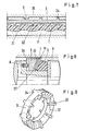
- FIG. 1 show the elements of an arrangement with an elastomer sealing ring 4 and a support ring 3.
- the sealing ring and the support ring are installed in a radial groove of the cylindrical outer part 8.
- the sealing ring forms, together with the surface of the shaft 5, the sliding sealing surface 45.
- the sealing ring first lies against the projections 32 of the support ring 3.
- the sections of the sealing ring lying between the projections bend axially.
- the sealing ring including the pressure-side edge 451 of the sliding sealing surface, assumes a wavy shape.
- the sealing ring lies on the surface of the support ring over the entire circumference, as a result of which its maximum deformation is limited and its shape can be defined at maximum deformation.
- projections 34 are attached, into which pins 6 engage to prevent rotation between the outer part and the support ring.
- the anti-rotation lock between the sealing ring and the support ring takes place automatically in that a positive connection is created as a result of the deformation-related interlocking of the sealing ring and the support ring.
- the pressure-side projections 32 are wave-shaped and the projections 34 are prismatic.
- 3 shows an arrangement in which the sealing ring 4 and the support ring 3 are arranged in a groove in the shaft, the sliding sealing surface 48 being formed by a peripheral surface of the cylindrical outer part 8.
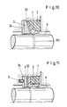
- Figures 4 to 6 show the elements of an arrangement with a sealing ring 1 made of plastic, an elastomer ring 2 as a clamping ring and secondary seal and a support ring 3.
- Fig. 4 shows the arrangement as a shaft seal in longitudinal section, the sealing ring, the clamping ring and the Support ring are installed in a radial groove of the cylindrical outer part 8.
- the sealing edge 11 of the sealing ring 1 forms, together with the surface of the shaft 5, the sliding sealing surface 15. Under the action of the pressure p to be sealed, the sealing ring initially rests on the projections 32 of the support ring 3.
- the clamping ring 2 also bears against the projections 32.
- the parts of the sealing ring and the tension ring lying between the projections 32 bend in the direction of the shaft axis of rotation.
- the sealing ring including the pressure-side edge 151 a wavy shape on its sliding sealing surface.
- projections 34 are attached, into which projections 6 engage in order to prevent rotation between the outer part and the support ring.
- the anti-rotation lock between the sealing ring and the support ring takes place automatically in that a positive connection is created as a result of the deformation-related interlocking of the sealing ring and the support ring.
- FIG. 5 shows a perspective view of a support ring according to the invention, in which, for example, the pressure-side projections 32 are prismatic with radially directed longitudinal edges.
- the opposite projections 34 are, for example, of the same design as the projections 32, so that here the support ring is mirror-symmetrical with respect to its central plane perpendicular to the shaft axis.
- the sealing ring 1 with its sealing edge 11 is tensioned by a 0-ring 2 and sealed secondary.
- FIG. 6 shows a detail from a representation of the sealing arrangement according to FIGS. 4 and 5, which is developed in the plane.
- the deformation-related anchoring of the bent sealing ring 1 on the edges 36 of the prism-shaped projections 32 can be clearly seen.
- the ring web 35 of the support ring 3 begins to bend between the projections 34 as soon as the bent sealing ring 1 is supported on the parts of the surface 31 lying between the projections 32 at a specific pressure p. With increasing pressure, the deformation of the sealing ring can therefore increase even more, but more slowly because of the increased resistance to deformation due to the support ring.
- Fig. 7 shows a detail of a plane view of the sealing arrangement according to the invention with the sealing ring 1 and the support ring 3.
- the sealing ring rests on the prismatic projections 32 of the support ring while it is supported on prismatic projections 34 on a wall from which Protruding protrusions 6 to prevent rotation.
- the projections 32 and 34 are each offset by half a division on the circumference, so that here the deflection of the sealing ring no longer increases when it touches the surface 31 of the support ring, but the deflection between the projections 32 increases Pressure increases less because the area 35 of the ring land between the projections 34 is flexible.
- Figures 8 and 9 show the elements of an arrangement of the shaft seal according to the invention with a sealing ring 1 in the form of a conical disc spring with the sealing edge 11, a clamping ring 2 as an O-ring made of elastomer and a support ring 3 with projections 32 protruding from its conical end face 31 On its end face facing away from the pressure, the support ring has projections 34 into which pins 6 engage.
- Fig. 9 shows the conical support ring of the arrangement of FIG. 8 in a perspective view.
- Figures 10 and 11 show further variants of the shaft seal according to the invention, each with the sealing rings 1, the clamping rings 2, the support rings 3 with the projections 32 and 34 and the pins 6 engaging in the gaps between the projections 34 to prevent rotation in cross-section each from a radially or approximately radially extending wing, the extension of which leads approximately to the sliding sealing surface 151 and which lies against the support ring and changes the shape of the sliding sealing surface due to its deformation, and from a wing directed more axially towards the pressure side, onto which the clamping ring 2 mainly acts.
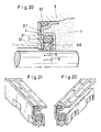
- FIG. 12 shows an optimal design of the shaft seal according to the invention with regard to friction and lubrication.
- the sealing ring 1 made of plastic has a sealing edge 11 which is as close as possible to its end face 17 facing away from the pressure p.
- the clamping ring 2 is an X-ring made of elastomer.
- the support ring 3 with its end projections 32 is connected to the housing 8 in a rotationally secured manner and arranged axially so that the end face 81 of the housing groove, on which the clamping ring rests on its pressure-facing end face, is offset axially by the dimension "T" relative to the pressure-facing end face 33 of the sealing ring is offset.
- the radial force transmitted from the clamping ring to the sealing ring can be determined to the size that is just necessary in terms of sealing technology, which on the other hand results in the smallest possible frictional force between the sealing ring and rotating shaft.
- the clamping ring ensures sufficient preload in the depressurized state.
- the pressurized state there is an extensive balance between the force exerted radially inward on the sealing ring by the force and the force acting radially outward from the medium pressure within the annular space 153 between the sealing ring and shaft.
- the annular space 153 between the sealing ring and shaft 5 is by means of at least one axial groove 154 connected in the sealing ring to the space to be sealed and thus always subjected to the pressure p, which relieves the sealing ring radially. Furthermore, at least one radial groove 155 is provided on the pressure-facing end face of the sealing ring in order to allow the pressure p to be sealed to also reach the groove space in front of the clamping ring. This ensures that the clamping ring is always loaded with the pressure p in full even when the pressure changes quickly.
- FIG. 13 shows a further embodiment of a shaft seal according to the invention in which, in addition to the generation of a ripple of the sliding sealing surface that increases as a function of pressure, the principle of the partial relief of the sealing edge 11 just explained from the effect of the pressure to be sealed is used. Both effects together result in an optimal sealing behavior with the lowest possible friction and thus practically no wear.
- FIG. 13 shows how a rotating shaft is sealed with a PTFE sealing edge ring 1, which is usually used as a hydraulic seal, with almost no leakage and with the least amount of friction, by the sealing ring being supported axially on the projections 32 of a support ring 3.
- the additional spacer ring 9 here causes a support of the rear side of the clamping ring which is offset axially by the dimension “T” and is designed here, for example, as an 0-ring. There is so much radial play between the sealing ring and the spacer ring that no radial force can be transmitted from the spacer ring to the sealing ring. As a result, as well as by the choice of the dimension "T", it is up to the seal designer to choose the pressure-dependent increasing radial pressure on the sealing edge 11 so that leakage on the one hand and frictional performance of the seal on the other are optimally coordinated with one another in accordance with the special task.
- the projections which, according to the invention, serve to axially support the sealing ring.
- the projections can be attached to a support ring or to the sealing ring.
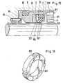
- Fig. 15 shows an arrangement with the sealing ring 1, the clamping ring 2, the support ring 3 with its shoulders 321 and 322. These parts are arranged in the sleeve 81, wherein on the side of the sealing ring facing the fluid to be sealed, the pump ring 83 with the Axis oblique grooves 831 and the return grooves 832 is arranged.
- the pump ring is secured by bending the edge 811 of the sleeve 81.
- the sleeve is sealed off from the housing 8 by the elastomer seal 82.
- the sleeve 81 has a plurality of elastic projections 84 distributed over the circumference and is supported axially on the housing via these, pins 85 which engage between the projections 84 , prevent relative rotation between the sleeve and the housing.
- 16 shows a perspective view of the pump ring 83 with its oblique grooves 831 and its axially arranged return grooves 832.
- FIG. 17 shows a sealing arrangement with the sealing ring 1, the tension ring 2, the support ring 3 and its shoulders 321, installed in the sleeve 81 and secured against slipping out on the high pressure side by the disk 86 and the snap ring 87.
- the sleeve 81 is supported in the housing 89 via the elastomer sealing ring 82 both axially and radially elastically.
- the seal 82 simultaneously seals the sleeve from the housing.
- a pin 85 engages radially in recesses 84 of the sleeve 81 and thus prevents relative rotation between the sleeve and the housing.
- FIG. 18 shows a perspective view of the support ring of the arrangement according to FIG. 17 with the projections 32 according to the invention and the heels 321 attached to both the projections and to the walls 31 of the support ring lying between the projections.
- These heels engage under corresponding edges 100 or protruding edges Surfaces of the sealing ring and thus prevent the sealing ring from sliding radially under the influence of the pressure difference or due to oblique bending during the deformation.
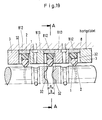
- FIG. 19 shows the arrangement of a rotary feedthrough with a total of 3 sealing systems of the type according to the invention.
- the system is constructed from individual ring-like bodies, all of which are connected to the housing 8 by brazing.
- the groove receiving the sealing ring 1 and the clamping ring 2 is formed by the support ring 3, the outer ring 812 and the ring 813.
- This rotary feedthrough system containing two separate fluid channels is mirror-symmetrical to the center plane A-A.
- the projections 32 of the two support rings 813 are offset in the circumferential direction by half a division of the projections 32 from one another.
- the spacing a of the projections in the central sealing groove is smaller than the axial width b of the seal 1, as a result of which a ripple in the circumference of the seal arises even when it is installed without pressure.
- FIGS. 20-22 finally show an embodiment of the shaft seal according to the invention with a sealing ring 1, a clamping ring 2, a support ring 3 and a sleeve 81.
- This sealing arrangement is preferably of the same construction as a radial shaft sealing ring, the elastomer seal 82 statically sealing the sleeve relative to the housing 8 .
- the sleeve and support ring are designed as drawn parts made of sheet metal and are integrally connected to one another, preferably by means of spot welding 311.
- the projections 32 on the support ring and the projections 815 on the inner end face of the sleeve are also stamped in during the manufacturing process of the sheet metal parts.
- the protrusions 32 and 815 are each one-half pitch in Arranged circumferentially offset from one another, such that the center of a projection 815 of the sleeve lies between two projections 32.
- the axial distance "a" between the projections 32 and 815 is smaller than the axial width "b" of the sealing ring, as a result of which a wavy shape seen in the circumferential direction is impressed on the sealing ring during installation.
Landscapes
- Engineering & Computer Science (AREA)
- General Engineering & Computer Science (AREA)
- Mechanical Engineering (AREA)
- Physics & Mathematics (AREA)
- Fluid Mechanics (AREA)
- Sealing Devices (AREA)
- Structures Of Non-Positive Displacement Pumps (AREA)
Description
Die Erfindung betrifft eine Wellendichtung mit einem elastischen, von dem abzudichtenden Druck beaufschlagten Dichtring, dessen niederdruckseitige Stirnfläche über mehrere Vorsprünge abgestützt ist, derart, daß seine mit einer zylindrischen Gegengleitfläche zusammenwirkende Dichtfläche einen wellenartigen Verlauf aufweist.The invention relates to a shaft seal with an elastic sealing ring acted upon by the pressure to be sealed, the low-pressure side end face of which is supported by a plurality of projections, in such a way that its sealing surface interacting with a cylindrical counter sliding surface has a wave-like course.
Die Funktionsfähigkeit von Wellendichtungen ist häufig infolge der an den Dichtflächen entstehenden Reibungswärme begrenzt. Insbesondere bei Dichtungen mit druckabhängiger Dichtflächenanpressung entsteht bei der Abdichtung unter hohem Druck eine verhältnismäßig große Reibungsverlustleistung. Bestehen die Dichtungen dazuhin noch aus Werkstoffen mit geringem Wärmeleitvermögen, so besteht die Gefahr, daß die für den Werkstoff zuträgliche Temperatur an den Dichtflächen überschritten wird und dadurch die Dichtung frühzeitig ausfällt.The functionality of shaft seals is often limited due to the frictional heat generated on the sealing surfaces. In the case of seals with pressure-dependent sealing surface pressure, a relatively high friction loss occurs when sealing under high pressure. If the seals also consist of materials with low thermal conductivity, there is a risk that the temperature at the sealing surfaces that is beneficial for the material will be exceeded and the seal will fail prematurely.
Eine in der Dichtungstechnik bekannte Maßnahme zur Verminderung der Reibleistung ist das gezielte Erzeugen eines die Gleitdichtflächen trennenden Schmierfilms, der den Dichtspalt ausfüllt. Die im Dichtspalt als Schmiermittel wirkende, abzudichtende Flüssigkeit kann die Reibungszahl beträchtlich vermindern. Gleichzeitig kann mittels einer dynamischen Schmierfilmbildung auch der Verschleiß der Gleitdichtflächen vermindert oder nahezu ganz vermieden werden.A measure known in sealing technology for reducing the friction is the targeted generation of a lubricating film that separates the sliding sealing surfaces and fills the sealing gap. The liquid to be sealed, which acts as a lubricant in the sealing gap, can considerably reduce the coefficient of friction. At the same time, the wear of the sliding sealing surfaces can be reduced or almost completely avoided by means of dynamic lubricating film formation.
Es ist bekannt, bei rotierenden Wellen einen Schmierfilm dadurch zu erzeugen, daß die Dichtkante in Umfangsrichtung betrachtet wellig ausgeführt ist. (GB-A-982 219, GB-A-933 133). Dies wird dadurch erreicht, daß der Dichtring axiale Vorsprünge aufweist, welche wechselnd auf beiden Stirnseiten entgegengesetzt gerichtet sind. Wird nun der mit den Vorsprüngen versehene Ring in eine Nut eingebaut, deren Breite geringer ist als die zwischen den Spitzen der Vorsprünge gemessene Breite des Dichtrings, so wird er mechanisch wellenartig verformt. Die in dieser Weise erreichte Wellenform ist daher durch die Gestalt des Rings mit der Nut von vornherein festgelegt, und zwar unbahängig von dem durch die Druckeinwirkung auf den Dichtring ausgeübten Axialschub. Die Abstimmung der Nutbreite auf die des Dichtrings schränkt die konstruktive Gestaltungsfreiheit wesentlich ein. Eine Verwendung dieses Dichtrings in herkömmlich vorgegebenen Einbauverhältnissen ist ausgeschlossen. Ein weiterer Nachteil der Dichtringe dieser Art ist, daß sie nicht drehsicher eingebaut sein. Auch verteuert die von einer einfachen Rotationsform abweichende Gestalt der Dichtringe deren Herstellung.It is known to produce a lubricating film in the case of rotating shafts in that the sealing edge is wavy when viewed in the circumferential direction. (GB-A-982 219, GB-A-933 133). This is achieved in that the sealing ring has axial projections which are alternately directed in opposite directions on both end faces. If the ring provided with the projections is now installed in a groove whose width is less than the width of the sealing ring measured between the tips of the projections, it is deformed mechanically in a wave-like manner. The waveform achieved in this way is therefore determined from the outset by the shape of the ring with the groove, specifically regardless of the axial thrust exerted by the pressure on the sealing ring. The coordination of the groove width to that of the sealing ring significantly limits the design freedom. The use of this sealing ring in conventional installation conditions is excluded. Another disadvantage of the sealing rings of this type is that they are not installed so that they cannot rotate. The shape of the sealing rings, which deviates from a simple rotational shape, also makes their manufacture more expensive.
Die der Erfindung zugrundeliegende Aufgabe besteht daher in der Schaffung einer Dichtung der eingangs genannten Art, die diese Nachteile wermeidet.The object underlying the invention is therefore to create a seal of the type mentioned, which avoids these disadvantages.
Die erfindungsgemäße Lösung besteht darin, daß die Vorsprünge an einem Stützring angeordnet sind und der Dichtringquerschnitt zu wellenartiger Verformung unter der Einwirkung des abzudichtenden Drucks bemessen ist.The solution according to the invention consists in that the projections are arranged on a support ring and the sealing ring cross section is dimensioned for wave-like deformation under the action of the pressure to be sealed.
Infolge der wellenartigen Verformung des gesamten Dichtringquerschnitts wird auch der von Teilen dieses Querschnitts gebildete hochdruckseitige Dichtflächenrand in erwünschter Weise wellenartig verformt, so daß die Voraussetzungen für die Bildung eines hydrodynamischen Schmierfilms verbessert werden. Außerdem wirken die Vorsprünge als Verdrehsicherung.As a result of the wave-like deformation of the entire sealing ring cross section, the high-pressure side sealing surface edge formed by parts of this cross section is also deformed in a desired manner, so that the conditions for the formation of a hydrodynamic lubricating film are improved. In addition, the projections act as an anti-twist device.
Bei der Verwendung von Elastomer-Dichtringen wird der Erfindungsgedanke vorzugsweise dadurch verwirklicht, daß niederdruckseitig ein Stützring angeordnet wird, der auf seiner dem Dichtring zugewandten Seitenfläche wellenförmige Vorsprünge aufweist. Dabei kann die Steilheit der Wellen in Umfangsrichtung gesehen an den ansteigenden und den abfallenden Wellenflanken ungleich ausgeführt werden. In denjenigen Umfangsbereichen in denen sich der Dichtring unter der zu erwartenden Druckdifferenz am Stützring anlegt und in denen daher der Verlauf seiner Dichtflächenbegrenzung von dem Verlauf der Wellen des Stützrings bestimmt ist, kann der Konstrukteur daher die Schleppwirkung und damit die Schmierfilmbildung gezielt im Hinblick auf den abzudichtenden Druck steuern. Insbesondere für die Abdichtung hoher Druckdifferenzen kann es vorteilhaft sein, die Schleppgeschwindigkeitskomponente vom abzudichtenden Raum in den Dichtspalt hinein kleiner zu wählen als die Komponente, die die im Spalt befindliche Flüssigkeit wieder in den Hochdruckraum zurückschleppt. Wegen der Asymmetrie des Pressungsverlaufs im Dichtspalt ergibt sich in diesem Fall die beste dynamische Dichtwirkung.When using elastomer sealing rings, the inventive idea is preferably realized in that a support ring is arranged on the low pressure side, which has wavy projections on its side surface facing the sealing ring. The steepness of the waves, seen in the circumferential direction, can be made unequal on the rising and falling wave flanks. In those circumferential areas in which the sealing ring contacts the support ring under the pressure difference to be expected and in which the course of its sealing surface limitation is determined by the course of the shafts of the support ring, the designer can therefore selectively influence the drag effect and thus the formation of the lubricating film with a view to the one to be sealed Control pressure. In particular for the sealing of high pressure differences, it can be advantageous to choose the towing speed component from the space to be sealed into the sealing gap to be smaller than the component that tows the liquid in the gap back into the high-pressure space. Because of the asymmetry of the pressure profile in the sealing gap, the best dynamic sealing effect results in this case.
Die Vorsprünge des Stützrings können erfindungsgemäß auch dergestalt ausgeführt werden, daß der Dichtring bei niederem Druck nur an den Kanten oder den Vorderflächen der Vorsprünge anliegt und erst bei ansteigendem Druck der Dichtring sich an weitere Teile der Stirnfläche des Stützrings anlegt. Diese Anordnung ist deshalb besonders vorteilhaft, weil sich hier die Welligkeit des Dichtflächenrands mit steigendem Druck kontinuierlich vergrößert und damit in erwünschter Weise die hydrodynamische Schmierwirkung mit steigendem Druck zunimmt.The projections of the support ring can also be designed according to the invention in such a way that the sealing ring only rests at low pressure on the edges or the front surfaces of the projections and only with increasing pressure does the sealing ring contact other parts of the end face of the support ring. This arrangement is particularly advantageous because the ripple of the sealing surface edge increases continuously with increasing pressure and thus the hydrodynamic lubricating effect increases in a desired manner with increasing pressure.
Des weiteren können die Vorsprünge mit Vorteil prismenähnlich kantig oder mit geringem Krümmungsradius ausgeführt werden, so daß der Dichtring mit hoher örtlicher Flächenpressung und verhältnismäßig starker örtlicher Verformung anliegt. Der Dichtring wird somit an den Kanten der prismenartigen Vorsprünge formschlüssig verankert, wodurch sich die erforderliche Verdrehsicherung zwischen Dichtring und Stützring ergibt, was insbesondere dann von Bedeutung ist, wenn der Dichtring ein Kunststoffring mit gegenüber einem Elastomerring großer Biegesteifigkeit ist.Furthermore, the projections can advantageously be prism-like edged or with a small radius of curvature, so that the sealing ring rests with high local surface pressure and relatively strong local deformation. The sealing ring is thus positively anchored to the edges of the prism-like projections, which results in the required anti-rotation protection between the sealing ring and the support ring, which is then particularly of It is important if the sealing ring is a plastic ring with great flexural rigidity compared to an elastomer ring.
Bei der Verwendung von verhältnismäßig biegesteifen Dichtringen aus Kunststoff werden zusätzlich in bekannter Weise Spannringe aus Elastomer verwendet, die den Dichtring zur Unterstützung der Dichtwirkung vorspannen und gleichzeitig als Nebenabdichtung wirksam sind. Bei solchen Anordnungen wird vorzugsweise der die Vorsprünge aufweisende Stützring so ausgeführt, daß der radial zum Dichtring versetzt angeordnete Spannring ebenfalls an den Vorsprüngen des Stützrings anliegt, das heißt, daß die Vorsprünge radial über die ganze Stirnfläche des Stützrings sich erstrecken und daher sowohl den Dichtring als auch den Spannring abstützen. Jedoch ist es auch möglich, daß sie lediglich den Dichtring abstützen.When using relatively rigid plastic sealing rings, clamping rings made of elastomer are additionally used in a known manner, which prestress the sealing ring to support the sealing effect and, at the same time, are effective as a secondary seal. In such arrangements, the support ring having the projections is preferably designed such that the clamping ring, which is arranged offset radially to the sealing ring, also bears on the projections of the support ring, that is to say that the projections extend radially over the entire end face of the support ring and therefore both the sealing ring and also support the clamping ring. However, it is also possible that they only support the sealing ring.
Werden erfindungsgemäß an beiden gegenüberliegenden Stirnflächen des Stützrings Vorsprünge angebracht, so ergeben sich dadurch weitere wesentliche Vorteile der Dichtungsanordnung. Wenn sich bei einer solchen Anordnung der Dichtring zwischen den Vorsprüngen so weit durchgebogen hat, daß er auch an dem zwischen den Vorsprüngen liegenden Teil des Ringstegs des Stützrings zur Anlage kommt, so kann bei weiterer Drucksteigerung einer Zunahme der Welligkeit nur bei entsprechender Verformung des auf der anderen Seite nur partiell abgestützten Stützrings erfolgen. Der Konstrukteur hat es damit in der Hand, durch geeignete Abstimmung der Biegesteifigkeit sowohl des Dichtrings als auch des Stützrings eine bis zum höchsten abzudichtenden Druck zunehmende Welligkeit des hochdruckseitigen Dichtflächenrandes druckabhängig in solcher Weise zu steuern, daß der Dichtring der Verformungszunahme bei hohem Druck einen vorherbestimmbar größeren Widerstand entgegensetzt als bei niederem Druck. Ein weiterer Vorteil der auf der Niederdruckseite des Stützrings zusätzlich angebrachten Vorsprünge besteht darin, daß sie als Anschläge zur Verdrehsicherung des Stützrings dienen können. Vorzugsweise in der Wand des Gehäuses oder in einer Stirnfläche der Welle, an die sich der Stützring unter Druckeinwirkung anlegt, werden Vorsprünge, Stifte oder dergleichen angebracht, die in die Lücken zwischen den Vorsprüngen auf der druckabgewandten Seite des Stützrings eingreifen. Schließlich wird durch das beidseitige Anbringen von gleichartigen Vorsprüngen am Stützring erfindungsgemäß als weiterer Vorteil die Möglichkeit eines versehentlich seitenverkehrten Einbaus des Stützrings ausgeschlossen.If projections are attached to both opposite end faces of the support ring according to the invention, this results in further essential advantages of the sealing arrangement. If with such an arrangement the sealing ring between the projections has bent so far that it also comes to rest on the part of the ring web of the support ring lying between the projections, then an increase in the ripple can only increase with a corresponding increase in pressure if the pressure on the other side only partially supported support ring. The designer has it in his hand, by suitably adjusting the bending stiffness of both the sealing ring and the support ring, to control the ripple of the high-pressure side sealing surface edge, which increases to the highest pressure to be sealed, in such a way that the sealing ring increases the deformation at a higher pressure under a predetermined pressure Resistance opposed to low pressure. Another advantage of the projections additionally provided on the low-pressure side of the support ring is that they can serve as stops for securing the support ring against rotation. Preferably, in the wall of the housing or in an end face of the shaft, to which the support ring is placed under pressure, protrusions, pins or the like are attached, which engage in the gaps between the projections on the side of the support ring facing away from the pressure. Finally, according to the invention, by attaching similar projections to the support ring on both sides, the possibility of an inadvertently reversed installation of the support ring is excluded as a further advantage.
Eine besonders vorteilhafte Dichtungsanordnung wird erfindungsgemäß dadurch erreicht, daß als Dichtring eine Ringscheibe in der Art einer Tellerfeder verwendet wird, die sich auf einer mit Vorsprüngen versehenen, konischen Stirnfläche des Stützrings abstützt. Vorzugsweise wird auch hier in bekannter Weise die Dichtwirkung gegenüber dem bewegten Maschinenteil dadurch erreicht, daß eine am Dichtring angebrachte Kante an die Gegengleitfläche angepreßt wird.A particularly advantageous sealing arrangement is achieved according to the invention in that an annular disk in the manner of a plate spring is used as the sealing ring, which is supported on a conical end face of the support ring provided with projections. Preferably, the sealing effect against the moving machine part is also achieved in a known manner in that an edge attached to the sealing ring is pressed against the counter sliding surface.
Beidseitig oder einseitig mit Vorsprüngen versehene Stützringe können erfindungsgemäß ohne weiteres auch in Verbindung mit an sich für Axialbewegung vorgesehene Hydraulik-Dichtkantenringen zur Abdichtung rotierender Wellen verwendet werden.Support rings provided on both sides or on one side with projections can, according to the invention, also be used without difficulty in connection with hydraulic sealing edge rings which are provided per se for axial movement for sealing rotating shafts.
Eine in wirtschaftlicher Hinsicht besonders vorteilhafte Bauweise der erfindungsgemäß mit Vorsprüngen versehenen Stützringe ergibt sich, wenn sie aus Endlosbändern hergestellt werden. Damit können auch hier Dichtungsanordungen für beliebige Wellendurchmesser mittels ein und desselben "Stützbandes" hergestellt werden, das vor der Montage auf die erforderliche Länge geschnitten und unter Belassen eines Stoßspalts ringförmig gebogen in die entsprechende Ringnut eingebaut wird.An economically particularly advantageous construction of the support rings provided with projections according to the invention results if they are produced from endless belts. This means that sealing arrangements for any shaft diameter can also be produced here by means of one and the same "support band", which is cut to the required length before installation and is built into the corresponding annular groove in an annular manner while leaving an impact gap.
Schließlich kann die erfindungsgemäß druckabhängig zunehmende Welligkeit des hochdruckseitigen Dichtflächenrands bei Dichtringen aus Kunststoff auch dadurch erreicht werden, daß die Vorsprünge an der druckabgewandten Stirnfläche des Dichtrings angebracht werden. Vorzugsweise kann der Dichtring in diesem Fall an einer ebenen Wand abgestützt werden, wobei jedoch wiederum die Vorsprünge die Nebenfunktion der Verdrehsicherung übernehmen können.Finally, the ripple of the sealing surface edge on the high-pressure side, which is pressure-dependent, according to the invention, can also be achieved in the case of sealing rings made of plastic, in that the projections are attached to the end face of the sealing ring facing away from the pressure. In this case, the sealing ring can preferably be supported on a flat wall, but again the projections can take on the secondary function of the anti-rotation device.
Eine in technischer Hinsicht optimale Bauweise einer Dichtungsanordnung mit den erfindungsgemäßen Merkmalen ergibt sich, wenn durch eine besondere geometrische Anordnung des Spannrings relativ zur Dichtkante des Dichtrings einersetis gerade die dichtungstechnisch erforderliche minimale Dichtkantenanpressung erzeugt wird und andererseits infolge eines partiell sich durchbiegenden Dichtringquerschnitts hochdruckseitig ein axial wellenförmiger Dichtflächenrand erzeugt wird. Dies wird erfindungsgemäß dadurch erreicht, daß die Ebene, in der der Dichtring an den Vorsprüngen zur Anlage kommt, axial gegenüber der druckabgewandten Anlagefläche des Spannrings zur Niederdruckseite hin versetzt angeordnet ist, und gleichzeitig in bekannter Weise /4/ die Dichtkante des Dichtrings in unmittelbarer Nähe der druckabgewandten Stirnfläche des Dichtrings angeordnet ist. Die Kombination der an sich bekannten Entlastung der Dichtkante vom abzudichtenden Druck einerseits mit der erfindungsgemäßen, druckabhängig zunehmenden Schmierwirkung infolge des sich wellenförmig verformenden hochdruckseitigen Dichtflächenrandes ergibt zusammen eine auf andere Weise nicht erreichbare Standzeit der Dichtung. Gleichzeitig wird bei dieser Dichtungsanordnung sowohl die beim Anfahren zu überwindende Haftreibung als auch die Gleitreibung beim andauernden Lauf der Welle minimal. Dadurch können einerseits unerwünschte Ruck-Gleitbewegungen (Stick-Slip) vermieden werden und andererseits bleibt die Reibungsverlustleistung im gesamten . Betriebsbereich der Dichtung klein.A technically optimal design of a sealing arrangement with the features according to the invention is obtained if a special geometrical arrangement of the clamping ring relative to the sealing edge of the sealing ring einersetis produces the minimum sealing edge pressure required in terms of sealing technology and, on the other hand, an axially wavy sealing surface edge on the high pressure side due to a partially bending sealing ring cross section is produced. This is achieved according to the invention in that the plane in which the sealing ring comes into contact with the projections is axially offset from the pressure-facing contact surface of the clamping ring towards the low-pressure side, and at the same time / 4 / the sealing edge of the sealing ring in the immediate vicinity the pressure-facing end face of the sealing ring is arranged. The combination of the known relief of the sealing edge from the pressure to be sealed, on the one hand, with the lubrication effect, which increases according to the pressure, as a result of the undulating deforming high-pressure side sealing surface edge, together results in a service life of the seal that cannot be achieved in any other way. At the same time with this sealing arrangement, both the static friction to be overcome when starting and the Minimal sliding friction when the shaft runs continuously. On the one hand, this allows undesired jerk-sliding movements (stick-slip) to be avoided and, on the other hand, the overall friction loss remains. Operating range of the seal is small.
In manchen Fällen ist es erforderlich, daß der Dichtring radialen Bewegungen der Wellenoberfläche, die von Unrundheit, Wellenschlag oder dergleichen herrühren können, folgen kann. Die unmittelbare Radialbeweglichkeit des Dichtrings in seiner Aufnahmenut kann aber durch die zwischen der Dichtung und den als Anlageflächen wirkenden, erfindungsgemäßen Vorsprüngen auftretende Reibung behindert sein. Dieser Nachteil wird erfindungsgemäß dadurch beseitigt, daß der Dichtring in einer Hülse angeordnet ist, wobei die Hülse gegenüber dem Gehäuse ein radiales Spiel aufweist. Das Spiel wird dabei mindestens so groß gewählt, daß die vom Dichtring auf die Hülse übertragene Radialbewegung der Welle ohne eine radiale Berührung zwischen der Hülse und dem Gehäuse erfolgen kann. Die Hülse wird gegenüber dem Gehäuse durch einen weiteren Dichtring abgedichtet und axial abgestützt.In some cases, it is necessary for the sealing ring to be able to follow radial movements of the shaft surface, which can result from out-of-roundness, shaft runout or the like. The immediate radial mobility of the sealing ring in its receiving groove can, however, be impeded by the friction occurring between the seal and the projections according to the invention acting as contact surfaces. This disadvantage is eliminated in accordance with the invention in that the sealing ring is arranged in a sleeve, the sleeve having radial play with respect to the housing. The game is chosen at least so large that the radial movement of the shaft transmitted from the sealing ring to the sleeve can take place without radial contact between the sleeve and the housing. The sleeve is sealed from the housing by a further sealing ring and axially supported.
Bei hohem abzudichtenden Druck kann der zwischen der Dichtfläche und dem Stützring liegende Teil des Dichtrings sich durch die radial gerichtete Presskraft des Spannrings in unerwünschter Weise radial so verformen, daß die Dichtfläche eine unerwünschte Vergrößerung erfährt. Dieser Nachteil wird erfindungsgemäß dadurch beseitigt, daß jeder Vorsprung einen Absatz aufweist, der dem Dichtring an derjenigen Seite, zu der hin er sich zu verformen trachtet, radial abstützt. Der Absatz kann ein Abschnitt einer Kegelfläche oder einer Zylinderfläche sein. Der Dichtring legt sich dann, wenn er durch den Spannring radial verformt wird, an den Absatz an, wodurch eine weitere Radialbewegung des Dichtrings verhindert wird. Damit die zwischen den Vorsprüngen liegenden, vom Druck axial verformten Bereiche des Dichtrings ebenfalls radial abgestützt werden, können auch an den zwischen den Vorsprüngen liegenden Flächen des Stützrings solche Absätze angeordnet sein. Obwohl erfindungsgemäß die Radialbeweglichkeit zwischen Dichtring und Stützring in erwünschter Weise durch die Absätze behindert ist, ermöglicht nach wie vor die globale Radialbeweglichkeit der den Dichtring aufnehmenden Hülse die Anpassung des Dichtrings an statische oder dynamische Exzentrizitäten des rotierenden Maschinenteils.At high pressure to be sealed, the part of the sealing ring lying between the sealing surface and the support ring can deform radially in an undesirable manner by the radially directed pressing force of the clamping ring in such a way that the sealing surface is undesirably enlarged. This disadvantage is eliminated in accordance with the invention in that each projection has a shoulder which radially supports the sealing ring on the side to which it is trying to deform. The shoulder can be a section of a conical surface or a cylindrical surface. When it is deformed radially by the clamping ring, the sealing ring rests against the shoulder, which prevents further radial movement of the sealing ring. So that the areas of the sealing ring lying between the projections and axially deformed by the pressure are also supported radially, such shoulders can also be arranged on the surfaces of the supporting ring lying between the projections. Although according to the invention the radial mobility between the sealing ring and the support ring is hindered by the shoulders, the global radial mobility of the sleeve receiving the sealing ring still enables the sealing ring to be adapted to static or dynamic eccentricities of the rotating machine part.
Entstehen infolge hoher Anpresskräfte des Dichtrings gegenüber dem rotierenden Maschinenteil und gleichzeitig hoher relativer Gleitgeschindigkeit auch große Reibleistungen, so besteht die Forderung, die Erwärmung des abzudichtenden Fluids in unmittelbarer Nähe der Dichtfläche durch besondere Maßnahmen zu begrenzen. Erfindungsgemäß wird dies dadurch erreicht, daß die an sich schon durch die Umfangswelligkeit der erfindungsgemäßen Dichtungsanordnung erzeugte Flüssigkeitsströmung durch einen zwangsläufigen Austausch der die gesamte Dichtung umgebende Flüssigkeitsmenge verstärkt wird. Eine zusätzliche Kühlung der wärmeerzeugenden Gleitdichtflächen wird in besonders vorteilhafter Weise dadurch erzeugt, daß seitlich vom Dichtring ein relativ zu diesem ruhender Pumpring angeordnet wird. Der Pumpring bildet gegenüber einer Umfangsfläche des rotierenden Maschinenteils einen engen Spalt, und weist an seiner diesen Spalt bildenden Oberfläche mehrere zur Wellenachse schräg angeordnete Nuten auf. Infolge der Rotationsbewegung wird die vom drehenden Maschinenteil mitgeschleppte Fluidmenge an den Seitenwänden der schrägen Nuten aufgestaut, wodurch eine axialgerichtete, kühlende Flüssigkeitsströmung erzeugt wird. Vorzugsweise wird dieser kühlende Fluidstrom durch mehrere in der gegenüberliegenden Umfangsfläche des Pumprings angeordnete Nuten zurückgeführt.If large frictional forces arise due to the high contact forces of the sealing ring compared to the rotating machine part and at the same time high relative sliding speed, there is a requirement to limit the heating of the fluid to be sealed in the immediate vicinity of the sealing surface by special measures. According to the invention, this is achieved in that the liquid flow which is already generated per se by the circumferential ripple of the sealing arrangement according to the invention is reinforced by an inevitable exchange of the amount of liquid surrounding the entire seal. Additional cooling of the heat-generating sliding sealing surfaces is produced in a particularly advantageous manner in that a pump ring which is at rest relative to this is arranged to the side of the sealing ring. The pump ring forms a narrow gap with respect to a peripheral surface of the rotating machine part, and has a plurality of grooves arranged obliquely to the shaft axis on its surface forming this gap. As a result of the rotational movement, the amount of fluid entrained by the rotating machine part is dammed up on the side walls of the oblique grooves, as a result of which an axially directed, cooling liquid flow is generated. This cooling fluid flow is preferably returned through a plurality of grooves arranged in the opposite circumferential surface of the pump ring.
Bei der Montage und beim Einbau der verschiedenen Teile des erfindungsgemäßen Dichtsystems in die abzudichtende Maschine besteht einerseits die Gefahr, daß funktionsbestimmende Teile, beispielsweise ein asymmetrisch geformter Stützring, unzweckmäßig in verkehrter Lage eingebaut werden. Weiterhin besteht auch die Gefahr, daß die empfindliche Dichtkante des Dichtrings beim Einbau verletzt wird. Erfindungsgemäß wird dieser Nachteil dadurch beseitigt, daß das gesamte Dichtsystem, bestehend aus Dichtring, Spannring, Stützring und gegebenenfalls einem Pumpring bereits im Herstellerwerk in eine Hülse eingebaut wird, wobei eine montagegünstige Baueinheit entsteht. Die Montage der Baueinheit durch den Anwender ist dann sehr einfach, da diese als Ganzes nur noch in eine Gehäusebohrung der abzudichtenden Maschine eingesteckt werden muß.When assembling and installing the various parts of the sealing system according to the invention in the machine to be sealed, there is on the one hand the risk that function-determining parts, for example an asymmetrically shaped support ring, are inappropriately installed in the wrong position. There is also the risk that the sensitive sealing edge of the sealing ring will be damaged during installation. According to the invention, this disadvantage is eliminated by the fact that the entire sealing system, consisting of sealing ring, clamping ring, support ring and, if appropriate, a pump ring is already installed in a sleeve in the manufacturer's plant, resulting in an assembly which is easy to assemble. The assembly of the assembly by the user is then very simple, since it as a whole only has to be inserted into a housing bore in the machine to be sealed.
Wenn bei einer Maschine von einem stationären Gehäuse Fluide über mehrere, getrennte Kanäle in das rotierende Maschinenteil zu übertragen sind, so werden sogenannte Mehrfach-Drehdurchführungen verwendet. Dabei besteht die Aufgabe, axial aneinandergrenzende Ringräume gegeneinander abzudichten. Da es hier wegen der mehrfachen Dichtungsanordnung und entsprechend großer Gesamtreibleistung entscheidend darauf ankommt, daß die Reibleistung der einzelnen Dichtung möglichst gering ist, ist die Anwendung des erfindungsgemäßen Dichtsystems hier besonders vorteilhaft. Dabei stellt sich die besondere Aufgabe, jede einzelne der die Dichtungen aufnehmenden Nuten an mindestens einer ihrer Seitenwände mit den erfindungsgemäßen Vorsprüngen zu versehen. Diese Aufgabe wird fertigungstechnisch in besonders vorteilhafter Weise dadurch gelöst, daß die Nuten durch verschiedene axial aneinandergrenzende Ringe gebildet werden, wobei jeweils die eine druckabgewandte Nutseitenwand bildenden Ringoberflächen die erfindungsgemäßen Vorsprünge aufweisen.If fluids are to be transferred from a stationary housing to the rotating machine part via a plurality of separate channels in a machine, so-called multiple rotary unions are used. The task here is to seal axially adjacent annular spaces against one another. Since the multiple sealing arrangement and a correspondingly high total frictional power make it crucial that the friction of the individual seal is as low as possible, the use of the sealing system according to the invention is particularly advantageous here. The special task here is to provide each of the grooves receiving the seals on at least one of their side walls with the projections according to the invention. This object is achieved in a particularly advantageous manner in terms of production technology in that the grooves are formed by different axially adjacent rings, each of which is one ring surfaces forming pressure-facing groove side wall have the projections according to the invention.
Dichtsysteme der erfinungsgemäßen Art werden jedoch auch eingesetzt, wenn zu unterschiedlichen Zeiten auch unterschiedlich hohe Druckdifferenzen abzudichten sind. Falls nun etwa gleich nach der ersten Installation der Dichtung eine sehr kleine Druckdifferenz abzudichten ist, so kann es vorkommen, daß die auf den Dichtring dabei einwirkende Kraft noch nicht ausreicht, um eine die Schmierung begünstigende und das Mitdrehen des Dichtrings verhindernde wellenförmige Verformung des Dichtrings zu bewirken. In diesem Fall werden erfindungsgemäß an beiden, an den Dichtring angrenzenden Seitenwänden des Gehäuses, bzw. des die Dichtung umgebenden Raumes, erfindungsgemäße Vorsprünge angebracht, dergestalt, daß die in Umfangsrichtung gesehen jeweils um eine halbe Teilung gegeneinander versetzten Vorsprünge der gegenüberliegenden Seitenwände dem Dichtring bereits im druckdifferenzlos eingebauten Zustand eine wellige Form aufprägen. Dies wird in Verbindung mit den am Umfang gegeneinander versetzten Mitten der Vorsprünge dadurch erreicht, daß die dem Dichtring zugewandten Vorderflächen der Vorsprünge einen axial gemessenen Abstand aufweisen, der kleiner ist als die axial gemessene Breite des Dichtrings.Sealing systems of the type according to the invention are also used, however, if different pressure differences have to be sealed at different times. If a very small pressure difference is to be sealed immediately after the first installation of the seal, it may happen that the force acting on the seal ring is not sufficient to cause a wave-shaped deformation of the seal ring which promotes lubrication and prevents the seal ring from rotating cause. In this case, according to the invention, projections according to the invention are attached to both the side walls of the housing adjacent to the sealing ring, or the space surrounding the seal, in such a way that the projections of the opposite side walls offset in the circumferential direction from the opposite side walls by half a division already in the sealing ring Imprint a wavy shape when installed without differential pressure. This is achieved in connection with the circumferentially offset centers of the projections in that the front surfaces of the projections facing the sealing ring have an axially measured distance which is smaller than the axially measured width of the sealing ring.
Nachfolgend wird die Erfindung anhand der in der Zeichnung dargestellten Ausführungsbeispiele erläutert. Es zeigen:
Figur 1 einen Längsschnitt durch eine Dichtungsanordnung,Figur 2 einen in dieser Dichtungsanordnung verwendbaren Stützring,Figur 3 und 4 Längsschnitte durch zwei weitere Ausführungsformen, der Dichtungsanordnung,Figur 5 die perspektivische Ansicht eines Stützrings und eines Dichtrings mit Spannring,Figur 6 einen Auschnitt aus einer in die Ebene abgewickelten Darstellung der Dichtungsanordnung nach Figur 4,- Figur 7 eine der Figur 6 gleichende Darstellung mit einem abgewandelten Stützring,
Figur 8 einen Längsschnitt durch eine weitere Ausführungsform der Dichtungsanordnung,Figur 9 einen dafür verwendbaren Stützring in perspektivischer Darstellung,- Figur 10 bis 13 Längsschnitte durch weitere Ausführungsformen der Dichtungsanordnung,
- Figur 14 eine Reihe von Formvarianten der Vorsprünge,
Figur 15 einen Längsschnitt durch eine weitere Ausführungsform einer Dichtungsanordnung,- Figur 16 in perspektivischer Darstellung den dafür verwendbaren Pumpring,
Figur 17 einen Längsschnitt durch eine weitere Ausführungsform einer Dichtungsanordnung,- Figur 18 den dafür verwendbaren Stützring in perspektivischer Ansicht,
- Figur 19 einen Längsschnitt durch eine Mehrfachdichtungsanordnung,
- Figur 20 einen Längsschnitt durch eine weitere Ausführungsform der Dichtungsanordnung und
- Figur 21 und 22 die Abwicklung des Dichtelements gemäß Figur 20 in perspektivischer Darstellung mit unterschiedlicher Blickrichtung.
- FIG. 1 shows a longitudinal section through a sealing arrangement,
- FIG. 2 shows a support ring that can be used in this sealing arrangement,
- 3 and 4 longitudinal sections through two further embodiments, the sealing arrangement,
- FIG. 5 shows the perspective view of a support ring and a sealing ring with a clamping ring,
- FIG. 6 shows a detail from a representation of the sealing arrangement according to FIG. 4, which is developed in the plane,
- FIG. 7 shows a representation similar to FIG. 6 with a modified support ring,
- FIG. 8 shows a longitudinal section through a further embodiment of the sealing arrangement,
- FIG. 9 is a perspective view of a support ring that can be used for this,
- 10 to 13 longitudinal sections through further embodiments of the sealing arrangement,
- FIG. 14 shows a number of shape variants of the projections,
- FIG. 15 shows a longitudinal section through a further embodiment of a sealing arrangement,
- FIG. 16 shows a perspective view of the pump ring that can be used for this purpose,
- FIG. 17 shows a longitudinal section through a further embodiment of a sealing arrangement,
- FIG. 18 shows the support ring that can be used for this in a perspective view,
- FIG. 19 shows a longitudinal section through a multiple seal arrangement,
- 20 shows a longitudinal section through a further embodiment of the sealing arrangement and
- 21 and 22 show the development of the sealing element according to FIG. 20 in a perspective view with different viewing directions.
Die Figuren 1 bis 3 zeigen die Elemente einer Anordnung mit einem Elastomer-Dichtring 4 und einem Stützring 3. Gemäß Fig. 1 sind der Dichtring und der Stützring in einer radialen Nut des zylindrischen Außenteils 8 eingebaut. Der Dichtring bildet zusammen mit der Oberfläche der Welle 5 die Gleitdichtfläche 45. Unter der Einwirkung des abzudichtenden Druckes p legt sich der Dichtring zunächst an den Vorsprüngen 32 des Stützrings 3 an. Bei zunehmendem Druck biegen sich die zwischen den Vorsprüngen liegenden Teilstücke des Dichtrings axial durch. Dadurch nimmt der Dichtring einschließlich des druckseitigen Randes 451 der Gleitdichtfläche eine wellige Form an. Bei einer durch den Biegewiderstand des Dichtrings vorbestimmbaren Druckschwelle liegt der Dichtring an der Oberfläche des Stützrings über den gesamten Umfang an, wodurch seine maximale Verformung begrenzt und seine Gestalt bei maximaler Verformung definiert werden kann. An der vom Dichtring abgewandten Stirnfläche 33 des Stützrings sind Vorsprünge 34 angebracht, in die zwecks Verdrehsicherung zwischen Außenteil und Stützring Stifte 6 eingreifen. Die Verdrehsicherung zwischen Dichtring und Stützring erfolgt automatisch dadurch, daß infolge des verformungsbedingten Ineinandergreifens von Dichtring und Stüzring eine formschlüssige Verbindung entsteht. Bei dem Stützring gemäß Fig. 2 sind beispielsweise die druckseitigen Vorsprünge 32 wellenförmig und die Vorsprünge 34 prismatisch ausgeführt. Fig. 3 zeigt eine Anordnung, bei der der Dichtring 4 und der Stützring 3 in einer Nut der Welle angeordnet sind, wobei die Gleitdichtfläche 48 durch eine Umfangsfläche des zylindrischen Außenteils 8 gebildet wird.Figures 1 to 3 show the elements of an arrangement with an
Die Figuren 4 bis 6 zeigen die Elemente einer Anordnung mit einem Dichtring 1 aus Kunststoff, einem Elastomer-Ring 2 als Spannring und Nebenabdichtung und einem Stützring 3. Fig. 4 zeigt die Anordnung als Wellendichtung im Längsschnitt, wobei der Dichtring, der Spannring und der Stützring in einer radialen Nut des zylindrischen Außenteils 8 eingebaut sind. Die Dichtkante 11 des Dichtrings 1 bildet zusammen mit der Oberfläche der Welle 5 die Gleitdichtfläche 15. Unter der Einwirkung des abzudichtenden Drucks p legt sich der Dichtring zunächst an den Vorsprüngen 32 des Stützrings 3 an.Figures 4 to 6 show the elements of an arrangement with a
Gleichzeitig legt sich auch der Spannring 2 an den Vorsprüngen 32 an. Bei zunehmendem Druck biegen sich die zwischen den Vorsprüngen 32 liegenden Teile des Dichtrings und des Spannrings in Richtung der Wellendrehachse durch. Dadurch nimmt der Dichtring einschließlich des druckseitigen Randes 151 seiner Gleitdichtfläche eine wellige Form an. An der vom Dichtring abgewandten Stirnfläche 33 des Stützrings sind Vorsprünge 34 angebracht, in die zwecks Verdrehsicherung zwischen Außenteil und Stützring Vorsprünge 6 eingreifen. Die Verdrehsicherung zwischen Dichtring und Stützring erfolgt automatisch dadurch, daß infolge des verformungsbedingten Ineinandergreifens von Dichtring und Stützring eine formschlüssige Verbindung entsteht. Fig. 5 zeigt in perspektiver Darstellung einen erfindungsgemäßen Stützring, bei dem beispielsweise die druckseitigen Vorsprünge 32 prismenförmig mit radial gerichteten Längskanten ausgeführt sind. Die gegenüberliegenden Vorsprünge 34 sind beispielsweise gleich ausgeführt wie die Vorsprünge 32, so daß hier der Stützring in bezug auf seine zur Wellenachse senkrechte Mittelebene spiegelsymmetrisch ausgeführt ist. Der Dichtring 1 mit seiner Dichtkante 11 wird durch einen 0-Ring 2 gespannt und sekundär abgedichtet. Analog zur der Darstellung in Fig. 3 kann selbstverständlich auch die Kombination aus Dichtring, Spannring und Stützring so angeordnet werden, daß alle drei Ringe gemeinsam in einer radialen Nut der Welle liegen, wobei die dann außen liegende Dichtkante des Dichtrings gegen eine Umfangsfläche des zylindrischen Außenteils 8 abdichtend zur Anlage kommt. Fig. 6 zeigt einen Ausschnitt aus einer in die Ebene abgewickelten Darstellung der Dichtungsanordnung nach den Bildern 4 und 5. Hier wird die verformungsbedingte Verankerung des durchgebogenen Dichtrings 1 an den Kanten 36 der prismenförmigen Vorsprünge 32 deutlich erkennbar. Auch wird in dieser Darstellung deutlich, daß sich auch der Ringsteg 35 des Stützrings 3 zwischen den Vorsprüngen 34 durchzubiegen beginnt, sobald sich bei einem bestimmten Druck p der durchgebogene Dichtring 1 an den zwischen den Vorsprüngen 32 liegenden Teilen der Oberfläche 31 abstützt. Bei weiter zunehmendem Druck kann daher die Verformung des Dichtrings noch weiter zunehmen, allerdings langsamer wegen des durch den Stützring vergrößerten Verformungswiderstands.At the same time, the
Fig. 7 zeigt einen Ausschnitt aus einer in die Ebene abgewickelten Darstellung der erfindungsgemäßen Dichtungsanordnung mit dem Dichtring 1 und dem Stützring 3. Der Dichtring liegt an den prismatischen Vorsprüngen 32 des Stützrings an während dieser sich auf prismatischen Vorsprüngen 34 an einer Wand abstützt, aus der zwecks Verdrehsicherung Vorsprünge 6 herausragen. In diesem Ausführungsbeispiel sind die Vorsprünge 32 und 34 jeweils am Umfang um eine halbe Teilung gegeneinander versetzt, so daß hier die Durchbiegung des Dichtrings nicht mehr weiter zunimmt, wenn er die Oberfläche 31 des Stützrings berührt, wogegen aber die Durchbiegung zwischen den Vorsprüngen 32 bei steigendem Druck weniger stark zunimmt, da der Bereich 35 des Ringstegs zwischen den Vorsprüngen 34 nachgiebig ist.Fig. 7 shows a detail of a plane view of the sealing arrangement according to the invention with the sealing
Die Figuren 8 und 9 zeigen die Elemente einer Anordnung der erfindungsgemäßen Wellendichtung mit einem Dichtring 1 in der Form einer konischen Tellerfeder mit der Dichtkante 11, einem Spannring 2 als O-Ring aus Elastomer sowie einem Stützring 3 mit aus seiner konischen Stirnfläche 31 hervorstehenden Vorsprüngen 32. An seiner druckabgewandten Stirnfläche weist der Stützring Vorsprünge 34 auf, in die Stifte 6 eingreifen. Fig. 9 zeigt den konischen Stützring der Anordnung nach Fig. 8 in perspektiver Darstellung.Figures 8 and 9 show the elements of an arrangement of the shaft seal according to the invention with a
Die Figuren 10 und 11 zeigen weitere Varianten der erfindungsgemäßen Wellendichtung, jeweils mit den Dichtringen 1, den Spannringen 2, den Stützringen 3 mit den Vorsprüngen 32 und 34 sowie den in die Lücken zwischen den Vorsprüngen 34 zwecks Verdrehsicherung eingreifenden Stiften 6. Dabei besteht der Dichtring im Querschnitt jeweils aus einem radial oder angenähert radial verlaufenden Flügel, dessen Verlängerung etwa zur Gleitdichtfläche 151 führt und die an dem Stützring anliegt und durch ihre Verformung die Gestalt der Gleitdichtfläche verändert, sowie aus einem mehr axial zur Druckseite gerichteten Flügel, auf den der Spannring 2 hauptsächlich einwirkt.Figures 10 and 11 show further variants of the shaft seal according to the invention, each with the sealing rings 1, the clamping rings 2, the support rings 3 with the
Die Fig. 12 zeigt schließlich eine im Hinblick auf Reibung und Schmierung optimale Gestaltung der erfindungsgemäßen Wellendichtung. Der Dichtring 1 aus Kunststoff weist eine möglichst nahe seiner vom Druck p abgewandten Stirnfläche 17 liegende Dichtkante 11 auf. Der Spannring 2 ist ein X-Ring aus Elastomer. Der Stützring 3 mit seinen stirnseitigen Vorsprüngen 32 ist mit dem Gehäuse 8 verdrehgesichert verbunden und axial so angeordnet, daß die Stirnfläche 81 der Gehäusenut, an der der Spannring an seiner druckabgewandten Stirnfläche anliegt gegenüber der druckabgewandten Stirnfläche 33 des Dichtrings um das Maß "T" axial versetzt ist. Durch geeignete Wahl von "T" kann die vom Spannring auf den Dichtring übertragene Radialkraft auf die dichtungstechnisch gerade noch notwendige Größe festgelegt werden, wodurch sich andererseits die kleinste mögliche Reibungskraft zwischen Dichtring und rotierender Welle ergibt. So sorgt der Spannring einerseits für eine hinreichende Vorspannung im drucklosen Zustand. Andererseits besteht im druckbeaufschlagten Zustand ein weitgehender Ausgleich zwischen der von dem Spannring radial nach innen auf den Dichtring ausgeübten Kraft und der von dem Mediumsdruck innerhalb des Ringraums 153 zwischen Dichtring und Welle herrührenden, radial nach außen wirkenden Kraft. Durch geeignete Bemessung des Maßes "T" läßt sich dieser Kräfteausgleich in beliebiger Weise variieren.Finally, FIG. 12 shows an optimal design of the shaft seal according to the invention with regard to friction and lubrication. The sealing
Der Ringraum 153 zwischen Dichtring und Welle 5 ist mittels mindestens einer axialen Nut 154 im Dichtring mit dem abzudichtenden Raum verbunden und somit immer mit dem Druck p, den Dichtring radial entlastend, beaufschlagt. Weiterhin ist an der druckzugewandten Stirnfläche des Dichtrings mindestens eine radiale Nut 155 vorhanden, um den abzudichtenden Druck p auch in den Nutraum vor dem Spannring gelangen zu lassen. Dadurch ist sichergestellt, daß der Spannring auch bei schneller Änderung des Druckes immer mit dem Druck p in voller Höhe belastet wird.The
Fig. 13 zeigt eine weitere Ausführung einer erfindungsgemäßen Wellendichtung bei der neben der Erzeugung einer sich druckabhängig vergrößernden Welligkeit der Gleitdichtfläche das so eben erläuterte Prinzip der Teilentlastung der Dichtkante 11 von der Wirkung des abzudichtenden Drucks angewendet ist. Beide Wirkungen zusammen ergeben ein optimales Dichtverhalten bei kleinstmöglicher Reibung und damit praktisch keinen Verschleiß. In Fig. 13 ist gezeigt, wie mit einem üblicherweise als Hydraulikdichtung verwendeten PTFE-Dichtkantenring 1 eine rotierende Welle nahezu ohne Leckage und bei kleinster Reibung abgedichtet wird, indem sich der Dichtring axial an den Vorsprüngen 32 eines Stützrings 3 abstützt. Der zusätzliche Distanzring 9 bewirkt hier eine um das Maß "T" axial versetzte Abstützung der Rückseite des Spannrings, der hier beispielsweise als 0-Ring ausgeführt ist. Zwischen Dichtring und Distanzring ist soviel Radialspiel vorhanden, daß keine Radialkraft vom Distanzring auf den Dichtring übertragen werden kann. Dadurch, sowie durch die Wahl des Maßes "T" hat es der Konstrukteur der Dichtung in der Hand, die druckabhängig zunehmende radiale Anpressung der Dichtkante 11 so zu wählen, daß Leckage einerseits und Reibungsleistung der Dichtung andererseits entsprechend der speziellen Aufgabenstellung optimal aufeinander abgestimmt werden.13 shows a further embodiment of a shaft seal according to the invention in which, in addition to the generation of a ripple of the sliding sealing surface that increases as a function of pressure, the principle of the partial relief of the sealing
Fig. 14 zeigt eine Reihe von Formvarianten der Vorsprünge, die erfindungsgemäß zu axialen Abstützung des Dichtrings dienen. Die Vorsprünge können an einem Stützring oder am Dichtring angebracht sein.14 shows a series of shape variants of the projections which, according to the invention, serve to axially support the sealing ring. The projections can be attached to a support ring or to the sealing ring.
Fig. 15 zeigt eine Anordnung mit dem Dichtring 1, dem Spannring 2, dem Stützring 3 mit seinen Absätzen 321 und 322. Diese Teile sind in der Hülse 81 angeordnet, wobei auf der dem abzudichtenden Fluid zugewandten Seite des Dichtrings der Pumpring 83 mit den zur Achse schrägen Nuten 831 und den Rückführnuten 832 angeordnet ist. Der Pumpring wird durch Umbiegen des Randes 811 der Hülse 81 gesichert. Die Abdichtung der Hülse gegenüber dem Gehäuse 8 erfolgt durch die Elastomerdichtung 82. Die Hülse 81 weist eine Mehrzahl von über den Umfang verteilten, elastischen Vorsprüngen 84 auf und stützt sich über diese axial am Gehäuse ab, wobei Stifte 85, die zwischen die Vorsprünge 84 eingreifen, eine relative Verdrehung zwischen der Hülse und dem Gehäuse verhindern.Fig. 15 shows an arrangement with the sealing
Fig. 16 zeigt in perspektiver Darstellung den Pumpring 83 mit seinen schrägen Nuten 831 und seinen axial angeordneten Rückführnuten 832.16 shows a perspective view of the
Fig. 17 zeigt eine Dichtungsanordnung mit dem Dichtring 1, dem Spannring 2, dem Stützring 3 und dessen Absätzen 321, eingebaut in die Hülse 81 und gegen Herausrutschen auf der Hochdruckseite durch die Scheibe 86 und den Sprengring 87 gesichert. Die Hülse 81 stützt sich im Gehäuse 89 über den Elastomerdichtring 82 sowohl axial als auch radial elastisch ab. Die Dichtung 82 übernimmt gleichzeitig die Abdichtung der Hülse gegenüber dem Gehäuse. Ein Stift 85 greift radial in Ausnehmungen 84 der Hülse 81 ein und verhindert damit eine relative Verdrehung zwischen der Hülse und dem Gehäuse.17 shows a sealing arrangement with the sealing
Fig. 18 zeigt in perspektiver Darstellung den Stützring der Anordnung nach Figur 17 mit den erfindungsgemäßen Vorsprüngen 32 und den sowohl an den Vorsprüngen als auch an den zwischen den Vorsprüngen liegenden Wänden 31 des Stützrings angebrachten Absätzen 321. Diese Absätze greifen unter formentsprechende Kanten 100 oder vorspringende Flächen des Dichtrings und verhindern so ein radiales Gleiten des Dichtrings unter der Einwirkung der Druckdifferenz bzw. aufgrund schiefer Biegung bei der Verformung.18 shows a perspective view of the support ring of the arrangement according to FIG. 17 with the
Fig. 19 zeigt die Anordnung einer Drehdurchführung mit insgesamt 3 Dichtsytemen der erfindungsgemäßen Art. Das System ist aus einzelnen ringartigen Körpern aufgebaut, die allesamt mit dem Gehäuse 8 durch Hartlötung verbunden sind. Die den Dichtring 1 und den Spannring 2 aufnehmende Nut wird durch den Stützring 3, den Außenring 812 und den Ring 813 gebildet. Dieses zwei getrennte Fluidkanäle enthaltende Drehdurchführungs-System ist spiegelsymmetrisch zur Mittelebene A-A ausgeführt. Dabei sind die Vorsprünge 32 der beiden Stützringe 813 in Umfangsrichtung um eine halbe Teilung der Vorsprünge 32 gegeneinander versetzt angeordnet. Gleichzeitig ist in der mittleren Dichtungsnut der Abstand a der Vorsprünge kleiner als die axiale Breite b der Dichtung 1, wodurch bereits im drucklos eingebauten Zustand eine Welligkeit des Dichtungsumfangs entsteht.19 shows the arrangement of a rotary feedthrough with a total of 3 sealing systems of the type according to the invention. The system is constructed from individual ring-like bodies, all of which are connected to the
Fig. 20 - 22 zeigen schließlich eine Ausführung der erfindungsgemäßen Wellendichtung mit einem Dichtring 1, einem Spannring 2, einem Stützring 3 und einer Hülse 81. Diese Dichtungsanordnung ist vorzugsweise einbaugleich mit Radialwellendichtringen ausgeführt, wobei die Elastomerdichtung 82 die Hülse statisch gegenüber dem Gehäuse 8 abdichtet. Hülse und Stützring sind als Ziehteile aus Metallblech ausgeführt und stoffschlüssig, vorzugsweise mittels Punktschweißung 311 miteinander verbunden. Die Vorsprünge 32 am Stützring und die Vorsprünge 815 an der inneren Stirnfläche der Hülse sind beim Herstellvorgang der Blechteile mit eingeprägt. Die Vorsprünge 32 und 815 sind jeweils um eine halbe Teilung in Umfangsrichtung gegeneinander versetzt angeordnet, dergestalt, daß jeweils die Mitte eines Vorsprungs 815 der Hülse zwischen zwei Vorsprüngen 32 liegt. Der axiale Abstand "a" zwischen den Vorsprüngen 32 und 815 ist kleiner, als die axiale Breite "b" des Dichtrings, wodurch dem Dichtring bereits beim Einbau eine in Umfangsrichtung gesehen wellige Form aufgeprägt wird.20-22 finally show an embodiment of the shaft seal according to the invention with a
Literatur:
- /1/ Brink, R.V., "The heat load of an oil seal", Paper C1, 6. International Conference on Fluid Sealing, 1973, München
- /2/ Leyer, A., "Maschinenkonstruktionslehre", Technica Nr. 10, 1966, S. 941 ff
- /3/ Martini, L.J., "Slanted O-Rings Extend Shaft Life", Machine Design, Feb. 8,1979
- /4/ "Wellendichtung"
DE 3 207 327 A1 vom 1.3.1982
- / 1 / Brink, RV, "The heat load of an oil seal", Paper C1, 6th International Conference on Fluid Sealing, 1973, Munich
- / 2 / Leyer, A., "Machine construction theory", Technica No. 10, 1966, p. 941 ff
- / 3 / Martini, LJ, "Slanted O-Rings Extend Shaft Life," Machine Design, Feb. 8.1979
- / 4 / "shaft seal"
DE 3 207 327 A1 from 1.3.1982
Claims (18)
Priority Applications (1)
| Application Number | Priority Date | Filing Date | Title |
|---|---|---|---|
| AT85108671T ATE38418T1 (en) | 1984-07-11 | 1985-07-11 | SHAFT SEAL. |
Applications Claiming Priority (4)
| Application Number | Priority Date | Filing Date | Title |
|---|---|---|---|
| DE3425431 | 1984-07-11 | ||
| DE3425431A DE3425431C1 (en) | 1984-07-11 | 1984-07-11 | Shaft seal |
| DE3502799 | 1985-01-29 | ||
| DE19853502799 DE3502799A1 (en) | 1984-07-11 | 1985-01-29 | SHAFT SEAL |
Publications (2)
| Publication Number | Publication Date |
|---|---|
| EP0170928A1 EP0170928A1 (en) | 1986-02-12 |
| EP0170928B1 true EP0170928B1 (en) | 1988-11-02 |
Family
ID=25822793
Family Applications (1)
| Application Number | Title | Priority Date | Filing Date |
|---|---|---|---|
| EP85108671A Expired EP0170928B1 (en) | 1984-07-11 | 1985-07-11 | Shaft seal |
Country Status (4)
| Country | Link |
|---|---|
| US (1) | US4729569A (en) |
| EP (1) | EP0170928B1 (en) |
| DE (2) | DE3502799A1 (en) |
| DK (1) | DK314685A (en) |
Cited By (1)
| Publication number | Priority date | Publication date | Assignee | Title |
|---|---|---|---|---|
| DE8907606U1 (en) * | 1989-06-21 | 1990-10-18 | Feodor Burgmann Dichtungswerke Gmbh & Co, 8190 Wolfratshausen | Ring seal for the ball body of a rotary ball valve mounted in the cylinder head of an internal combustion engine |
Families Citing this family (49)
| Publication number | Priority date | Publication date | Assignee | Title |
|---|---|---|---|---|
| DE3502799A1 (en) * | 1984-07-11 | 1986-07-31 | Martin Merkel GmbH & Co KG, 2102 Hamburg | SHAFT SEAL |
| DE3616689C1 (en) * | 1986-05-16 | 1987-11-19 | Mueller Heinz Konrad Prof Dr I | poetry |
| DE3642721A1 (en) * | 1986-12-13 | 1988-06-16 | Lechler Elring Dichtungswerke | Ring seal arrangement |
| DE3705448A1 (en) * | 1987-02-20 | 1988-09-01 | Blohm Voss Ag | Sealing system |
| DE3716862A1 (en) * | 1987-05-20 | 1988-12-15 | Blohm Voss Ag | Arrangement for sealing rotating shafts |
| DE4213996A1 (en) * | 1992-04-29 | 1993-11-04 | Goetze Ag | Shaft sealing ring with dust protector - has spring support ring fitting on end face of dust protection ring which is fixed in groove under axial pressure. |
| DE4337813C2 (en) * | 1993-11-05 | 1996-04-18 | Fichtel & Sachs Ag | Swing motor |
| US5941534A (en) * | 1994-10-12 | 1999-08-24 | Honda Giken Kogyo Kabushiki Kaisha | Hydraulic seal system |
| JP3860283B2 (en) * | 1996-06-26 | 2006-12-20 | Nok株式会社 | Sealing device |
| US6340160B1 (en) * | 1997-09-30 | 2002-01-22 | Gilbert W. Younger | System for sealing relatively movable elements |
| EP2163795B1 (en) * | 2000-05-02 | 2012-05-02 | Halliburton Energy Services, Inc. | Seal assembly for limiting the movement of a seal within a seal housing |
| CN1320295C (en) * | 2001-06-04 | 2007-06-06 | Nok株式会社 | Sealing device |
| EP1308654A1 (en) * | 2001-10-31 | 2003-05-07 | Kalsi Engineering, Inc. | Hydrodynamic packing assembly |
| DE10215311A1 (en) * | 2002-04-08 | 2003-11-06 | Hammelmann Paul Maschf | seal means |
| US20050046114A1 (en) * | 2003-08-27 | 2005-03-03 | Bohner Stephan Ernst | Rotary seal member, assembly and methods for a hydraulic rotary swivel |
| US6896110B2 (en) * | 2003-09-25 | 2005-05-24 | Tenneco Automotive Operating Company Inc. | Temperature compensated dual acting slip |
| DE202004007291U1 (en) * | 2004-05-07 | 2005-09-15 | Viega Gmbh & Co Kg | Press connector assembly |
| DE202004007290U1 (en) * | 2004-05-07 | 2005-09-15 | Viega Gmbh & Co Kg | sealing element |
| WO2006102349A2 (en) | 2005-03-22 | 2006-09-28 | Kalsi Engineering, Inc. | Low torque hydrodynamic lip geometry for bi-directional rotation seals |
| CA2601655C (en) * | 2005-03-28 | 2013-09-24 | Kalsi Engineering, Inc. | Composite, high temperature, dynamic seal and method of making same |
| US20070013143A1 (en) * | 2005-07-18 | 2007-01-18 | Kalsi Engineering, Inc. | Filled hydrodynamic seal with contact pressure control, anti-rotation means and filler retention means |
| JP4579110B2 (en) * | 2005-09-07 | 2010-11-10 | 三菱電線工業株式会社 | Rotating shaft seal |
| WO2007079497A2 (en) | 2006-01-04 | 2007-07-12 | Kalsi Engineering, Inc. | Stabilizing geometry for hydrodynamic rotary seals |
| US8550467B2 (en) * | 2006-03-22 | 2013-10-08 | Kalsi Engineering, Inc. | Rotary seal with improved film distribution |
| DE102007016896A1 (en) * | 2007-04-10 | 2008-10-16 | Jost-Werke Gmbh | Ball coupling with relatively movably received seal |
| US20090108538A1 (en) * | 2007-10-24 | 2009-04-30 | Freudenberg-Nok General Partnership | Two-Component Seal With Integral Locking Feature To Prevent Relative Rotation |
| DE102008012676A1 (en) * | 2008-03-05 | 2009-09-17 | Hunger Maschinen Gmbh | Rotary union |
| US9845879B2 (en) | 2009-11-30 | 2017-12-19 | Kalsi Engineering, Inc. | High pressure dynamic sealing arrangement |
| US9429238B2 (en) | 2009-11-30 | 2016-08-30 | Kalsi Engineering, Inc. | Dynamic backup ring assembly |
| US9109703B2 (en) | 2010-02-11 | 2015-08-18 | Kalsi Engineering, Inc. | Hydrodynamic backup ring |
| DE102010001345B4 (en) * | 2010-01-28 | 2013-09-19 | Trelleborg Sealing Solutions Germany Gmbh | Rotary union |
| JP5598222B2 (en) * | 2010-09-30 | 2014-10-01 | 株式会社アドヴィックス | Shaft seal device and pump device and brake fluid pressure control device using the same |
| US20120223485A1 (en) * | 2011-03-04 | 2012-09-06 | Jeong-Jung Heo | Link seal for track of tracked vehicles |
| ITMI20111739A1 (en) * | 2011-09-27 | 2013-03-28 | Freni Brembo Spa | PISTON STOPPER DEVICE |
| US20140037488A1 (en) * | 2012-07-31 | 2014-02-06 | John Stewart Glen | Vane-type Compressors and Expanders with Minimal Internal Energy Losses |
| DE102013217581A1 (en) * | 2013-09-04 | 2015-03-05 | MTU Aero Engines AG | Sealing arrangement in an axial flow machine |
| US9617822B2 (en) | 2013-12-03 | 2017-04-11 | Baker Hughes Incorporated | Compliant seal for irregular casing |
| DE102014216268A1 (en) * | 2014-08-15 | 2016-02-18 | Trelleborg Sealing Solutions Germany Gmbh | Sealing arrangement with attenuator |
| US10344862B2 (en) * | 2015-01-12 | 2019-07-09 | Rolls-Royce Corporation | Shaft coupling seal assembly |
| DE102017207091A1 (en) * | 2016-06-30 | 2018-01-04 | Robert Bosch Gmbh | Valve for metering a fluid, fitting for a valve and fuel injection system |
| DE102016218239A1 (en) * | 2016-09-22 | 2018-03-22 | MTU Aero Engines AG | Sealing arrangement for a turbine intermediate housing of a gas turbine |
| US10330203B2 (en) | 2017-01-06 | 2019-06-25 | Kalsi Engineering Inc. | High pressure dynamic sealing device |
| DE102017204374A1 (en) * | 2017-03-16 | 2018-09-20 | Trelleborg Sealing Solutions Germany Gmbh | sealing arrangement |
| US10302200B2 (en) | 2017-05-16 | 2019-05-28 | Kalsi Engineering, Inc. | Seal for bi-directional rotation and pressure |
| AT16131U1 (en) * | 2017-06-09 | 2019-02-15 | Engel Austria Gmbh | Device for sealing a shaft for a molding machine |
| US11668399B2 (en) | 2018-05-15 | 2023-06-06 | Kalsi Engineering, Inc. | Rotary seal and method of making same |
| CA3120943C (en) | 2018-11-26 | 2023-01-03 | Kalsi Engineering, Inc. | Seal assembly with anti-rotation and stability features |
| US11125336B2 (en) * | 2019-06-17 | 2021-09-21 | Freudenberg-Nok General Partnership | Self energized seal |
| US20230349465A1 (en) * | 2022-05-02 | 2023-11-02 | Ariel Corporation | Laterally moveable compressor piston rod lip seal assembly |
Family Cites Families (16)
| Publication number | Priority date | Publication date | Assignee | Title |
|---|---|---|---|---|
| US1307901A (en) * | 1919-06-24 | fariand and l f | ||
| CH27569A (en) * | 1902-12-19 | 1904-01-31 | Sulzer Ag | Device for sealing cylindrical rotating bodies forming the closure of a pressure space |
| US1770509A (en) * | 1927-02-23 | 1930-07-15 | Wallace C Chambers | Flexible metallic packing |
| FR652389A (en) * | 1928-04-07 | 1929-03-07 | Shutter for axle boxes and shaft bearings rotating in both directions | |
| GB559736A (en) * | 1942-11-02 | 1944-03-02 | Pyrene Co Ltd | Improvements in gland packings |
| DE903878C (en) * | 1951-12-25 | 1954-02-11 | Iaweseria Ag | Stuffing box seal |
| GB762958A (en) * | 1953-09-25 | 1956-12-05 | Bristol Aeroplane Co Ltd | Improvements in or relating to sealing means for preventing or reducing the escape of a liquid through a gap between a pair of relatively rotating elements |
| FR82269E (en) * | 1962-06-06 | 1964-01-17 | Joint Francais | O-ring seal |
| FR1267218A (en) * | 1960-06-07 | 1961-07-21 | Joint Francais | O-ring seal |
| DE2206461C2 (en) * | 1972-02-11 | 1983-11-17 | Fa. Carl Freudenberg, 6940 Weinheim | Radial lip seal |
| US4336945A (en) * | 1977-03-18 | 1982-06-29 | Cr Industries | Sinuous seal with auxiliary excluder lips |
| US4175475A (en) * | 1977-11-30 | 1979-11-27 | General Motors Corporation | Worm thread seal for steering gear |
| US4323287A (en) * | 1979-10-03 | 1982-04-06 | The Torrington Company | Bearing seal |
| DE3207327A1 (en) * | 1982-03-01 | 1983-09-08 | Heinz Konrad Prof. Dr.-Ing. 7050 Waiblingen Müller | Shaft seal |
| AU566210B2 (en) * | 1983-05-19 | 1987-10-15 | Bw/Ip International, Inc. | Mechanical seal |
| DE3502799A1 (en) * | 1984-07-11 | 1986-07-31 | Martin Merkel GmbH & Co KG, 2102 Hamburg | SHAFT SEAL |
-
1985
- 1985-01-29 DE DE19853502799 patent/DE3502799A1/en not_active Withdrawn
- 1985-07-10 DK DK314685A patent/DK314685A/en not_active Application Discontinuation
- 1985-07-11 DE DE8585108671T patent/DE3566027D1/en not_active Expired
- 1985-07-11 EP EP85108671A patent/EP0170928B1/en not_active Expired
- 1985-07-11 US US06/754,516 patent/US4729569A/en not_active Expired - Fee Related
Cited By (1)
| Publication number | Priority date | Publication date | Assignee | Title |
|---|---|---|---|---|
| DE8907606U1 (en) * | 1989-06-21 | 1990-10-18 | Feodor Burgmann Dichtungswerke Gmbh & Co, 8190 Wolfratshausen | Ring seal for the ball body of a rotary ball valve mounted in the cylinder head of an internal combustion engine |
Also Published As
| Publication number | Publication date |
|---|---|
| DK314685A (en) | 1986-01-12 |
| DE3502799A1 (en) | 1986-07-31 |
| US4729569A (en) | 1988-03-08 |
| DK314685D0 (en) | 1985-07-10 |
| DE3566027D1 (en) | 1988-12-08 |
| EP0170928A1 (en) | 1986-02-12 |
Similar Documents
| Publication | Publication Date | Title |
|---|---|---|
| EP0170928B1 (en) | Shaft seal | |
| DE2939945C2 (en) | ||
| DE60207663T2 (en) | Brush seal and brush seal arrangement | |
| EP0980998B1 (en) | Radial shaft seal | |
| DE3320063C2 (en) | ||
| EP0139965B1 (en) | Seal ring for piston rods | |
| DE69016253T2 (en) | Non-rotating contactless mechanical seal. | |
| WO1987006991A1 (en) | Seal arrangement | |
| DE20121487U1 (en) | Shaft seal | |
| DE2756403C3 (en) | poetry | |
| DE2949839C2 (en) | Sealing ring | |
| DE10148388A1 (en) | Roller bearing for a clutch disengagement unit, comprises a rotating ring, a fixed ring, an inner chamber and ball bearings | |
| DE3213809C2 (en) | Cassette seal | |
| DE19509771C1 (en) | Sealing ring | |
| EP0130237A1 (en) | Ring seal for a shaft | |
| DE3217118C1 (en) | Seal arrangement for shafts | |
| DE2305826A1 (en) | SEAL RING ARRANGEMENT | |
| EP0798498B1 (en) | Radial lip seal with excluding effect independent of the rotation direction | |
| DE3425431C1 (en) | Shaft seal | |
| DE3434421A1 (en) | AUTOMATICALLY RESETTABLE BRAKE SHOE FOR PARTIAL COVER DISC BRAKES | |
| DE4222852A1 (en) | Roll bearing device - with connection ring between inner rings producing good seal to avoid leakage of oil or grease from bearing | |
| DE3323948C2 (en) | ||
| WO2019206360A1 (en) | Thrust washer for axial mounting of planets in a planetary transmission | |
| DE3208396C1 (en) | Piston ring | |
| DE60302547T2 (en) | GUIDE CONFIGURATION FOR PRESSURE BEARING ARRANGEMENT |
Legal Events
| Date | Code | Title | Description |
|---|---|---|---|
| PUAI | Public reference made under article 153(3) epc to a published international application that has entered the european phase |
Free format text: ORIGINAL CODE: 0009012 |
|
| AK | Designated contracting states |
Designated state(s): AT CH DE FR GB IT LI SE |
|
| 16A | New documents despatched to applicant after publication of the search report | ||
| 17P | Request for examination filed |
Effective date: 19860502 |
|
| 17Q | First examination report despatched |
Effective date: 19870721 |
|
| GRAA | (expected) grant |
Free format text: ORIGINAL CODE: 0009210 |
|
| AK | Designated contracting states |
Kind code of ref document: B1 Designated state(s): AT CH DE FR GB IT LI SE |
|
| REF | Corresponds to: |
Ref document number: 38418 Country of ref document: AT Date of ref document: 19881115 Kind code of ref document: T |
|
| REF | Corresponds to: |
Ref document number: 3566027 Country of ref document: DE Date of ref document: 19881208 |
|
| ITF | It: translation for a ep patent filed | ||
| GBT | Gb: translation of ep patent filed (gb section 77(6)(a)/1977) | ||
| ET | Fr: translation filed | ||
| PLBE | No opposition filed within time limit |
Free format text: ORIGINAL CODE: 0009261 |
|
| STAA | Information on the status of an ep patent application or granted ep patent |
Free format text: STATUS: NO OPPOSITION FILED WITHIN TIME LIMIT |
|
| 26N | No opposition filed | ||
| ITTA | It: last paid annual fee | ||
| EAL | Se: european patent in force in sweden |
Ref document number: 85108671.0 |
|
| REG | Reference to a national code |
Ref country code: FR Ref legal event code: TP |
|
| REG | Reference to a national code |
Ref country code: GB Ref legal event code: 732E |
|
| REG | Reference to a national code |
Ref country code: FR Ref legal event code: TP Ref country code: FR Ref legal event code: CD Ref country code: FR Ref legal event code: CA |
|
| REG | Reference to a national code |
Ref country code: GB Ref legal event code: 732E |
|
| REG | Reference to a national code |
Ref country code: GB Ref legal event code: IF02 |
|
| PGFP | Annual fee paid to national office [announced via postgrant information from national office to epo] |
Ref country code: GB Payment date: 20030625 Year of fee payment: 19 |
|
| PGFP | Annual fee paid to national office [announced via postgrant information from national office to epo] |
Ref country code: DE Payment date: 20030711 Year of fee payment: 19 |
|
| PGFP | Annual fee paid to national office [announced via postgrant information from national office to epo] |
Ref country code: SE Payment date: 20030716 Year of fee payment: 19 |
|
| PGFP | Annual fee paid to national office [announced via postgrant information from national office to epo] |
Ref country code: FR Payment date: 20030723 Year of fee payment: 19 |
|
| PGFP | Annual fee paid to national office [announced via postgrant information from national office to epo] |
Ref country code: AT Payment date: 20030729 Year of fee payment: 19 |
|
| PGFP | Annual fee paid to national office [announced via postgrant information from national office to epo] |
Ref country code: CH Payment date: 20030731 Year of fee payment: 19 |
|
| PG25 | Lapsed in a contracting state [announced via postgrant information from national office to epo] |
Ref country code: GB Free format text: LAPSE BECAUSE OF NON-PAYMENT OF DUE FEES Effective date: 20040711 Ref country code: AT Free format text: LAPSE BECAUSE OF NON-PAYMENT OF DUE FEES Effective date: 20040711 |
|
| PG25 | Lapsed in a contracting state [announced via postgrant information from national office to epo] |
Ref country code: SE Free format text: LAPSE BECAUSE OF NON-PAYMENT OF DUE FEES Effective date: 20040712 |
|
| PG25 | Lapsed in a contracting state [announced via postgrant information from national office to epo] |
Ref country code: LI Free format text: LAPSE BECAUSE OF NON-PAYMENT OF DUE FEES Effective date: 20040731 Ref country code: CH Free format text: LAPSE BECAUSE OF NON-PAYMENT OF DUE FEES Effective date: 20040731 |
|
| PG25 | Lapsed in a contracting state [announced via postgrant information from national office to epo] |
Ref country code: DE Free format text: LAPSE BECAUSE OF NON-PAYMENT OF DUE FEES Effective date: 20050201 |
|
| EUG | Se: european patent has lapsed | ||
| GBPC | Gb: european patent ceased through non-payment of renewal fee |
Effective date: 20040711 |
|
| REG | Reference to a national code |
Ref country code: CH Ref legal event code: PL |
|
| PG25 | Lapsed in a contracting state [announced via postgrant information from national office to epo] |
Ref country code: FR Free format text: LAPSE BECAUSE OF NON-PAYMENT OF DUE FEES Effective date: 20050331 |
|
| REG | Reference to a national code |
Ref country code: FR Ref legal event code: ST |