EP0169540B1 - Procédé et dispositif d'enregistrement et de reproduction d'un signal numérique avec une tête fixe - Google Patents
Procédé et dispositif d'enregistrement et de reproduction d'un signal numérique avec une tête fixe Download PDFInfo
- Publication number
- EP0169540B1 EP0169540B1 EP85109200A EP85109200A EP0169540B1 EP 0169540 B1 EP0169540 B1 EP 0169540B1 EP 85109200 A EP85109200 A EP 85109200A EP 85109200 A EP85109200 A EP 85109200A EP 0169540 B1 EP0169540 B1 EP 0169540B1
- Authority
- EP
- European Patent Office
- Prior art keywords
- data
- words
- tracks
- parity
- tape
- Prior art date
- Legal status (The legal status is an assumption and is not a legal conclusion. Google has not performed a legal analysis and makes no representation as to the accuracy of the status listed.)
- Expired - Lifetime
Links
Images


Classifications
-
- G—PHYSICS
- G11—INFORMATION STORAGE
- G11B—INFORMATION STORAGE BASED ON RELATIVE MOVEMENT BETWEEN RECORD CARRIER AND TRANSDUCER
- G11B5/00—Recording by magnetisation or demagnetisation of a record carrier; Reproducing by magnetic means; Record carriers therefor
- G11B5/02—Recording, reproducing, or erasing methods; Read, write or erase circuits therefor
- G11B5/09—Digital recording
-
- G—PHYSICS
- G11—INFORMATION STORAGE
- G11B—INFORMATION STORAGE BASED ON RELATIVE MOVEMENT BETWEEN RECORD CARRIER AND TRANSDUCER
- G11B20/00—Signal processing not specific to the method of recording or reproducing; Circuits therefor
- G11B20/10—Digital recording or reproducing
- G11B20/18—Error detection or correction; Testing, e.g. of drop-outs
- G11B20/1806—Pulse code modulation systems for audio signals
- G11B20/1809—Pulse code modulation systems for audio signals by interleaving
-
- G—PHYSICS
- G11—INFORMATION STORAGE
- G11B—INFORMATION STORAGE BASED ON RELATIVE MOVEMENT BETWEEN RECORD CARRIER AND TRANSDUCER
- G11B20/00—Signal processing not specific to the method of recording or reproducing; Circuits therefor
- G11B20/10—Digital recording or reproducing
- G11B20/12—Formatting, e.g. arrangement of data block or words on the record carriers
Definitions
- the present invention relates to recording and reproducing techniques on a digital audio tape by a stationary head, and more particularly to method and apparatus suitable for correcting and concealing a data error such as a dropout in a record medium.
- S-DAT Stationary-head Digital tape recording/reproducing apparatus Audio Tape- recorder
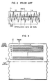
- Fig. 7 shows a format of odd/ even sample data interleaved by a skew pattern with respect to a tape transport direction.
- This error correction technique for correcting the random and burst errors is not sufficient to present and correct the data dropout in recording and reproducing the two-channel audio signal on the tape.
- the UK Patent Application GB 2 107 558 A discloses a multi-track digital recording and reproducing system with stationary magnetic heads.
- the data words are sufficiently spaced apart on the record tracks to make it highly unlikely that more than one word will be affected by a dropout effect, and the redundant parity words are recorded to an edge of the tape.
- the European Patent Application EP 0 146 639 shows a stationary head type PCM recorder whereby parity words are added to the input data words and whereby sets of consecutive ones of data words and added parity words are delayed before recording with one head per track.
- odd data and even data of two sampled channels that is, sample data adjacent to each other are separated from each other longitudinally of the tape, and an error detecting and correcting parity data generated from the odd and even data is inserted between those channels, and the parity data is arranged in a track on a tape edge.
- each track on a tape includes an L-channel data and an R-channel data. Accordingly, if a burst error occurs within the track, error data are distributed to both channels.
- the parity data is arranged in the track on the edge of the tape where errors frequently occur and the audio data is arranged in inner tracks where the occurrence of errors is relatively low.
- the data at the odd sample points and the data at the even sample points of the audio data are separated and the parity data is inserted therebetween so that the error concealment capability to the burst error is enhanced.
- a delay of the parity data is set to be larger than a delay of the audio data to prevent the reduction of the burst error correction capability due to the concentrated arrangement of the parity data.
- S-DAT European Patent Application No. 82108375.5 filed on September 10, 1982.
- a PCM data is recorded on a plurality of tracks, e.g. 20 tracks.
- Left and right time-serial audio signals L in and R in from the two-channel audio signal source are alternately selected by a channel selection circuit MPX, and they are time-division multiplexed as left and right sample signals in the order of L o , R o , L 1 , R 1 , L 2 , R 2 , ..., which are then transmitted as a serial signal.
- the analog signal from the channel selection circuit MPX is converted to a digital signal by an A/D converter, and the digital signal is sent to a digital signal processing circuit, where the time-serially transmitted data is stored in a RAM and the data is read from the memory in a different sequence.
- the interleaving is a data distribution processing to allow error correction of the data even if a dropout or burst error occurs in the recorded data. This process is carried out by an interleaver shown in Fig. 1 which is a data delaying and rearranging circuit.
- the interleaved signals on the input data L 1 , R i -L i+15 and R i-15 are arranged to construct an error detection and correction block, and by encoding using error detection and correction code such as Read-Solomon code parity words, for example, Q o , 0 1 , ..., and Q 7 or P o and P 1 are produced.
- error detection and correction code such as Read-Solomon code parity words, for example, Q o , 0 1 , ..., and Q 7 or P o and P 1 are produced.
- the signals processed in this manner are recorded on the magnetic tape by a multi-head (20-track head, for example) through recording amplifiers.
- the signals read from the magnetic tape by the multi-head are amplified and reshaped by reproducing pre-amplifiers, outputs of which are sent to a reproducing digital signal processing circuit, in which the input data are arranged to construct the error detection and correction block.
- the data having the sequence thereof changed by the interleaving is rearranged in the original sequence by a deinterleaver. This is called deinterleave processing.
- the deinterleaved digital signal is converted to an analog signal by a D/A converter, and the analog signal is divided into left and right channels by a demultiplexor to reproduce the two-channel audio signals L out and R out .
- Fig. 1 shows an interleave circuit for interleaving the data in the record mode.
- Numeral 1 denotes an uninter- leaved data
- numeral 2 denotes an interleaved data
- numeral 3 denotes a track number on a tape on which the interleaved data is recorded
- numerals 4-8 denote data delay circuits
- numerals 9a and 9b denote a C 2 -parity encoder and a C i -parity encoder which use a doubly- encoded error correction code.
- An example for constructing such encoders is disclosed in Odaka et al U.S. Patent 4,413,340.
- a PCM data to be recorded on the tape is distributed to 20 tracks. Accordingly, the interleaving process must take the data delay in the tape transport direction and the distribution of the data among the tracks into consideration.
- the dafa is delayed by the delay circuits 4-8 and then the data is distributed to the tracks as shown by numeral 3.
- the A/D converted L-R two-channel PCM signal 1 is delayed by the delay circuit 4 only for the odd data, and the error correction code generator 9a which may use the Read-Solomon code carries out the C 2 -encoding by the Read-Solomon code for the 32-word data (40, 32, 9) and adds parities Q oi , Q ij , ..., Q 71 .
- a delay d, by the delay circuit 4 may change from data to data. In this manner, the C 2 -parity encoder is constructed.
- the data delayed in the delay circuit 4 and the parities generated by the error correction code generator 9a are further delayed, that is, interleaved for each word by the delay circuits 5-8.
- the Read-Solomon code encoding (C i -encoding) is carried out for the 27 words of control signal words and data words of one block or C 2 parity words by the C,-encoder 9b (29, 27, 3) to produce C, parity words P o,j,k and P i,j,k ; and it is recorded in the tracks shown by 3.
- Fig. 3 shows a record track pattern on the tape.
- Numeral 10 denotes a magnetic tape
- numeral 11 denotes a center of the tape
- numeral 12 denotes a record track.
- the record track comprises 22 tracks, that is, 20 tracks for recording 20 PCM signals, an AUX track for recording an auxiliary signal other than the PCM signal, and a CUE track for recording fast access control signal.
- a track width may be 65 ⁇ and a track pitch may be 80 ⁇ m.
- the 22 tracks are arranged in one half widthwise area of the tape. The remaining half area is used to record signals when the tape is transported in the opposite direction. In this manner, reciprocal recording and reproducing is attained. In the following description, only the 20 tracks for recording the PCM signals are explained.
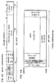
- Figs. 4A, 4B and 4C show a frame format of the track on which the PCM signal is recorded, a data record format in a field, and a block configuration.
- Numeral 13 denotes a frame
- numeral 14 denotes a one-byte synchronization signal
- numeral 15 denotes a three-byte control signal including a one-bit ID code, a 7-bit frame address and information (16-bit sub-code) relating to the PCM signal
- numeral 16 denotes the 24-byte PCM signal
- numeral 17 denotes an error detection and correction code (C 1 -parity word) added to each 2-byte block.
- One track of data in one frame thus constructed is defined as one block which includes 240 bits (Fig. 4C).
- One frame comprises 20 blocks.
- each block area for PCM signal 16 the interleaved data 2 shown in Fig. 1 is recorded.
- the C 1 -parity words 17 is further added to each block by the C 1 -parity encoder 9b.
- Fig. 5 shows the algorithm of the first error detection and correction (C,-encoding) for each block.
- N(E) denotes the number of errors detected. If one error is corrected and a further error is detected, a flag F o is set to "1", and if two or more errors are detected and are not correctable, a flag F 1 is set to "1".
- Fig. 6 shows the error detection and correction algorithm.
- N (F o ) and N (F 1 ) denote the numbers of flags F o and flags F 1 .
- Erasure correction, erasure and one-error correction or erasure and two-error correction is carried out depending on the number of flags. For the erasure for which the error location is known, a word having the flag F o or F 1 added thereto is used. F denotes an incorrectable flag which is added when the error is incorrectable.
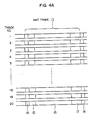
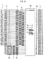
- Fig. 7 shows a data record pattern on the magnetic tape recorded in the present embodiment.
- the L-channel and R-channel even data (L o , R 8 ), (L 2 , R 10 ), ..., (R s , L 14 ) or odd data (R 1 , Lg), (R 3 , L n ), ..., (L 7 , R 15 ) are arranged on each of the first to sixteenth tracks except the edge tracks, and parity data (words) (Q 1 , Q 5 ), (Q 3 , Q 7 ), (Q 0 , Q 4 ), (Q 2 , Q s ) are arranged on the seventeenth to twentieth tracks on the edges of the tape. In the reproducing mode, one block is constructed by those data.
- the odd data and the even data are spaced by 30 block length in the tape transport direction so that they are completely separated.
- the parity data (Q 0 ⁇ Q 7 ) which are selectively delayed are obliquely and dispersely arranged with respect to the track.
- the data are also selectively delayed and obliquely distributed with respect to the track.
- first half of the even data (L 0 , L 2 , L 4 , L 6 ) and record half of the odd data (Lg, L " , L 13 , L, s ) are distributed in the first to eighth tracks in the center of the tape
- second half of the even data (L s , L 10 , L, 2 , L 14 ) and first half of the odd data (L,, L 3 , L 5 , L 7 ) are distributed in the ninth to sixteenth tracks in the edge of the tape.
- the right channel sample data R 0 ⁇ R 15 are distributed symmetrically to L 0 ⁇ L 15 with respect to the tracks of those two groups.
- the distance between the sample data which are adjacent to each other in the original time sequence for example, the distance between the even data L o and the odd data L, after the separation can be adjusted by the distribution of the parity data Q 0 ⁇ Q 7 . Accordingly, the adjustment for the audio data is not necessary.
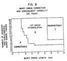
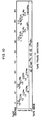
- Fig. 8 illustrates the burst error correction capability for the 20 . tracks.
- An ordinate represents the number of occurrence of burst errors
- an abscissa represents a burst error length (in mm)
- an area A represents a correctable area
- an area B represents a first order interpolation (i.e. concealment) area
- an area C represents an incorrectable area on correction and concealment.
- the L-channel data and the R-channel data are recorded in each track so that the burst error in a specific track is distributed to both channels.
- the parities are arranged in the tracks near the tape edge having a low error rate and the PCM signals are recorded in the inner tracks so that a probability or error of the PCM signals is reduced.
- the odd data and the even data are separated and the adjacent data, for example, the data L o and L, are arranged to be spaced as much as possible in the tape transport direction and the tape width direction so that the error correction capability to the burst error is enhanced.
- Fig. 9 shows other embodiment of the present invention for 10-track record.
- the only difference from Fig. 1 is a track distribution means 3.
- the even data are arranged on the odd tracks and the odd data are arranged on the even track.
- Fig. 10 shows a record pattern on the tape in the embodiment of Fig. 9. The delays are equal to those shown in Fig. 7.
- the interleave method of the present invention can be applied to the ten- track record without reducing the error correction capability by merely changing the track distribution means.
Landscapes
- Engineering & Computer Science (AREA)
- Signal Processing (AREA)
- Multimedia (AREA)
- Signal Processing For Digital Recording And Reproducing (AREA)
Claims (9)
Applications Claiming Priority (2)
| Application Number | Priority Date | Filing Date | Title |
|---|---|---|---|
| JP151210/84 | 1984-07-23 | ||
| JP59151210A JPH07111815B2 (ja) | 1984-07-23 | 1984-07-23 | デイジタル信号記録方式 |
Publications (3)
| Publication Number | Publication Date |
|---|---|
| EP0169540A2 EP0169540A2 (fr) | 1986-01-29 |
| EP0169540A3 EP0169540A3 (en) | 1987-02-04 |
| EP0169540B1 true EP0169540B1 (fr) | 1990-01-03 |
Family
ID=15513640
Family Applications (1)
| Application Number | Title | Priority Date | Filing Date |
|---|---|---|---|
| EP85109200A Expired - Lifetime EP0169540B1 (fr) | 1984-07-23 | 1985-07-23 | Procédé et dispositif d'enregistrement et de reproduction d'un signal numérique avec une tête fixe |
Country Status (5)
| Country | Link |
|---|---|
| US (1) | US4646170A (fr) |
| EP (1) | EP0169540B1 (fr) |
| JP (1) | JPH07111815B2 (fr) |
| KR (1) | KR900000630B1 (fr) |
| DE (1) | DE3575224D1 (fr) |
Families Citing this family (30)
| Publication number | Priority date | Publication date | Assignee | Title |
|---|---|---|---|---|
| EP0188627B1 (fr) * | 1984-07-21 | 1990-10-10 | Sony Corporation | Dispositif d'enregistrement et/ou reproduction de cartes optiques |
| JPS61154227A (ja) * | 1984-12-26 | 1986-07-12 | Mitsubishi Electric Corp | 2段符号化方法 |
| FR2583240B1 (fr) * | 1985-06-05 | 1994-02-04 | France Telediffusion | Procede de transmission en blocs de mots d'information numerique |
| JPH0831250B2 (ja) * | 1986-01-23 | 1996-03-27 | 三菱電機株式会社 | Pcm記録装置 |
| DE3688693T2 (de) * | 1985-10-11 | 1993-11-11 | Mitsubishi Electric Corp | PCM-Aufnahme- und -Wiedergabegerät. |
| JPS62177768A (ja) * | 1986-01-31 | 1987-08-04 | Sony Corp | エラ−訂正装置 |
| US4750167A (en) * | 1986-10-20 | 1988-06-07 | The Grass Valley Group, Inc. | Digital audio transmission system |
| DE3735979A1 (de) * | 1986-10-24 | 1988-04-28 | Mitsubishi Electric Corp | Pcm-signalwiedergabevorrichtung mit fehler/loeschkorrekturschaltung |
| US4864572A (en) * | 1987-05-26 | 1989-09-05 | Rechen James B | Framing bitstreams |
| JPH0193933A (ja) * | 1987-10-06 | 1989-04-12 | Sony Corp | エラー訂正符号化装置 |
| JP2563389B2 (ja) * | 1987-11-13 | 1996-12-11 | 松下電器産業株式会社 | 誤り検出訂正方法 |
| US4942551A (en) * | 1988-06-24 | 1990-07-17 | Wnm Ventures Inc. | Method and apparatus for storing MIDI information in subcode packs |
| NL9000039A (nl) * | 1990-01-08 | 1991-08-01 | Philips Nv | Digitaal transmissiesysteem, zender en ontvanger te gebruiken in het transmissiesysteem en registratiedrager verkregen met de zender in de vorm van een optekeninrichting. |
| ES2103719T3 (es) * | 1990-01-18 | 1997-10-01 | Philips Electronics Nv | Dispositivo de almacenamiento reversible de datos digitales sobre un medio multipista, dispositivo descodificador aparato de reproduccion de informacion para utilizar con dicho medio, y soporte de almacenamiento para utilizar con dicho dispositivo de almacenamiento, con dicho |
| US5140596A (en) * | 1990-02-20 | 1992-08-18 | Eastman Kodak Company | High speed encoder for non-systematic codes |
| KR950009383B1 (ko) * | 1990-06-29 | 1995-08-21 | 마쯔시다 덴기 산교 가부시기가이샤 | 디지틀음성신호기록방법 |
| US5263030A (en) * | 1991-02-13 | 1993-11-16 | Digital Equipment Corporation | Method and apparatus for encoding data for storage on magnetic tape |
| US5363250A (en) * | 1991-07-31 | 1994-11-08 | U.S. Philips Corporation | Prerecorded record carrier |
| JPH05176275A (ja) * | 1991-11-29 | 1993-07-13 | Minolta Camera Co Ltd | フィルムプレーヤ |
| US5369652A (en) * | 1993-06-14 | 1994-11-29 | International Business Machines Corporation | Error detection and correction having one data format recordable on record media using a diverse number of concurrently recorded tracks |
| US5485321A (en) * | 1993-12-29 | 1996-01-16 | Storage Technology Corporation | Format and method for recording optimization |
| DE69524573T2 (de) * | 1994-12-09 | 2002-08-14 | Koninkl Philips Electronics Nv | Mehrspur-aufzeichnungs-/wiedergabeanordnung |
| JP3185877B2 (ja) * | 1998-09-21 | 2001-07-11 | 日本電気株式会社 | テープ再生装置および方法 |
| JP4722528B2 (ja) * | 2005-03-31 | 2011-07-13 | Toto株式会社 | トイレ装置 |
| US7624328B2 (en) * | 2005-08-04 | 2009-11-24 | Quantum Corporation | Data error detection during media write |
| TW200738941A (en) | 2006-02-10 | 2007-10-16 | Toto Ltd | Sanitary washing toilet seat device, and toilet device |
| JP4836602B2 (ja) * | 2006-02-21 | 2011-12-14 | Toto株式会社 | 衛生洗浄便座装置及びトイレ装置 |
| US8208213B2 (en) * | 2010-06-02 | 2012-06-26 | Lsi Corporation | Systems and methods for hybrid algorithm gain adaptation |
| US9477552B1 (en) * | 2015-11-19 | 2016-10-25 | International Business Machines Corporation | Priority-based decoding |
| US9837117B2 (en) * | 2015-11-19 | 2017-12-05 | International Business Machines Corporation | Track-dependent decoding |
Family Cites Families (18)
| Publication number | Priority date | Publication date | Assignee | Title |
|---|---|---|---|---|
| GB1599156A (en) * | 1976-12-24 | 1981-09-30 | Indep Broadcasting Authority | Recording digital signals |
| JPS53142208A (en) * | 1977-05-18 | 1978-12-11 | Teac Corp | Method of recording pcm signal |
| US4211997A (en) * | 1978-11-03 | 1980-07-08 | Ampex Corporation | Method and apparatus employing an improved format for recording and reproducing digital audio |
| JPS574629A (en) * | 1980-05-21 | 1982-01-11 | Sony Corp | Data transmitting method capable of correction of error |
| JPS5736410A (en) * | 1980-08-14 | 1982-02-27 | Sony Corp | Error correcting method for multitrack recording |
| JPS5792411A (en) * | 1980-11-28 | 1982-06-09 | Sony Corp | Pcm signal processor |
| JPS5794911A (en) * | 1980-12-01 | 1982-06-12 | Sony Corp | Pcm signal processor |
| US4380071A (en) * | 1981-02-02 | 1983-04-12 | Sony Corporation | Method and apparatus for preventing errors in PCM signal processing apparatus |
| JPS57183609A (en) * | 1981-05-07 | 1982-11-12 | Victor Co Of Japan Ltd | Magnetic recording system of digital signal |
| JPS5845613A (ja) * | 1981-09-11 | 1983-03-16 | Hitachi Ltd | Pcmレコ−ダ |
| JPS5864608A (ja) * | 1981-10-15 | 1983-04-18 | Victor Co Of Japan Ltd | デイジタル信号記録再生方式 |
| JPH07109645B2 (ja) * | 1982-04-16 | 1995-11-22 | 株式会社日立製作所 | マルチトラックpcmレコーダシステム |
| CA1196106A (fr) * | 1982-04-28 | 1985-10-29 | Tsuneo Furuya | Methode et dispositif de correction d'erreurs |
| JPH07118159B2 (ja) * | 1982-12-06 | 1995-12-18 | ソニー株式会社 | Pcm信号記録方法 |
| JPH0661156B2 (ja) * | 1983-05-21 | 1994-08-10 | ソニー株式会社 | エラ−訂正のための符号化方法 |
| JPH07118160B2 (ja) * | 1983-06-18 | 1995-12-18 | ソニー株式会社 | ディジタル情報信号の記録方法 |
| JPS60247866A (ja) * | 1984-05-22 | 1985-12-07 | Sony Corp | デイジタルテ−プレコ−ダ |
| JPS6116072A (ja) * | 1984-07-02 | 1986-01-24 | Mitsubishi Electric Corp | デイジタル記録再生装置 |
-
1984
- 1984-07-23 JP JP59151210A patent/JPH07111815B2/ja not_active Expired - Lifetime
-
1985
- 1985-07-19 KR KR1019850005150A patent/KR900000630B1/ko not_active IP Right Cessation
- 1985-07-22 US US06/757,448 patent/US4646170A/en not_active Expired - Fee Related
- 1985-07-23 DE DE8585109200T patent/DE3575224D1/de not_active Expired - Lifetime
- 1985-07-23 EP EP85109200A patent/EP0169540B1/fr not_active Expired - Lifetime
Also Published As
| Publication number | Publication date |
|---|---|
| EP0169540A3 (en) | 1987-02-04 |
| EP0169540A2 (fr) | 1986-01-29 |
| KR900000630B1 (ko) | 1990-02-01 |
| DE3575224D1 (de) | 1990-02-08 |
| KR860001410A (ko) | 1986-02-26 |
| JPS6132267A (ja) | 1986-02-14 |
| JPH07111815B2 (ja) | 1995-11-29 |
| US4646170A (en) | 1987-02-24 |
Similar Documents
| Publication | Publication Date | Title |
|---|---|---|
| EP0169540B1 (fr) | Procédé et dispositif d'enregistrement et de reproduction d'un signal numérique avec une tête fixe | |
| EP0127687B1 (fr) | Procede d'enregistrement de signaux a modulation par impulsions codees | |
| EP0155664B1 (fr) | Procédé et système d'enregistrement et de reproduction PCM à tête rotative | |
| KR920008229B1 (ko) | 디지탈정보신호의 기록방법 | |
| US4866636A (en) | Method and apparatus for uniformly encoding data occurring with different word lengths | |
| EP0074644B1 (fr) | Dispositif d'enregistrement et de reproduction de signaux MIC selon un format d'enregistrement de données, immunisé contre les effacements | |
| EP0301399B1 (fr) | Bande magnétique comprenant un enregistrement digital et procédé concu pour sa fabrication | |
| EP0093969B1 (fr) | Méthode, dispositif et moyen d'enregistrement pour la correction d'erreurs | |
| US4630272A (en) | Encoding method for error correction | |
| US4429390A (en) | Digital signal transmitting system | |
| GB2061575A (en) | Method and apparatus for encoding low redundancy check words from source data | |
| GB2060227A (en) | Method and apparatus for communicating digital information words by error-correction encoding and decoding | |
| US5491590A (en) | Rotary head recording and playback apparatus and method | |
| EP0213961B1 (fr) | Méthodes et appareil d'enregistrement et/ou de reproduction de données digitales | |
| US5459621A (en) | Method and apparatus for rotary-head type signal recording and reproducing of digital video/audio signals | |
| JPH0377589B2 (fr) | ||
| KR970008641B1 (ko) | 부호화 디지탈 신호의 기록 방법 | |
| KR920008226B1 (ko) | 디지탈테이프레코더 | |
| JPH0634311B2 (ja) | デイジタル情報信号の記録方法 | |
| JPH0810540B2 (ja) | デイジタル信号記録方式 | |
| JPH0287372A (ja) | デイジタル再生装置 |
Legal Events
| Date | Code | Title | Description |
|---|---|---|---|
| PUAI | Public reference made under article 153(3) epc to a published international application that has entered the european phase |
Free format text: ORIGINAL CODE: 0009012 |
|
| 17P | Request for examination filed |
Effective date: 19850723 |
|
| AK | Designated contracting states |
Designated state(s): DE FR GB IT NL |
|
| PUAL | Search report despatched |
Free format text: ORIGINAL CODE: 0009013 |
|
| AK | Designated contracting states |
Kind code of ref document: A3 Designated state(s): DE FR GB IT NL |
|
| 17Q | First examination report despatched |
Effective date: 19880427 |
|
| GRAA | (expected) grant |
Free format text: ORIGINAL CODE: 0009210 |
|
| AK | Designated contracting states |
Kind code of ref document: B1 Designated state(s): DE FR GB IT NL |
|
| REF | Corresponds to: |
Ref document number: 3575224 Country of ref document: DE Date of ref document: 19900208 |
|
| ITF | It: translation for a ep patent filed |
Owner name: MODIANO & ASSOCIATI S.R.L. |
|
| ET | Fr: translation filed | ||
| ITTA | It: last paid annual fee | ||
| PGFP | Annual fee paid to national office [announced via postgrant information from national office to epo] |
Ref country code: NL Payment date: 19900731 Year of fee payment: 6 |
|
| PLBE | No opposition filed within time limit |
Free format text: ORIGINAL CODE: 0009261 |
|
| STAA | Information on the status of an ep patent application or granted ep patent |
Free format text: STATUS: NO OPPOSITION FILED WITHIN TIME LIMIT |
|
| 26N | No opposition filed | ||
| PG25 | Lapsed in a contracting state [announced via postgrant information from national office to epo] |
Ref country code: NL Effective date: 19920201 |
|
| NLV4 | Nl: lapsed or anulled due to non-payment of the annual fee | ||
| PGFP | Annual fee paid to national office [announced via postgrant information from national office to epo] |
Ref country code: FR Payment date: 19930528 Year of fee payment: 9 |
|
| PGFP | Annual fee paid to national office [announced via postgrant information from national office to epo] |
Ref country code: GB Payment date: 19930713 Year of fee payment: 9 |
|
| PGFP | Annual fee paid to national office [announced via postgrant information from national office to epo] |
Ref country code: DE Payment date: 19930825 Year of fee payment: 9 |
|
| PG25 | Lapsed in a contracting state [announced via postgrant information from national office to epo] |
Ref country code: GB Effective date: 19940723 |
|
| GBPC | Gb: european patent ceased through non-payment of renewal fee |
Effective date: 19940723 |
|
| PG25 | Lapsed in a contracting state [announced via postgrant information from national office to epo] |
Ref country code: FR Effective date: 19950331 |
|
| PG25 | Lapsed in a contracting state [announced via postgrant information from national office to epo] |
Ref country code: DE Effective date: 19950401 |
|
| REG | Reference to a national code |
Ref country code: FR Ref legal event code: ST |