EP0165327A1 - Führungsvorrichtung für Schussfadeneintragsorgane für Webmaschinen, insbesondere für Greiferprojektil-Webmaschinen - Google Patents
Führungsvorrichtung für Schussfadeneintragsorgane für Webmaschinen, insbesondere für Greiferprojektil-Webmaschinen Download PDFInfo
- Publication number
- EP0165327A1 EP0165327A1 EP84107018A EP84107018A EP0165327A1 EP 0165327 A1 EP0165327 A1 EP 0165327A1 EP 84107018 A EP84107018 A EP 84107018A EP 84107018 A EP84107018 A EP 84107018A EP 0165327 A1 EP0165327 A1 EP 0165327A1
- Authority
- EP
- European Patent Office
- Prior art keywords
- guide
- projectile
- loom
- leg
- reed
- Prior art date
- Legal status (The legal status is an assumption and is not a legal conclusion. Google has not performed a legal analysis and makes no representation as to the accuracy of the status listed.)
- Granted
Links
- 238000009941 weaving Methods 0.000 claims abstract description 8
- 238000003780 insertion Methods 0.000 claims abstract description 3
- 230000037431 insertion Effects 0.000 claims abstract description 3
- 235000014676 Phragmites communis Nutrition 0.000 claims description 9
- 210000000056 organ Anatomy 0.000 claims 1
- 230000000295 complement effect Effects 0.000 abstract description 2
- 230000007704 transition Effects 0.000 description 1
Images
Classifications
-
- D—TEXTILES; PAPER
- D03—WEAVING
- D03D—WOVEN FABRICS; METHODS OF WEAVING; LOOMS
- D03D47/00—Looms in which bulk supply of weft does not pass through shed, e.g. shuttleless looms, gripper shuttle looms, dummy shuttle looms
- D03D47/27—Drive or guide mechanisms for weft inserting
- D03D47/277—Guide mechanisms
Definitions
- the invention relates to a guide device for weft insertion elements for weaving machines, in particular for rapier projectile weaving machines, with longitudinally alternating guide supports and guide hooks, each of which form a guide tooth complementarily in pairs, and wherein a guide support consists of a longer one, closer to the reed and a shorter one, from the reed further away leg exists.
- CH-PS 465 5211 It occurs in the known projectile guiding device (CH-PS 465 521) that when the device is immersed in the shed, individual warp threads cross within the guide tooth, which is open at the top. The warp thread is locally overstretched.
- the invention has for its object to provide a guide device of the type defined in which a crossing of a warp thread of the type mentioned above is not possible and thus its overextension is avoided.
- This object is achieved according to the invention by the features specified in the characterizing part of claim 1.
- a drawer 1 carries a projectile guide device 2, which consists of a number of guide supports 3 and guide hooks 4, which are cast in a block 5.
- the guide supports and guide hooks alternate with one another in the longitudinal direction of the guide device and each form a complementary guide tooth in pairs.
- the guide support 3 and the guide hooks 4 together form a guide channel 8 for a projectile 9, which is a weft thread 10 drags with him.
- the drawer 1 with the guide device 2 is located before the weft thread 10 stops by a reed 11 in a shed 12, which is formed by the warp threads 13 and 14.
- the drawer 1 moves the projectile guide device 2 between the fully drawn and the dashed position 2 '.
- the contours of a guide support 15a or a guide hook 15b of a guide tooth 15 are first drawn in with dash-dotted lines in FIG. 2.
- the guide support 15a consists of a longer leg 15c closer to the reed and a shorter leg 15d located farther from the reed, with a valley 15e as a transition between the two.
- the projectile is supported in three ways: on the inside of the longer leg 15c, on the shorter leg 15d and on the upper inner edge of the guide hook 15b.
- the guide hook 15b is mainly marked through a long, narrow neck 15f, so that a large clear width-16 remains within the guide tooth.
- An adjacent guide tooth is designated 17.
- a warp thread 19 is located in an alley 18 of the guide tooth 15, and a warp thread 21 is located in an alley 20 between the guide tooth 15 and the next guide tooth 17 2 it can happen that the warp thread 21 from the alley 20 hooks behind the shorter leg 15d of the guide support 15a and passes through the tail 15e into the alley 18, where the correctly running warp thread 19 is located.
- the deviating warp thread is shown in dash-dot lines and designated 21 '. This leads to an undesirable overstretching of the different warp thread.
- the shorter leg 15d of the guide support 15a is removed from each guide tooth 15, so that only one single-leg guide support 15c remains for the projectile near the reed.
- the neck 15f of the guide hook 15b is widened towards the guide channel 8 and has a support surface 22 for the projectile. Both measures prevent the warp thread from being overstretched when it jumps into an adjacent alley.
Landscapes
- Engineering & Computer Science (AREA)
- Textile Engineering (AREA)
- Looms (AREA)
Abstract
Description
- Die Erfindung betrifft eine Führungsvorrichtung für Schussfadeneintragsorgane für Webmaschinen, insbesondere für Greiferprojektil-Webmaschinen, mit sich in Längsrichtung abwechselnden Führungsstützen und Führungshaken, die jeweils paarweise komplementär einen Führungszahn bilden, und wobei eine Führungsstütze aus einem längeren, dem Riet nähergelegenen und einem kürzeren, vom Riet weiter entfernt gelegenen Schenkel besteht.
- Es kommt bei der bekannten Projektilführungsvorrichtung (CH-PS 465 521) vor, dass beim Eintauchen der Vorrichtung ins Webfach einzelne Kettfäden innerhalb des nach oben offenen Führungszahnes kreuzen. Der Kettfaden wird dabei örtlich überdehnt.
- Der Erfindung liegt die Aufgabe zugrunde eine Führungsvorrichtung der eingangs definierten Art zu schaffen bei der ein Kreuzen eines Kettfadens der obenerwähnten Art nicht möglich ist und somit seine Ueberdehnung vermieden wird. Diese Aufgabe wird gemäss der Erfindung durch die im Kennzeichen des Anspruchs 1 angegebenen Merkmale gelöst.
- Ein Ausführungsbeispiel des Erfindungsgegenstandes ist nachfolgend anhand der Zeichnung beschrieben. Es ist:
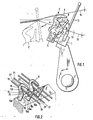
- Fig. i eine Seitenansicht einer Projektilführungsvorrichtung gemäss der Erfindung;
- Fig. 2 eine Draufsicht in der Perspektive eines Teiles der Vorrichtung.
- Nach Fig. l trägt eine Lade 1 eine Projektilführungsvorrichtung 2, die aus einer Anzahl Führungsstützen 3 und Führungshaken 4 besteht, die in einem Block 5 eingegossen sind. Wie deutlich in Fig. 2 zu sehen ist, wechseln die Führungsstützen und Führungshaken einander in Längsrichtung der Führungsvorrichtung ab und bilden jeweils paarweise komplementär einen Führungszahn 6. Die Führungsstütze 3 und die Führungshaken 4 bilden zusammen einen Führungskanal 8 für ein Projektil 9, das einen Schussfaden 10 mit sich schleppt. Die Lade 1 mit der Führungsvorrichtung 2 befindet sich vor dem Anschlag des Schussfadens 10 durch ein Riet 11 in einem Webfach 12, das durch die Kettfäden 13 und 14 gebildet wird. Die Lade 1 bewegt die Projektilführungsvorrichtung 2 zwischen der voll gezeichneten und der gestrichelt gezeichneten Lage 2'.
- Zum besseren Verständnis des Erfindungsgegenstandes sind zunächst in Fig. 2 mit strichpunktierten Linien die Konturen einer Führungsstütze 15a bzw. eines Führungshakens 15b eines Führungszahnes 15 gemäss dem Stand der Technik eingezeichnet. Wie ersichtlich besteht die Führungsstütze 15a aus einem längeren, dem Riet nähergelegenen Schenkel 15c und einem kürzeren, vom Riet entfernter gelegenen Schenkel 15d, mit einem Tal 15e als Uebergang zwischen beiden. Das Projektil wird dreifach gestützt: An der Innenseite des längeren Schenkels 15c, am kürzeren Schenkel 15d und an der oberen Innenkante des Führungshakens 15b. Der Führungshaken 15b ist in der Hauptsache gekennzeichnet durch einen langen, schmalen Hals 15f, so dass eine grosse lichte Weite-16 innerhalb des Führungszahnes verblieben ist. Ein benachbarter Führungszahn ist mit 17 bezeichnet. In einer Gasse 18 des Führungszahnes 15 befindet sich ein Kettfaden 19, in einer Gasse 20 zwischen dem Führungszahn 15 und dem nächsten Führungszahn 17 befindet sich ein Kettfaden 21. Bei der Hin- und Herbewegung der Lade 1 bzw. der Ein- und Austauchbewegung der Führungsvorrichtung 2 kann es vorkommen, dass der Kettfaden 21 aus der Gasse 20 sich hinter dem kürzeren Schenkel 15d der Führungsstütze 15a verhakt und durch das Tail 15e in die Gasse 18 gelangt, wo sich der korrekt verlaufende Kettfaden 19 befindet. Der abweichende Kettfaden ist strichpunktiert eingezeichnet und mit 21' bezeichnet. Dies führt zu einem unerwünschten Ueberdehnen des abweichenden Kettfadens.
- Erfindungsgemäss ist bei jedem Führungszahn 15 einerseits der kürzere Schenkel 15d der Führungsstütze 15a entfernt, so dass nur eine einschenkelige Führungsstütze 15c nahe dem Riet für das Projektil verblieben ist. Anderseits ist der Hals 15f des Führungshakens 15b zum Führungskanal 8 hin verbreitert und weist eine Stützfläche 22 für das Projektil auf. Durch beide Massnahmen wird verhindert, dass beim Ueberspringen eines Kettfadens in eine benachbarte Gasse dieser überdehnt wird.
- Obschon die Erfindung für Greiferprojektil-Webmaschinen beschrieben ist, ist sie selbstverständlich auch für andere Webmaschinenarten verwendbar, z.B. für Handgreiferwebmaschinen.
Claims (1)
Priority Applications (3)
| Application Number | Priority Date | Filing Date | Title |
|---|---|---|---|
| EP84107018A EP0165327B1 (de) | 1984-06-19 | 1984-06-19 | Führungsvorrichtung für Schussfadeneintragsorgane für Webmaschinen, insbesondere für Greiferprojektil-Webmaschinen |
| DE8484107018T DE3473481D1 (en) | 1984-06-19 | 1984-06-19 | Guideway for the weft inserter of a loom, especially for a dummy shuttle loom |
| US06/741,002 US4628968A (en) | 1984-06-19 | 1985-06-04 | Guide for a weft-picking element |
Applications Claiming Priority (1)
| Application Number | Priority Date | Filing Date | Title |
|---|---|---|---|
| EP84107018A EP0165327B1 (de) | 1984-06-19 | 1984-06-19 | Führungsvorrichtung für Schussfadeneintragsorgane für Webmaschinen, insbesondere für Greiferprojektil-Webmaschinen |
Publications (2)
| Publication Number | Publication Date |
|---|---|
| EP0165327A1 true EP0165327A1 (de) | 1985-12-27 |
| EP0165327B1 EP0165327B1 (de) | 1988-08-17 |
Family
ID=8192001
Family Applications (1)
| Application Number | Title | Priority Date | Filing Date |
|---|---|---|---|
| EP84107018A Expired EP0165327B1 (de) | 1984-06-19 | 1984-06-19 | Führungsvorrichtung für Schussfadeneintragsorgane für Webmaschinen, insbesondere für Greiferprojektil-Webmaschinen |
Country Status (3)
| Country | Link |
|---|---|
| US (1) | US4628968A (de) |
| EP (1) | EP0165327B1 (de) |
| DE (1) | DE3473481D1 (de) |
Cited By (2)
| Publication number | Priority date | Publication date | Assignee | Title |
|---|---|---|---|---|
| EP0402285A1 (de) * | 1989-06-09 | 1990-12-12 | S.A. Saurer Diederichs | Führungsvorrichtung für Schussfadeneintragsorgane für eine schützenlose Webmaschine |
| EP0898000A3 (de) * | 1995-02-07 | 2000-02-23 | Picanol N.V. | Greiferwebmaschine mit Führungdmitteln zum Führen eines Greiferbandes und/oder eines Greifers |
Families Citing this family (3)
| Publication number | Priority date | Publication date | Assignee | Title |
|---|---|---|---|---|
| BE1004305A3 (nl) * | 1989-07-06 | 1992-10-27 | Picanol Nv | Grijperweefmachine met lansgeleiding. |
| DE4308243A1 (de) * | 1993-03-11 | 1994-09-15 | Juergens Masch Gmbh & Co | Projektil-Breitwebmaschine |
| DE10346225A1 (de) * | 2003-09-23 | 2005-05-19 | Picanol N.V. | Führungselement für ein Greiferband |
Citations (3)
| Publication number | Priority date | Publication date | Assignee | Title |
|---|---|---|---|---|
| DE1801044A1 (de) * | 1967-12-08 | 1969-07-03 | Sulzer Ag | Fuehrungseinrichtung fuer das Schussfadeneintragsorgan einer Webmaschine |
| DE1801043A1 (de) * | 1967-12-08 | 1969-11-06 | Sulzer Ag | Fuehrungselement fuer das Schussfadeneintragsorgan einer Webmaschine |
| EP0101777A1 (de) * | 1982-08-26 | 1984-03-07 | GebràDer Sulzer Aktiengesellschaft | Webmaschine mit einer Schmiervorrichtung für das Schusseintragsorgan |
Family Cites Families (3)
| Publication number | Priority date | Publication date | Assignee | Title |
|---|---|---|---|---|
| US3556163A (en) * | 1968-12-06 | 1971-01-19 | Sulzer Ag | Guide for weft-picking means in a loom |
| US3705605A (en) * | 1970-12-15 | 1972-12-12 | Visesojuzny Nii Textilnogo Leg | Fabric forming device for weaving looms |
| CH648616A5 (de) * | 1980-12-02 | 1985-03-29 | Sulzer Ag | Fuehrungszahn zur bildung eines schusseintragskanales einer webmaschine. |
-
1984
- 1984-06-19 EP EP84107018A patent/EP0165327B1/de not_active Expired
- 1984-06-19 DE DE8484107018T patent/DE3473481D1/de not_active Expired
-
1985
- 1985-06-04 US US06/741,002 patent/US4628968A/en not_active Expired - Fee Related
Patent Citations (3)
| Publication number | Priority date | Publication date | Assignee | Title |
|---|---|---|---|---|
| DE1801044A1 (de) * | 1967-12-08 | 1969-07-03 | Sulzer Ag | Fuehrungseinrichtung fuer das Schussfadeneintragsorgan einer Webmaschine |
| DE1801043A1 (de) * | 1967-12-08 | 1969-11-06 | Sulzer Ag | Fuehrungselement fuer das Schussfadeneintragsorgan einer Webmaschine |
| EP0101777A1 (de) * | 1982-08-26 | 1984-03-07 | GebràDer Sulzer Aktiengesellschaft | Webmaschine mit einer Schmiervorrichtung für das Schusseintragsorgan |
Cited By (3)
| Publication number | Priority date | Publication date | Assignee | Title |
|---|---|---|---|---|
| EP0402285A1 (de) * | 1989-06-09 | 1990-12-12 | S.A. Saurer Diederichs | Führungsvorrichtung für Schussfadeneintragsorgane für eine schützenlose Webmaschine |
| FR2648161A1 (fr) * | 1989-06-09 | 1990-12-14 | Saurer Diederichs Sa | Dispositif de support et de guidage pour organes d'insertion mecanique de la trame, dans une machine a tisser sans navette |
| EP0898000A3 (de) * | 1995-02-07 | 2000-02-23 | Picanol N.V. | Greiferwebmaschine mit Führungdmitteln zum Führen eines Greiferbandes und/oder eines Greifers |
Also Published As
| Publication number | Publication date |
|---|---|
| DE3473481D1 (en) | 1988-09-22 |
| US4628968A (en) | 1986-12-16 |
| EP0165327B1 (de) | 1988-08-17 |
Similar Documents
| Publication | Publication Date | Title |
|---|---|---|
| EP0165327B1 (de) | Führungsvorrichtung für Schussfadeneintragsorgane für Webmaschinen, insbesondere für Greiferprojektil-Webmaschinen | |
| DE2616910A1 (de) | Vorrichtung zur bildung einer dreherbindungs-webkante auf webstuehlen | |
| EP0214322B1 (de) | Drehervorrichtung für Webmaschinen | |
| EP0199880A1 (de) | Schussfadeneintragsvorrichtung einer Webmaschine, insbesondere einer Greiferprojektil-Webmaschine | |
| EP0165326B1 (de) | Führungsvorrichtung für Schussfadeneintragsorgane für Webmaschinen, insbesondere Greiferprojektil-Webmaschinen | |
| DE2926018C2 (de) | Vorrichtung zur Programmsteuerung der Versatzbewegungen von Legeschienen an Kettenwirkmaschinen | |
| DE3104094A1 (de) | "strahlduese mit abgeschirmt vorgesehener spritzoeffnung, geeignet fuer eine schuetzenlose webmaschine" | |
| EP0199881A1 (de) | Schussfadeneintragsvorrichtung einer Greiferprojektil-Webmaschine | |
| CH641847A5 (de) | Vorrichtung zum bilden einer mit einer bindung versehenen gewebekante, insbesondere bei schuetzenlosen webmaschinen. | |
| DE1535611C3 (de) | Verfahren zur Herstellung von Ge webeleisten und Vorrichtung zu seiner Durchfuhrung | |
| EP0053217B1 (de) | Führungszahn zur Bildung eines Schusseintragskanales einer Webmaschine | |
| DE2825679C2 (de) | Vorrichtung zum Schusseintrag an Webmaschinen mittels eines strömenden Mediums | |
| DE1801044A1 (de) | Fuehrungseinrichtung fuer das Schussfadeneintragsorgan einer Webmaschine | |
| CH648616A5 (de) | Fuehrungszahn zur bildung eines schusseintragskanales einer webmaschine. | |
| DE572534C (de) | Vorrichtung fuer mechanische Webstuehle zur Herstellung von Drehergeweben in Kreuzdreherbindung | |
| DE3034120A1 (de) | Eintragskanal fuer eine duesenwebmaschine | |
| EP0570330B1 (de) | Reihenfachwebmaschine | |
| DE2707682C2 (de) | Kanteneinleger fuer einen schuetzenlosen webstuhl | |
| EP0188645B1 (de) | Webmaschine | |
| DE1199707B (de) | Lamellenkamm fuer Webstuehle mit pneumatischer Eintragung des Schussfadens | |
| DE558220C (de) | Vorrichtung zum Auswechseln des leeren Schuetzens bei Webstuehlen | |
| DE2204956C3 (de) | Nadelwebmaschine | |
| CH670461A5 (de) | ||
| DE666895C (de) | Vorrichtung zum Weben auf Webstuehlen mit einem zusaetzlichen Anschlagkamm | |
| DE604342C (de) | Dreherhalblitze |
Legal Events
| Date | Code | Title | Description |
|---|---|---|---|
| PUAI | Public reference made under article 153(3) epc to a published international application that has entered the european phase |
Free format text: ORIGINAL CODE: 0009012 |
|
| 17P | Request for examination filed |
Effective date: 19850420 |
|
| AK | Designated contracting states |
Designated state(s): AT BE CH DE FR GB IT LI LU NL SE |
|
| RBV | Designated contracting states (corrected) |
Designated state(s): CH DE FR GB IT LI |
|
| 17Q | First examination report despatched |
Effective date: 19870512 |
|
| ITF | It: translation for a ep patent filed | ||
| GRAA | (expected) grant |
Free format text: ORIGINAL CODE: 0009210 |
|
| AK | Designated contracting states |
Kind code of ref document: B1 Designated state(s): CH DE FR GB IT LI |
|
| GBT | Gb: translation of ep patent filed (gb section 77(6)(a)/1977) | ||
| REF | Corresponds to: |
Ref document number: 3473481 Country of ref document: DE Date of ref document: 19880922 |
|
| ET | Fr: translation filed | ||
| PGFP | Annual fee paid to national office [announced via postgrant information from national office to epo] |
Ref country code: GB Payment date: 19890531 Year of fee payment: 6 |
|
| PGFP | Annual fee paid to national office [announced via postgrant information from national office to epo] |
Ref country code: FR Payment date: 19890614 Year of fee payment: 6 |
|
| PLBE | No opposition filed within time limit |
Free format text: ORIGINAL CODE: 0009261 |
|
| STAA | Information on the status of an ep patent application or granted ep patent |
Free format text: STATUS: NO OPPOSITION FILED WITHIN TIME LIMIT |
|
| ITTA | It: last paid annual fee | ||
| PG25 | Lapsed in a contracting state [announced via postgrant information from national office to epo] |
Ref country code: LI Effective date: 19890630 Ref country code: CH Effective date: 19890630 |
|
| 26N | No opposition filed | ||
| REG | Reference to a national code |
Ref country code: CH Ref legal event code: PL |
|
| PG25 | Lapsed in a contracting state [announced via postgrant information from national office to epo] |
Ref country code: GB Effective date: 19900619 |
|
| GBPC | Gb: european patent ceased through non-payment of renewal fee | ||
| PG25 | Lapsed in a contracting state [announced via postgrant information from national office to epo] |
Ref country code: FR Effective date: 19910228 |
|
| REG | Reference to a national code |
Ref country code: FR Ref legal event code: ST |
|
| PGFP | Annual fee paid to national office [announced via postgrant information from national office to epo] |
Ref country code: DE Payment date: 19930512 Year of fee payment: 10 |
|
| PG25 | Lapsed in a contracting state [announced via postgrant information from national office to epo] |
Ref country code: DE Effective date: 19950301 |