EP0164557B1 - Selbstfahrendes Inspektions- und Wartungsfahrzeug - Google Patents
Selbstfahrendes Inspektions- und Wartungsfahrzeug Download PDFInfo
- Publication number
- EP0164557B1 EP0164557B1 EP85105407A EP85105407A EP0164557B1 EP 0164557 B1 EP0164557 B1 EP 0164557B1 EP 85105407 A EP85105407 A EP 85105407A EP 85105407 A EP85105407 A EP 85105407A EP 0164557 B1 EP0164557 B1 EP 0164557B1
- Authority
- EP
- European Patent Office
- Prior art keywords
- vehicle body
- automotive inspection
- vehicle according
- vehicle
- pipe
- Prior art date
- Legal status (The legal status is an assumption and is not a legal conclusion. Google has not performed a legal analysis and makes no representation as to the accuracy of the status listed.)
- Expired
Links
- 238000007689 inspection Methods 0.000 title claims description 77
- 238000012423 maintenance Methods 0.000 title claims description 35
- 238000003780 insertion Methods 0.000 claims description 10
- 230000037431 insertion Effects 0.000 claims description 10
- 230000002441 reversible effect Effects 0.000 claims description 3
- 230000001360 synchronised effect Effects 0.000 claims 1
- 230000006835 compression Effects 0.000 description 6
- 238000007906 compression Methods 0.000 description 6
- 238000011144 upstream manufacturing Methods 0.000 description 5
- 230000005540 biological transmission Effects 0.000 description 4
- XLYOFNOQVPJJNP-UHFFFAOYSA-N water Substances O XLYOFNOQVPJJNP-UHFFFAOYSA-N 0.000 description 3
- 230000008901 benefit Effects 0.000 description 2
- 238000013461 design Methods 0.000 description 2
- 230000035939 shock Effects 0.000 description 2
- 239000000725 suspension Substances 0.000 description 2
- 239000006096 absorbing agent Substances 0.000 description 1
- 230000009471 action Effects 0.000 description 1
- 238000013459 approach Methods 0.000 description 1
- 230000008859 change Effects 0.000 description 1
- 238000006243 chemical reaction Methods 0.000 description 1
- 238000010276 construction Methods 0.000 description 1
- 230000007547 defect Effects 0.000 description 1
- 238000001514 detection method Methods 0.000 description 1
- 238000011156 evaluation Methods 0.000 description 1
- 230000007246 mechanism Effects 0.000 description 1
- 238000000034 method Methods 0.000 description 1
- 230000003287 optical effect Effects 0.000 description 1
- 230000008569 process Effects 0.000 description 1
- 230000001681 protective effect Effects 0.000 description 1
- 230000001960 triggered effect Effects 0.000 description 1
Images
Classifications
-
- G—PHYSICS
- G01—MEASURING; TESTING
- G01M—TESTING STATIC OR DYNAMIC BALANCE OF MACHINES OR STRUCTURES; TESTING OF STRUCTURES OR APPARATUS, NOT OTHERWISE PROVIDED FOR
- G01M3/00—Investigating fluid-tightness of structures
- G01M3/005—Investigating fluid-tightness of structures using pigs or moles
-
- F—MECHANICAL ENGINEERING; LIGHTING; HEATING; WEAPONS; BLASTING
- F16—ENGINEERING ELEMENTS AND UNITS; GENERAL MEASURES FOR PRODUCING AND MAINTAINING EFFECTIVE FUNCTIONING OF MACHINES OR INSTALLATIONS; THERMAL INSULATION IN GENERAL
- F16L—PIPES; JOINTS OR FITTINGS FOR PIPES; SUPPORTS FOR PIPES, CABLES OR PROTECTIVE TUBING; MEANS FOR THERMAL INSULATION IN GENERAL
- F16L55/00—Devices or appurtenances for use in, or in connection with, pipes or pipe systems
- F16L55/26—Pigs or moles, i.e. devices movable in a pipe or conduit with or without self-contained propulsion means
- F16L55/28—Constructional aspects
-
- G—PHYSICS
- G21—NUCLEAR PHYSICS; NUCLEAR ENGINEERING
- G21C—NUCLEAR REACTORS
- G21C17/00—Monitoring; Testing ; Maintaining
- G21C17/003—Remote inspection of vessels, e.g. pressure vessels
- G21C17/013—Inspection vehicles
-
- Y—GENERAL TAGGING OF NEW TECHNOLOGICAL DEVELOPMENTS; GENERAL TAGGING OF CROSS-SECTIONAL TECHNOLOGIES SPANNING OVER SEVERAL SECTIONS OF THE IPC; TECHNICAL SUBJECTS COVERED BY FORMER USPC CROSS-REFERENCE ART COLLECTIONS [XRACs] AND DIGESTS
- Y02—TECHNOLOGIES OR APPLICATIONS FOR MITIGATION OR ADAPTATION AGAINST CLIMATE CHANGE
- Y02E—REDUCTION OF GREENHOUSE GAS [GHG] EMISSIONS, RELATED TO ENERGY GENERATION, TRANSMISSION OR DISTRIBUTION
- Y02E30/00—Energy generation of nuclear origin
- Y02E30/30—Nuclear fission reactors
Definitions
- the invention relates to a self-propelled inspection and maintenance vehicle for pipeline systems with a vehicle body and a chassis that resiliently supports the vehicle body on the inner surface of the pipeline, the vehicle body being a rigid, tightly closed housing provided with its own power supply, and the chassis at least an electric motor powered by the power supply is assigned.
- a vehicle for inspecting pipelines which has a vehicle body and a chassis which resiliently supports the vehicle body on the inner surface of the pipeline, the vehicle body being formed from a rigid housing provided with its own power supply, and the undercarriage is assigned at least one electric motor fed by the power supply.
- the known vehicle has three wheels at the front and rear, each of which is connected to a drive motor.
- An X-ray inspection device is arranged on the vehicle.
- a wireless command transmission system is used to control the vehicle so that there is no need to drag cables.
- electrical control signals are converted into sound pulses which are transmitted via the pipe wall to a receiver on the vehicle, so that interference in the transmission of commands can result from external influences in the form of mechanical vibrations.
- GB-A 2102565 describes an inspection vehicle for pipes, in which the vehicle body consists of a closed housing which includes an electric motor. At the front, this known inspection vehicle is provided with a light source and light sensors, which respond in particular to obstacles and act on the control device with the drive device of the vehicle in such a way that the drive motor is stopped.
- the drive energy is fed to the inspection vehicle via a cable to be regrinded, cables for controlling the vehicle also being carried along.
- the invention has for its object to provide a self-driving inspection and maintenance vehicle for the inner surfaces of piping systems, the range of which is significantly greater than that of known inspection and maintenance vehicles.
- the vehicle should be free from the disadvantages of a retractable power supply cable or the transmission of control commands by radio or sound waves.
- the object is achieved in that the vehicle body carries a television camera and at least one light source assigned to the viewing area of the television camera and at least one sensor on its front end in the insertion direction into the pipeline is provided for detecting obstacles and that the sensor is connected to a switching device for reversing the drive direction.
- a second solution consists in that the vehicle body carries a television camera and at least one light source assigned to the viewing area of the television camera on its front face in the direction of insertion into the pipeline and that the vehicle body for the timely detection of essential cross-sectional changes, such as e.g. Openings in containers or T-pieces on its front end face are aligned with the illuminated tube wall and are coordinated with the light source and that the detectors are connected to a control logic for reversing the drive direction.
- essential cross-sectional changes such as e.g. Openings in containers or T-pieces on its front end face are aligned with the illuminated tube wall and are coordinated with the light source and that the detectors are connected to a control logic for reversing the drive direction.
- a third solution is characterized in that the vehicle body carries a light source assigned to the front end of the pipe in the direction of insertion into the pipeline, and that the drive direction can be switched via control logic in the event of excessive current consumption by the drive motors.
- a control system does not need a trailing cable, so that the vehicle can travel longer distances than before. Since remote control by means of sound waves or radio is avoided in the inspection and maintenance vehicle according to the invention, the vehicle can also be used in pipelines which are at great depth under water or below the surface of the earth.
- the television camera carried along with the lighting device and the video recorder built into the vehicle body make it possible to extend the inspection trip after the inspection vehicle returns in front of a television viewing device on the basis of the recordings of the video recorder.
- An encapsulated design creates the conditions for inspection and Perform maintenance tasks in water-filled pipe sections.
- the separate pressing of the wheels, which are mounted individually on the shock absorbers, against the inner wall of the tube and the all-wheel drive ensure that the propulsion force is sufficiently high, even for vertical risers.
- the working cylinders make it easier to insert the self-propelled inspection and maintenance vehicle into a one-sided open pipe end by pulling the struts pneumatically or hydraulically against the force of their compression springs against the vehicle body.
- switch-off frame which is axially displaceable on the front end face of the vehicle body in the axis of symmetry makes it possible to sense obstacles in the pipeline and to reverse the direction of travel in good time.
- the light sources which are fed through the openings in the switch-off frame and / or fastened to the switch-off frame and fed by the battery make it possible for the photodetectors which are aligned with the immediately upstream wall area to detect obstacles. In this way, not only raised obstacles, but also T-pieces and openings of the pipe into a container can be recognized and used automatically to reverse the drive. This can, for example, prevent the inspection vehicle from falling into a container when the pipe opens into it.
- the television camera carried along with the lighting device and the video recorder built into the vehicle body make it possible to evaluate the inspection trip after the inspection vehicle returns in front of a television set on the basis of the recordings of the video recorder.
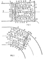
- FIG. 1 shows an inspection and maintenance vehicle 1 according to the invention, which has just been inserted into a funnel-shaped tube lock 2.
- the pipe lock 2 is placed on the open end of the pipe 4 to be inspected via a guide ring 3. It is equipped at both ends with a slide valve 5, 6.
- the cylindrical vehicle body 7, which is closed on all sides in a watertight manner, carries, in the amount of its half length, four support eyelets 8, 9, 10 which are offset at 90 ° to one another on the circumference (only three pieces visible).
- Two suspension struts 11 to 16 are articulated on each of the lifting eyes. These each carry a wheel 17 to 22 at their free end, approximately at the level of an end face of the vehicle body 7.
- FIG. 1 shows an inspection and maintenance vehicle 1 according to the invention, which has just been inserted into a funnel-shaped tube lock 2.
- the pipe lock 2 is placed on the open end of the pipe 4 to be inspected via a guide ring 3. It is equipped at both ends with a slide valve 5, 6.
- the spring struts are pressed against the inner wall of the pipeline 4 or the pipe lock 2 by compression springs 23 to 30. They are also coupled to the piston rod 31 to 36 of a working cylinder 38 to 43 which can be pressurized with compressed air via a connecting piece 37.
- shut-off frame 45 In front of the front end face 44 of the vehicle body 7 in the insertion direction, the latter carries a shield-like shut-off frame 45 in the exemplary embodiment.
- the shut-off frame 45 has a circular disc-shaped cross-section which is 40 to 100 m smaller than the inside diameter of the pipeline 4 to be driven on front end face 44 of the vehicle body 7 coaxially mounted to its axis of symmetry 46 pipe socket 47 displaceable by a few millimeters against the force of a spring 48.
- a switch (not shown) for the drive direction of the wheels 17 to 22 can be actuated via its relative movement to the vehicle body 7.
- a plurality of light sources 49, 50 are mounted on the switch-off frame shown in FIG. 1.
- the switch-off frame carries a plurality of photodetector housings 51, 52 (only two shown). These each include a photodetector 53, the field of view of which is directed through a lens 54 onto the wall area of the pipeline 4 directly upstream of the shutdown frame 45.
- a blind ring 55 fastened on the switch-off frame 45 shields the light sources 49, 50 from the photodetectors 53.
- the pipe socket 47 fastened coaxially to the axis of symmetry 46 of the vehicle body 7, on the front end face 44 thereof, there is the optical system 56 of a television recording camera (not shown) located in the vehicle body 7.
- a cable holder 58 and a signal cable 59 fastened to the cable holder can be seen on the rear face 57 of the self-driving inspection vehicle 1 in the insertion direction.
- a buffer 60 is slidably mounted in the axial direction on the insertion end rear side 57 of the vehicle body 7. This buffer is coupled to a switch-off device (not shown) for the drive and the other components of the inspection and maintenance vehicle in such a way that they are switched off when the buffer is pressed in.
- a cut-off frame 45 chosen on the diameter of a few millimeters (approx. 75 mm) smaller than the inside width of the pipeline the front end 44 of the vehicle body located pipe socket 47.
- the inspection and maintenance vehicle is then supplied with compressed air via the connecting piece 37 acted upon.
- the result of this is that the working cylinders 38 to 43 pull the spring struts 11 to 16 against the force of the compression springs 23 to 30 against the force of the compression springs 23 to 30 on the vehicle body 7.
- the self-driving inspection and maintenance vehicle can now be easily inserted into the open pipe end.
- the wheels 17 to 22 of the inspection and maintenance vehicle 1 are pressed back into the inner tube wall by the compression springs 23 to 30, and the inspection and maintenance vehicle is thus centered on the axis of symmetry of the tube to be inspected.
- the inspection and maintenance vehicle is switched on by pulling out the buffer 60 located on the rear end face 57 of the same, this begins its inspection journey. It would also be possible to insert the inspection and maintenance vehicle 1 with the aid of a funnel-shaped tube lock 2 placed on the open tube end. In this case no compressed air is required because the wheels press the spring struts back accordingly when they are inserted into the funnel-shaped tube lock.
- the light sources 49, 50 illuminate the pipe section of the pipeline 4 located in front of the inspection vehicle.
- the images taken by the television camera during the journey of the illuminated pipe section upstream of the inspection and maintenance vehicle are together with data on the distance traveled by the operator built in the vehicle body 7 VCR.
- the distance traveled by the inspection and maintenance vehicle is recorded by a distance sensor coupled to one of the wheels.
- the inspection vehicle When the inspection vehicle returns, it runs back until it bumps against the closed slide valve 6 of the tube lock 2 with its buffer 60 located on the rear end face 57 and switches off in the process.
- the inspection vehicle 1 can now be removed from the tube lock 2 and the result of the inspection, i.e. the television images of the inspection trip recorded on the video recorder are evaluated in peace at the desk in front of a video viewing device.
- the inspection vehicle can also be connected directly to a television viewing device via a signal cable. In this case, the inspection trip can be followed "life", so to speak, and control commands can also be carried out.
- This signal cable can also be kept thinner and lighter than a power supply cable. Due to the watertight design of the vehicle body, inspection trips can also be carried out in pipeline sections under water, so that they cannot be emptied.
- FIG. 2 shows another inspection and maintenance vehicle according to the invention, which is currently passing through a pipe bend 62.
- the cylindrical vehicle body 63 is supported on the inner tube wall via wheels 64 to 69. These wheels are mounted in the same way at the free end of a strut 70 to 75, as has been described with reference to the embodiment of FIG. 1.
- Each strut is coupled to the piston rod 76 to 81 of a working cylinder 82 to 87.
- the struts and thus the wheels are pressed against the inner tube wall by means of a gas spring (not shown) located in the interior of the vehicle body 63, which is coupled to the piston rod 76 to 81 of the working cylinders 82 to 87.
- a gas spring not shown
- the switch-off frame 88 is only designed as an annular disk. It can be plugged onto a support ring 91 by means of resilient retaining brackets 89, 90, which in turn is resiliently mounted on the front face 92 of the vehicle body 63 and is coupled with a switch (not shown here) for the drive direction of the wheels.
- the light source 93 (only one shown) for illuminating the pipeline, as well as the optics 94 for the television camera (not shown), and the photodetectors 95 (only one shown) are led through the central opening of the switch-off frame 88. They include alternating with the light sources 93 around the centrally arranged optics 94 for the television camera, around the optics 94 for the television camera, around the housing 96 for the photodetectors 95, in addition to the photodetector, a lens 97 and a mirror 98 through which the receiving area of the photodetectors directly onto the inspection and maintenance vehicle 61 upstream wall areas is directed.
- This construction has the advantage over the exemplary embodiment in FIG. 1 that, depending on the inner diameter of the pipe to be inspected, simple switch-off frames 88 of different outer diameters can be plugged onto the support ring 91. Conversion to a different pipe diameter is therefore extremely easy.
- This inspection vehicle is also provided on its rear face 99 with a connection piece 100 for compressed air for applying the spring struts to the vehicle body 63 and with a buffer 101 for switching off the inspection and maintenance vehicle. Otherwise, the same advantages are associated with this inspection and maintenance vehicle that have already been described with reference to the exemplary embodiment in FIG. 1.
- the switch-off frame 45, 88 can also be omitted. Then the light sources 49, 50, the photodetector housings 51, 52, the blind ring 55 and the optics are to be fastened directly to the front end of the vehicle body 7 in the direction of travel.
- a manually operated switch can also be provided for driving the inspection and maintenance vehicle 1, 61. It would also be possible to assign a separate drive motor to each driven wheel and to mount this drive unit, consisting of drive wheel and drive motor, displaceably along a guide oriented radially to the vehicle body and pushing it away from the vehicle body via at least one spring.
Landscapes
- Engineering & Computer Science (AREA)
- Physics & Mathematics (AREA)
- General Engineering & Computer Science (AREA)
- General Physics & Mathematics (AREA)
- Chemical & Material Sciences (AREA)
- Combustion & Propulsion (AREA)
- Mechanical Engineering (AREA)
- Plasma & Fusion (AREA)
- High Energy & Nuclear Physics (AREA)
- Investigating Materials By The Use Of Optical Means Adapted For Particular Applications (AREA)
- Pipeline Systems (AREA)
- Closed-Circuit Television Systems (AREA)
Description
- Die Erfindung bezieht sich auf ein selbstfahrendes Inspektions- und Wartungsfahrzeug für Rohrleitungsanlagen mit einem Fahrzeugkörper und einen den Fahrzeugkörper an der Innenoberfläche der Rohrleitung federnd abstützenden Fahrwerk, wobei der Fahrzeugkörper ein starres, dicht verschlossenes und mit einer eigenen Stromversorgung versehenes Gehäuse ist, und dem Fahrwerk mindestens ein von der Stromversorgung gespeister Elektromotor zugeordnet ist.
- Aus der US-A 3 775 612 ist ein Fahrzeug zur Inspektion von Rohrleitungen bekannt, das einen Fahrzeugkörper und ein den Fahrzeugkörper an der Innenoberfläche der Rohrleitung federnd abstützendes Fahrwerk aufweist, wobei der Fahrzeugkörper aus einem starren, mit einer eigenen Stromversorgung versehenen Gehäuse gebildet ist, und dem Fahrwerk mindestens ein von der Stromversorgung gespeister Elektromotor zugeordnet ist. Das bekannte Fahrzeug besitzt vorne und hinten je drei Räder, von denen jedes mit einem Antriebmotor verbunden ist. Auf dem Fahrzeug ist eine Röntgenprüfeinrichtung angeordnet. Zur Steuerung des Fahrzeugs dient ein drahtloses Befehlsübertragungssystem, so dass man ohne nachzuschleppende Kabel auskommt. Bei dem bekannten Befehlsübertragungssystem werden jedoch elektrische Steuersignale in Schallimpulse umgewandelt, die über die Rohrleitungswand zu einem Empfänger auf dem Fahrzeug übertragen werden, so dass sich durch äussere Einwirkungen in Form von mechanischen Schwingungen Störungen in der Befehlsübertragung ergeben können.
- Aus der EP-A 0 076 435 ist ein Rohrinnen-Manipulator mit einem Schreitwerk bekannt, der eine fernsehkamera zur Wand- und Schweissnahtkontrolle aufweist. Die für den Manipulator erforderliche Energie sowie die Steuerbefehle werden über ein Schleppkabel zugeführt, so dass sein Aktionsbereich allein schon wegen des mit zunehmender Entfernung vom Ausgangspunkt wachsenden Reibungswiderstandes des nachzuziehenden Kabels an den Rohrwänden begrenzt ist. Diese Reibkraft verstärkt sich besonders nach dem Durchfahren mehrerer Rohrkrümmer, oder wenn das Inspektionsfahrzeug senkrecht stehende Rohrstrecken durchfahren muss und dann ausser seinem Eigengewicht und dem Reibungswiderstand des nachzuziehenden Kabels auch noch das Gewicht des senkrecht hängenden Abschnitts dieses Kabels hochziehen muss.
- In der GB-A 2102565 ist ein Inspektionsfahrzeug für Rohrleitungen beschrieben, bei dem der Fahrzeugkörper aus einem geschlossenen Gehäuse besteht, das einen Elektromotor einschliesst. An der Vorderfront ist dieses bekannte Inspektionsfahrzeug mit einer Lichtquelle und mit Lichtfühlern versehen, die insbesondere auf Hindernisse ansprechen und über eine Steuereinrichtung mit der Antriebseinrichtung des Fahrzeugs in der Weise einwirken, dass der Antriebsmotor stillgesetzt wird. Auch hierbei wird die Antriebsenergie über ein nachzuschleifendes Kabel an das Inspektionsfahrzeug geführt, wobei auch Leitungen zur Steuerung des Fahrzeuges mitgeführt werden.
- Der Erfindung liegt die Aufgabe zugrunde, ein selbstfahrendes Inspektions- und Wartungsfahrzeug für die Innenoberflächen von Rohrleitungsanlagen zu schaffen, dessen Reichweite deutlich grösser als jene bekannter Inspektions- und Wartungsfahrzeuge ist. Das Fahrzeug soll dabei frei von den Nachteilen eines nachzuziehenden Energieversorgungskabels oder der Übertragung von Steuerbefehlen durch Funk oder Schallwellen sein.
- Eine Lösung der Aufgabe besteht bei einem selbstfahrenden Inspektions- und Wartungsfahrzeug für Rohrleitungsanlagen der eingangs genannten Art erfindungsgemäss darin, dass der Fahrzeugkörper an seiner in Einschubrichtung in die Rohrleitung vorderen Stirnseite eine Fernsehkamera und mindestens eine dem Sichtbereich der Fernsehkamera zugeordnete Lichtquelle trägt und mit mindestens einem Fühler zum Aufspüren von Hindernissen versehen ist und dass der Fühler an eine Schalteinrichtung für die Umsteuerung der Antriebsrichtung angeschlossen ist.
- Eine zweite Lösung besteht darin, dass der Fahrzeugkörper an seiner in Einschubrichtung in die Rohrleitung vorderen Stirnseite eine Fernsehkamera und mindestens eine dem Sichtbereich der Fernsehkamera zugeordnete Lichtquelle trägt und dass der Fahrzeugkörper zur rechtzeitigen Entdeckung von wesentlichen Querschnittsveränderungen, wie z.B. Einmündungen in Behältern oder T-Stücken an seiner vorderen Stirnseite auf die beleuchtete Rohrwand ausgerichtete, mit der Lichtquelle abgestimmte Detektoren trägt und dass die Detektoren an eine Steuerlogik zur Umsteuerung der Antriebsrichtung angeschlossen sind.
- Eine dritte Lösung ist dadurch gekennzeichnet, dass der Fahrzeugkörper an seiner in Einschubrichtung in die Rohrleitung vorderen Stirnseite eine Fernsehkamera zugeordnete Lichtquelle trägt, und dass die Antriebsrichtung bei überhöhter Stromaufnahme der Antriebsmotoren über eine Steuerlogik umschaltbar ist.
- Allen drei Lösungen ist gemeinsam, dass man mit einem Steuersystem ohne Schleppkabel auskommt, so dass das Fahrzeug grössere Wegstrecken als bisher zurücklegen kann. Da bei dem erfindungsgemässen Inspektions- und Wartungsfahrzeug eine Fernsteuerung mittels Schallwellen oder Funk vermieden wird, kann das Fahrzeug auch in Rohrleitungen eingesetzt werden, die in grosser Tiefe unter Wasser oder unter der Erdoberfläche liegen. Die mitgeführte Fernsehkamera nebst Beleuchtungseinrichtung und der im Fahrzeugkörper eingebaute Videorekorder erlauben es, die Inspektionsfahrt nach Rückkunft des Inspektionsfahrzeuges vor einem Fernsehsichtgerät anhand der Aufzeichnungen des Videorekorders auszuweiten.
- Durch eine gekapselte Bauweise wird die Voraussetzung geschaffen, um Inspektions- und Wartungsaufgaben in wassergefüllten Rohrabschnitten durchzuführen.
- Die separate Anpressung der einzeln an Federbeinen gelagerten Räder an die Rohrinnenwand und der Allradantrieb gewährleisten eine auch für senkrecht verlaufende Steigleitungen ausreichend grosse Vortriebskraft. Die Arbeitszylinder erleichtern dem Einschub des selbstfahrenden Inspektions- und Wartungsfahrzeuges in ein einseitiges offenes Rohrende, indem sie die Federbeine pneumatisch oder hydraulisch entgegen der Kraft ihrer Druckfedern an den Fahrzeugkörper heranziehen.
- Die Verwendung eines an der vorderen Stirnseite des Fahrzeugkörpers in der Symmetrieachse desselben axial verschiebbaren Abschaltrahmens ermöglicht es, in der Rohrleitung befindliche Hindernisse zu erfühlen und die Fahrrichtung rechtzeitig umzukehren.
- Die durch Durchbrüche im Abschaltrahmen hindurchgeführten und/oder am Abschaltrahmen befestigten, von der Batterie gespeiste Lichtquellen ermöglichen es den auf den unmittelbar vorgelagerten Wandbereich ausgerichteten Fotodetektoren, Hindernisse aufzuspüren. Auf diese Weise können nicht nur erhabene Hindernisse, sonder auch T-Stücke und Einmündungen des Rohres in einen Behälter erkannt und selbsttätig zu einer Antriebsumkehr benutzt werden. So kann beispielsweise verhindert werden, dass das Inspektionsfahrzeug bei der Einmündung des Rohres in einen Behälter in diesen hineinfällt.
- Die mitgeführte Fernsehkamera nebst Beleuchtungseinrichtung und der im Fahrzeugkörper eingebaute Videorecorder erlauben es, die Inspektionsfahrt nach Rückkunft des Inspektionsfahrzeuges vor einem Fernsehgerät anhand der Aufzeichnungen des Videorecorders auszuwerten.
- Weitere Einzelheiten der Erfindung werden anhand zweier in den Figuren dargestellter Ausführungsbeispiele erläutert. Es zeigen:
- Fig. 1 ein in eine trichterförmige Rohrschleuse eingesetztes erfindungsgemässes Inspektions-und Wartungsfahrzeug in schaubildlicher Seitenansicht und
- Fig. 2 ein anderes, einen Rohrbogen durchfahrendes erfindungsgemässes Inspektions- und Wartungsfahrzeug in schaubildlicher Seitenansicht.
- In der Fig. 1 ist ein erfindungsgemässes Inspektions- und Wartungsfahrzeug 1 zu erkennen, welches gerade in eine trichterförmige Rohrschleuse 2 eingeschoben worden ist. Die Rohrschleuse 2 ist über einen Führungsring 3 auf das offene Ende der zu inspizierenden Rohrleitung 4 aufgesetzt. Sie ist an ihren beiden Enden mit einem Verschlussschieber 5, 6 ausgerüstet. Der zylindrische, allseitig wasserdicht geschlossene Fahrzeugkörper 7 trägt in Höhe seiner halben Länge vier am Umfang um 90° gegeneinander versetzt angeordnete Tragösen 8, 9, 10 (nur drei Stück sichtbar). An jeder der Tragösen sind zwei Federbeine 11 bis 16 angelenkt. Diese tragen an ihrem freien Ende, etwa in Höhe einer Stirnseite des Fahrzeugkörpers 7 jeweils ein Rad 17 bis 22. Die Federbeine werden im Ausführungsbeispiel der Fig. 1 durch Druckfedern 23 bis 30 an die Innenwand der Rohrleitung 4 bzw. der Rohrschleuse 2 gedrückt. Sie sind darüber hinaus mit der Kolbenstange 31 bis 36 eines über einen Anschlussstutzen 37 mit Druckluft beaufschlagbaren Arbeitszylinder 38 bis 43 gekuppelt.
- Vor der in Einschubrichtung vorderen Stirnseite 44 des Fahrzeugkörpers 7 trägt dieser im Ausführungsbeispiel einen schildartigen Abschaltrahmen 45. Der Abschaltrahmen 45 hat einen kreisscheibenförmigen Querschnitt, der 40 bis 100 m kleiner ist als der Innendurchmesser der zu befahrenden Rohrleitung 4. Der Abschaltrahmen ist längs eines an der vorderen Stirnseite 44 des Fahrzeugkörpers 7 koaxial zu dessen Symmetrieachse 46 befestigten Rohrstutzen 47 um einige Millimeter entgegen der Kraft einer Feder 48 verschiebbar gelagert. Über seine Relativbewegung zum Fahrzeugkörper 7 ist ein Umschalter (nicht dargestellt) für die Antriebsrichtung der Räder 17 bis 22 betätigbar.
- Auf dem in der Fig. 1 dargestellten Abschaltrahmen sind mehrere Lichtquellen 49, 50 (nur zwei dargestellt) montiert. Ausserdem trägt der Abschaltrahmen mehrere Fotodetektorgehäuse 51, 52 (nur zwei dargestellt). Diese beinhalten je einen Fotodetektor 53, dessen Gesichtsfeld durch eine Linse 54 auf den unmittelbar dem Abschaltrahmen 45 vorgelagerten Wandbereich der Rohrleitung 4 gerichtet ist. Ein auf den Abschaltrahmen 45 befestigter Blendring 55 schirmt die Lichtquellen 49, 50 zu den Fotodektoren 53 hin ab. In dem koaxial zur Symmetrieachse 46 des Fahrzeugkörpers 7, an dessen vorderen Stirnseite 44 befestigten Rohrstutzen 47 befindet sich die Optik 56 einer im Fahrzeugkörper 7 befindlichen Fernsehaufnahmekamera (nicht dargestellt). An der in Einschubrichtung rückwärtigen Stirnseite 57 des selbstfahrenden Inspektionsfahrzeuges 1 ist eine Kabelhalterung 58 und ein an der Kabelhalterung befestigtes Signalkabel 59 zu erkennen. Ausserdem ist im Ausführungbeispiel ein Puffer 60 an der Einschubrichtung rückwärtigen Stirnseite 57 des Fahrzeugkörpers 7 in axialer Richtung verschiebbar gelagert. Dieser Puffer ist mit einer Abschaltvorrichtung (nicht dargestellt) für den Antrieb und die übrigen Bausteine des Inspektions- und Wartungsfahrzeuges in der Weise gekuppelt, dass diese beim Eindrücken des Puffers abgeschaltet werden.
- Soll ein Rohrstück oder eine Rohrleitung mit dem Inspektions- und Wartungsfahrzeug 1 inspiziert werden, so wird, falls das nicht schon geschehen ist, ein im Durchmesser einige Millimeter (ca. 75 mm) kleiner als die lichte Weite der Rohrleitung gewählter Abschaltrahmen 45 auf dem der vorderen Stirnseite 44 des Fahrzeugkörpers befindlicher Rohrstutzen 47 aufgesetzt. Sodann wird das Inspektions- und Wartungsfahrzeug über den Anschlussstutzen 37 mit Pressluft beaufschlagt. Das führt dazu, dass die Arbeitszylinder 38 bis 43 die Federbeine 11 bis 16 über die Kolbenstangen 31 bis 36 entgegen der Kraft der Druckfedern 23 bis 30 an den Fahrzeugkörper 7 heranziehen. Das selbstfahrende Inspektions-und Wartungsfahrzeug kann nunmehr ohne weiteres in das offene Rohrende eingesetzt werden. Nach dem Ablassen der Pressluft werden die Räder 17 bis 22 des Inspektions- und Wartungsfahrzeuges 1 durch die Druckfedern 23 bis 30 wieder in die Rohrinnenwand angedrückt und das Inspektions- und Wartungsfahrzeug somit zur Symmetrieachse des zu inspizierenden Rohres zentriert. Beim Einschalten des Inspektions- und Wartungsfahrzeuges durch Herausziehen des an der rückwärtigen Stirnseite 57 desselben befindlichen Puffers 60, beginnt dieses seine Inspektionsfahrt. Es wäre auch möglich, das Inspektions- und Wartungsfahrzeug 1 mit Hilfe einer auf dem offenen Rohrende aufgesetzten trichterförmigen Rohrschleuse 2 einzuführen. In diesem Fall wird keine Pressluft benötigt, weil die Räder die Federbeine beim Einschieben in die sich trichterförmig verengende Rohrschleuse entsprechend zurückdrücken.
- Während der Inspektionsfahrt beleuchten die Lichtquellen 49, 50 den vor dem Inspektionsfahrzeug befindlichen Rohrabschnitt der Rohrleitung 4. Die von der Fernsehkamera während der Fahrt aufgenommenen Bilder des dem Inspektions-und Wartungsfahrzeug jeweils vorgelagerten, beleuchteten Rohrleitungsabschnittes werden dabei zusammen mit Daten über die zurückgelegte Wegstrecke von dem im Fahrzeugkörper 7 eingebauten Videorecorder aufgezeichnet. Die vom Inspektions- und Wartungsfahrzeug zurückgelegte Wegstrecke wird von einem mit einem der Räder gekuppelten Wegmessfühler aufgenommen. Dies hat zur Folge, dass bei der Auswertung des Videobandes entdeckte Fehlstellen über die Angabe der bis dahin zurückgelegten Wegstrecke lokalisiert werden können. Dadurch wird es möglich, schadhafte Rohrstellen später gezielt auszuwechseln.
- Befinden sich im Rohr irgendwelche Hindernisse, die die Weiterfahrt des Inspektionsfahrzeugs behindern könnten, so verschieben diese den Abschaltrahmen 45 beim Anstossen auf den Rohrstutzen 47 und lösen so eine Umkehr der Fahrtrichtung des Inspektions- und Wartungsfahrzeuges aus. Hierdurch wird verhindert, dass das sich selbst überlassene Inspektions- und Wartungsfahrzeug auf Hindernisse auffahren und sich im Rohr verklemmen kann. Als zusätzliche Schutzmassnahme sind auf dem Abschaltrahmen 45 Fotodetektorgehäuse 51, 52 montiert. Das Blickfeld der darin eingebauten Fotodetektoren 53 (nur einer dargestellt) ist über eine Linse 54 auf die dem Inspektions- und Wartungsfahrzeug unmittelbar vorgelagerte Innenwand der Rohrleitung ausgerichtet. Hierdurch werden zusätzlich zur mechanischen Entlastung von Hindernissen durch den Abschaltrahmen auch unterschiedliches Reflektionsverhalten als Umschaltkriterium für die Fahrtrichtung herangezogen. Nähert sich beispielsweise das Inspektions- und Wartungsfahrzeug einem T-Stück oder der Einmündung in einem Behälter, so fehlt plötzlich das Reflexionssignal eines der Fotodetektoren. Durch die dadurch ausgelöste Umschaltung der Antriebsrichtung wird verhindert, dass das Inspektionsfahrzeug in den Behälter oder das T-Stück hineinfallen kann.
- Bei der Rückfahrt des Inspektionsfahrzeuges läuft dieses solange zurück, bis es mit seinen an der rückwärtigen Stirnseite 57 befindlichen Puffer 60 an dem geschlossenen Verschlussschieber 6 der Rohrschleuse 2 anstösst und sich dabei abschaltet. Nunmehr kann das Inspektionsfahrzeug 1 aus der Rohrschleuse 2 entnommen und das Ergebnis der Inspektion, d.h. die auf dem Videorecorder aufgezeichneten Fernsehbilder der Inspektionsfahrt in Ruhe am Schreibtisch vor einem Videosichtgerät ausgewertet werden. Bei der Inspektion von verhältnismässig kurzen Leitungsabschnitten kann das Inspektionsfahrzeug auch über ein Signalkabel direkt an ein Fernsehsichtgerät angeschlossen werden. In diesem Fall kann die Inspektionsfahrt sozusagen «life» mitverfolgt werden und können auch Steuerbefehle ausgeführt werden. Dieses Signalkabel kann auch dünner gehalten und auch leichter sein als ein Stromversorgungskabel. Durch die wasserdichte Ausführung des Fahrzeugkörpers können auch Inspektionsfahrten in unter Wasser stehenden Rohrleitungsabschnitten vorgenommen werden, so dass deren Entleerung unterbleiben kann.
- In der Fig. 2 ist ein anderes erfindungsgemässes Inspektions- und Wartungsfahrzeug, das gerade einen Rohrbogen 62 durchläuft, gezeigt. Auch hier stützt sich der zylindrische Fahrzeugkörper 63 über Rädern 64 bis 69 an der Rohrinnenwand ab. Diese Räder sind in gleicher Weise am freien Ende von je einem Federbein 70 bis 75 gelagert, wie das anhand des Ausführungsbeispiels der Fig. 1 beschrieben wurde. Jedes Federbein ist mit der Kolbenstange 76 bis 81 eines Arbeitszylinders 82 bis 87 gekuppelt. Die Anpressung der Federbeine und damit der Räder an die Rohrinnenwandung erfolgt jedoch über je eine im Innern des Fahrzeugkörpers 63 befindliche Gasfeder (nicht dargestellt), die an der Kolbenstange 76 bis 81 der Arbeitszylinder 82 bis 87 angekuppelt ist. Im Unterschied zum Ausführungsbeispiel der Fig. 1 ist der Abschaltrahmen 88 lediglich als Ringscheibe ausgebildet. Er ist mittels federnder Haltebügel 89, 90 auf einen Tragring 91 aufsteckbar, der seinerseits federnd an der vorderen Stirnseite 92 des Fahrzeugkörpers 63 gelagert und mit einer hier nicht dargestellten Umschaltung für die Antriebsrichtung der Räder gekuppelt ist.
- Die Lichtquelle 93 (nur eine dargestellt) für die Beleuchtung der Rohrleitung ebenso wie die Optik 94 für die Fernsehkamera (nicht dargestellt), sowie die Fotodetektoren 95 (nur eine dargestellt), sind durch die zentrale Öffnung des Abschaltrahmens 88 hindurchgeführt. Dabei beinhalten die abwechselnd mit den Lichtquellen 93 um die zentral angeordnete Optik 94 für die Fernsehkamera herum angeordnete Optik 94 für die Fernsehkamera herum angeordneten Gehäuse 96 für die Fotodetektoren 95 ausser dem Fotodetektor noch eine Linse 97 und einen Spiegel 98 durch die der Aufnahmebereich der Fotodetektoren auf die dem Inspektions- und Wartungsfahrzeug 61 unmittelbar vorgelagerten Wandbereiche gerichtet ist.
- Diese Konstruktion hat gegenüber dem Ausführungsbeispiel der Fig. 1 den Vorteil, dass je nach Innendurchmesser des zu inspizierenden Rohres einfache Abschaltrahmen 88 unterschiedlichen Aussendurchmessers auf den Tragring 91 aufsteckbar sind. Eine Umrüstung auf einen anderen Rohrdurchmesser ist daher denkbar einfach. Auch dieses Inspektionsfahrzeug ist auf seiner rückwärtigen Stirnseite 99 mit einem Anschlussstutzen 100 für Pressluft zum Anlegen der Federbeine an den Fahrzeugkörper 63 und mit einem Puffer 101 für die Abschaltung des Inspektions- und Wartungsfahrzeuges versehen. Im übrigen sind mit diesem Inspektions- und Wartungsfahrzeug die gleichen Vorteile verbunden, die schon anhand des Ausführungsbeispiels der Fig. 1 beschrieben wurde.
- Der Abschaltrahmen 45, 88 kann auch entfallen. Dann sind aber die Lichtquellen 49, 50 die Fotodetektorgehäuse 51, 52, der Blendring 55 und die Optik unmittelbar an der in Fahrtrichtung vorderen Stirnseite des Fahrzeugkörpers 7 zu befestigen. Statt des Puffers 60, 101 kann auch ein manuell bedienbarer Schalter für den Antrieb des Inspektions- und Wartungsfahrzeuges 1, 61 vorgesehen sein. Es wäre auch möglich, jedem angetriebenen Rad einen eigenen Antriebsmotor zuzuordnen und diese aus Antriebsrad und Antriebsmotor bestehende Antriebseinheit jeweils längs einer radial zum Fahrzeugkörper ausgerichteten Führung verschiebbar zu lagern und über mindestens eine Feder vom Fahrzeugkörper wegzudrücken.
-
- Inspektions- und Wartungsfahrzeug 1
- trichterförmige Rohrschleuse 2
- Führungsring 3
- Rohrleitung 4
- Verschlussschieber 5,6 6
- Fahrzeugkörper 7
- Tragöse 8,9,10
- Federbein 11,12,13, 14,15,16
- Rad 17,18,19, 20,21,22
- Druckfeder 23,24,25, 26,27,28, 29,30
- Kolbenstange 31,32,33, 34,35,36
- Anschlussstutzen 37
- Arbeitszylinder 38,39,40, 41,42,43
- vordere Stirnseite 44
- Abschaltrahmen 45
- Symmetrieachse 46
- Rohrstutzen 47
- Feder 48
- Lichtquelle 49,50
- Fotodetektor-Gehäuse 51,52
- Fotodetektor 53
- Linse 54
- Blendring 55
- Optik 56
- Rückwärtige Stirnseite 57
- Kabelhalterung 58
- Signalkabel 59
- Puffer 60
- Inspektions- und Wartungsfahrzeug 61
- Rohrbogen 62
- zylindrischer Fahrzeugkörper 63
- Rad 64 bis 69
- Federbein 70 bis 75
- Kolbenstange 76 bis 81
- Arbeitszylinder 82 bis 87
- Abschaltrahmen 88
- Haltebügel 89,90
- vordere Stirnseite 92
- Lichtquelle 93
- Optik 94
- Fotodetektor 95
- Gehäuse 96
- Linse 97
- Spiegel 98
- Rückwärtige Stirnseite 99
- Anschlussstutzen 100
- Puffer 101
Claims (20)
Applications Claiming Priority (2)
| Application Number | Priority Date | Filing Date | Title |
|---|---|---|---|
| DE3417865 | 1984-05-14 | ||
| DE3417865 | 1984-05-14 |
Publications (2)
| Publication Number | Publication Date |
|---|---|
| EP0164557A1 EP0164557A1 (de) | 1985-12-18 |
| EP0164557B1 true EP0164557B1 (de) | 1989-08-16 |
Family
ID=6235806
Family Applications (1)
| Application Number | Title | Priority Date | Filing Date |
|---|---|---|---|
| EP85105407A Expired EP0164557B1 (de) | 1984-05-14 | 1985-05-03 | Selbstfahrendes Inspektions- und Wartungsfahrzeug |
Country Status (6)
| Country | Link |
|---|---|
| US (1) | US4722001A (de) |
| EP (1) | EP0164557B1 (de) |
| JP (1) | JPS60249800A (de) |
| DD (1) | DD232968A5 (de) |
| DE (1) | DE3572394D1 (de) |
| NO (1) | NO851590L (de) |
Families Citing this family (52)
| Publication number | Priority date | Publication date | Assignee | Title |
|---|---|---|---|---|
| JP2534698B2 (ja) * | 1987-03-20 | 1996-09-18 | 東京電力株式会社 | 管内検査ピグ装置 |
| US4803563A (en) * | 1987-09-02 | 1989-02-07 | Westinghouse Electric Corp. | Rotor-in-stator examination magnetic carriage and positioning apparatus |
| JPH066431B2 (ja) * | 1987-11-14 | 1994-01-26 | 住友電気工業株式会社 | 側溝用ケーブル自動延伸装置 |
| DE68906273T2 (de) * | 1988-01-27 | 1993-09-16 | Iseki Kaihatsu Koki | Vorrichtung zur ausfuehrung von arbeitsvorgaengen in einem rohr. |
| US5029531A (en) * | 1989-11-29 | 1991-07-09 | Crafton Paul A | Very high speed ground transportation system |
| US5018451A (en) * | 1990-01-05 | 1991-05-28 | The United States Of America As Represented By The United States Department Of Energy | Extendable pipe crawler |
| FR2662989A1 (fr) * | 1990-06-11 | 1991-12-13 | Esstin | Vehicule auto propulse et articule a verins telescopiques pour l'inspection de tuyauteries. |
| JP3149110B2 (ja) * | 1990-09-28 | 2001-03-26 | 株式会社東芝 | 走行機構及びその走行機構を備えた走行装置 |
| US5172639A (en) * | 1991-03-26 | 1992-12-22 | Gas Research Institute | Cornering pipe traveler |
| US5285689A (en) * | 1991-07-16 | 1994-02-15 | The United States Of America As Represented By The United States Department Of Energy | Piping inspection instrument carriage with precise and repeatable position control and location determination |
| US5284096A (en) * | 1991-08-06 | 1994-02-08 | Osaka Gas Company, Limited | Vehicle for use in pipes |
| US5220869A (en) * | 1991-08-07 | 1993-06-22 | Osaka Gas Company, Ltd. | Vehicle adapted to freely travel three-dimensionally and up vertical walls by magnetic force and wheel for the vehicle |
| JP3155034B2 (ja) * | 1991-09-17 | 2001-04-09 | セイコーインスツルメンツ株式会社 | 超音波モータを用いた小型移動装置 |
| US5287133A (en) * | 1991-11-27 | 1994-02-15 | Bohley's Diving Service, Inc. | Self-orienting pipe inspection apparatus and method |
| US5423230A (en) * | 1993-05-05 | 1995-06-13 | Foster-Miller, Inc. | Long range internal pipe inspection maintenance system |
| DE9406178U1 (de) * | 1994-04-14 | 1994-06-09 | Stn Systemtechnik Nord Gmbh, 28199 Bremen | Kanalinspektionsvorrichtung |
| GB9408673D0 (en) * | 1994-04-30 | 1994-06-22 | E M & I Marine Ltd | Visual inspection system |
| FR2725799A1 (fr) * | 1994-10-14 | 1996-04-19 | Rov Dev | Dispositif d'orientation d'objectif de prise de vue en azimut et en site |
| AR002462A1 (es) * | 1995-02-23 | 1998-03-25 | Lattice Intellectual Property | Metodo para instalar canerias. |
| US5551349A (en) * | 1995-06-29 | 1996-09-03 | The United States Of America As Represented By The Secretary Of The Navy | Internal conduit vehicle |
| DE19528952C2 (de) * | 1995-08-07 | 1998-05-28 | D T I Dr Trippe Ingenieurgesel | Selbstfahrende Vorrichtung zum Innenbefahren von Rohren oder Kanälen |
| US5618999A (en) * | 1995-09-28 | 1997-04-08 | The Goodyear Tire & Rubber Company | Apparatus and method for monitoring condition of objects |
| US5650579A (en) * | 1995-12-05 | 1997-07-22 | General Electric Company | Miniature air gap inspection crawler |
| JPH09311029A (ja) * | 1996-05-24 | 1997-12-02 | Mitsubishi Heavy Ind Ltd | トンネル壁面の剥離検出装置 |
| AU1589897A (en) * | 1996-10-21 | 1998-05-15 | D.T.I. Dr. Trippe Ingenienvgesellschaft Mbh | Automotive device for travelling in the interior of pipes or channels |
| JPH10318478A (ja) * | 1997-05-14 | 1998-12-04 | Tokyo Gas Co Ltd | 管内走行装置 |
| US5956135A (en) * | 1997-11-03 | 1999-09-21 | Quesnel; Ray J. | Pipeline inspection apparatus |
| DE29808035U1 (de) * | 1998-05-05 | 1998-07-23 | Mischke, Henry, 28779 Bremen | Rohrinnenbeschichtungsgerät |
| US6089026A (en) * | 1999-03-26 | 2000-07-18 | Hu; Zhimin | Gaseous wave refrigeration device with flow regulator |
| DE10001334C2 (de) * | 2000-01-11 | 2002-02-14 | Jens Bauer | Antriebseinheit für das Befahren von Rohrleitungen |
| US20020113870A1 (en) * | 2001-02-16 | 2002-08-22 | Mueckl Gareth J. | Pipeline televising apparatus with wireless remote controller |
| US6931149B2 (en) * | 2002-04-19 | 2005-08-16 | Norsk Elektro Optikk A/S | Pipeline internal inspection device and method |
| US7505063B1 (en) * | 2004-02-17 | 2009-03-17 | Ronald A. Basterdo | Self-adjusting and centering camera mount for inspecting pipe |
| US7181985B2 (en) * | 2005-05-27 | 2007-02-27 | Breval Technical Services Limited | Conduit inspection apparatus and method |
| US7188568B2 (en) * | 2005-06-29 | 2007-03-13 | Arizona Public Service Company | Self-propelled vehicle for movement within a tubular member |
| AU2006203774B2 (en) * | 2006-08-30 | 2013-09-26 | Olex Australia Pty Limited | Pipe inspection robot |
| EP3056787B1 (de) * | 2013-10-07 | 2018-08-01 | Ingeniería Y Marketing, S.A. | Verfahren und vorrichtung zur überprüfung und wiederherstellung von kanälen |
| CN106061825B (zh) | 2013-11-30 | 2018-12-07 | 沙特阿拉伯石油公司 | 铰接车辆底盘 |
| SG10201901776VA (en) | 2013-11-30 | 2019-03-28 | Saudi Arabian Oil Co | Magnetic Omni-Wheel |
| US11027961B2 (en) | 2014-12-30 | 2021-06-08 | Edward Showalter | Apparatus, systems and methods for dispensing drinks, food, and other liquids |
| US11292706B2 (en) * | 2014-12-30 | 2022-04-05 | Edward Showalter | Apparatus, systems and methods for preparing and dispensing foods |
| US10647563B2 (en) * | 2014-12-30 | 2020-05-12 | Edward Showalter | Apparatus, systems and methods for dispensing drinks |
| US10040042B2 (en) | 2014-12-30 | 2018-08-07 | Edward Showalter | Apparatus, systems and methods for dispensing drinks |
| US9994437B2 (en) | 2014-12-30 | 2018-06-12 | Edward Showalter | Apparatus, systems and methods for dispensing drinks, food, and other liquids |
| CN109069937A (zh) * | 2016-04-20 | 2018-12-21 | 米耶公司 | 配置成穿过非直线管状件段信件的自动重力辅助机动化赛车 |
| JP6903423B2 (ja) * | 2016-12-02 | 2021-07-14 | 株式会社荏原製作所 | ドローン用エアロック装置 |
| WO2018101099A1 (ja) | 2016-11-30 | 2018-06-07 | 株式会社 荏原製作所 | 水中ドローンの通信システムおよびドローン用エアロック装置 |
| US10451222B2 (en) | 2017-07-12 | 2019-10-22 | Saudi Arabian Oil Company | Magnetic crawler vehicle with passive rear-facing apparatus |
| EP3792544B1 (de) * | 2018-05-07 | 2023-06-07 | Shonan Gosei-Jushi Seisakusho K.K. | Rohrroboter |
| DE102018214413A1 (de) * | 2018-08-27 | 2020-02-27 | Siemens Aktiengesellschaft | Inspektionsverfahren und Inspektionsfahrzeug |
| CN110132977B (zh) * | 2019-04-26 | 2021-10-01 | 嘉兴市建设工程质量检测有限公司 | 一种钢结构焊缝检测装置 |
| US11293581B2 (en) * | 2019-06-13 | 2022-04-05 | San Diego County Water Authority | Pipeline inspection system |
Citations (1)
| Publication number | Priority date | Publication date | Assignee | Title |
|---|---|---|---|---|
| EP0076435A1 (de) * | 1981-10-06 | 1983-04-13 | Kraftwerk Union Aktiengesellschaft | Geräteträger, insbesondere Rohrinnen-Manipulator |
Family Cites Families (11)
| Publication number | Priority date | Publication date | Assignee | Title |
|---|---|---|---|---|
| FR1594219A (de) * | 1968-12-09 | 1970-06-01 | ||
| US4006359A (en) * | 1970-10-12 | 1977-02-01 | Abs Worldwide Technical Services, Inc. | Pipeline crawler |
| US3775612A (en) * | 1970-12-14 | 1973-11-27 | Monroe X Ray Co | Pipeline x-ray inspection machine |
| US3761623A (en) * | 1971-03-03 | 1973-09-25 | Nippon Kokan Kk | Apparatus for examining the inner surface of pipes |
| US4272781A (en) * | 1978-09-08 | 1981-06-09 | Tokyo Shibaura Denki Kabushiki Kaisha | Nondestructive examining apparatus |
| GB2102565A (en) * | 1981-07-11 | 1983-02-02 | Draftrule Limited | Surface inspection |
| JPS5826256A (ja) * | 1981-08-07 | 1983-02-16 | Kubota Ltd | 管の検査装置 |
| JPS58128955A (ja) * | 1982-01-26 | 1983-08-01 | 株式会社東芝 | トンネル自走車輛 |
| DE3376869D1 (en) * | 1982-02-02 | 1988-07-07 | Subscan Systems Ltd | Pipeline vehicle |
| DE3206337C2 (de) * | 1982-02-22 | 1986-08-14 | INTERATOM GmbH, 5060 Bergisch Gladbach | Vorrichtung zur optischen Prüfung einer unter einer Isolierschicht liegenden Schweißnaht |
| JPS5943355A (ja) * | 1982-09-03 | 1984-03-10 | Kubota Ltd | 管内面検査装置の検出器支持装置 |
-
1985
- 1985-04-22 NO NO851590A patent/NO851590L/no unknown
- 1985-05-03 EP EP85105407A patent/EP0164557B1/de not_active Expired
- 1985-05-03 DE DE8585105407T patent/DE3572394D1/de not_active Expired
- 1985-05-13 JP JP60101189A patent/JPS60249800A/ja active Pending
- 1985-05-13 US US06/733,531 patent/US4722001A/en not_active Expired - Fee Related
- 1985-05-13 DD DD85276275A patent/DD232968A5/de not_active IP Right Cessation
Patent Citations (1)
| Publication number | Priority date | Publication date | Assignee | Title |
|---|---|---|---|---|
| EP0076435A1 (de) * | 1981-10-06 | 1983-04-13 | Kraftwerk Union Aktiengesellschaft | Geräteträger, insbesondere Rohrinnen-Manipulator |
Also Published As
| Publication number | Publication date |
|---|---|
| DE3572394D1 (en) | 1989-09-21 |
| NO851590L (no) | 1985-11-15 |
| US4722001A (en) | 1988-01-26 |
| EP0164557A1 (de) | 1985-12-18 |
| JPS60249800A (ja) | 1985-12-10 |
| DD232968A5 (de) | 1986-02-12 |
Similar Documents
| Publication | Publication Date | Title |
|---|---|---|
| EP0164557B1 (de) | Selbstfahrendes Inspektions- und Wartungsfahrzeug | |
| DE69210911T2 (de) | Fahrzeug, durch Verwendung magnetischer Kräfte geeignet zur dreidimensionalen Fortbewegung | |
| DE3419683C2 (de) | ||
| DE60205353T2 (de) | Robotersystem zur inspektion von gasleitungen | |
| DE3111814C2 (de) | ||
| DE102007058043B4 (de) | Vorrichtung und Verfahren zur zerstörungsfreien Prüfung von Rohrleitungen | |
| DE2656673C3 (de) | Fahrzeugperiskop | |
| DE69502391T2 (de) | Bewegliche vorrichtung zum eingreifen innerhalb von rohrleitungen mit kleinem durchmesser | |
| DE4114601A1 (de) | Einrichtung zur inspektion von kanalisationsleitungen | |
| DE202012100128U1 (de) | Erfassungssystem zur Informationsgewinnung in rohrartigen Elementen | |
| WO2014095770A2 (de) | Videosonde zur inspektion von bohrlöchern und rohrleitungen | |
| DE2343904C3 (de) | Verfahren zur Messung der Temperatur von Achslagern bei Schienenfahrzeugen | |
| DE3605654C2 (de) | ||
| DE1506099C3 (de) | Fernlenksystem zum Lenken von Flugkörpern in ein von einer Strahlungsquelle mit Infrarotlicht angestrahltes Ziel | |
| DE102007036229A1 (de) | Verfahren und System zum Heranführen eines mobilen Geräts an ein stationäres Gerät, insbesondere eines selbstfahrenden akkumulatorbetriebenen Staubsammelroboters an eine Akkumulator-Ladestation | |
| EP0661528B1 (de) | Bestimmung von Fehlstellen einer Rohrleitung für Fluide, Schallmolch mit Störgeräusch-Abschirmung | |
| DE10306714B4 (de) | Gerät für Rohrinnenaufgaben | |
| DE19529782A1 (de) | Selbstfahrender Rohrmanipulator | |
| EP3091394A1 (de) | Spülkopf | |
| EP2662605B1 (de) | System zur Erfassung eines Querschnittsprofils | |
| DE102018206257A1 (de) | Autonome Warnvorrichtung und hiermit ausgestattetes Kraftfahrzeug | |
| DE10251823B4 (de) | Gerät zur Dichtheitsprüfung und/oder optischen Inspektion von Rohrabschnitten, insbesondere von Rohrverbindungen | |
| DE20008442U1 (de) | Gerät zur optischen Ferninspektion von Hohlräumen, Hohlrauminspektionsmobil | |
| DE29604865U1 (de) | Vorrichtung zur Innenuntersuchung von Rohren, mit einer Sonde | |
| DE3924148A1 (de) | Vorrichtung zur bestimmung und der anzeige des knickwinkels eines gespannes |
Legal Events
| Date | Code | Title | Description |
|---|---|---|---|
| PUAI | Public reference made under article 153(3) epc to a published international application that has entered the european phase |
Free format text: ORIGINAL CODE: 0009012 |
|
| AK | Designated contracting states |
Designated state(s): CH DE FR GB LI NL |
|
| 17P | Request for examination filed |
Effective date: 19860128 |
|
| 17Q | First examination report despatched |
Effective date: 19870327 |
|
| RAP1 | Party data changed (applicant data changed or rights of an application transferred) |
Owner name: SIEMENS AKTIENGESELLSCHAFT BERLIN UND MUENCHEN |
|
| GRAA | (expected) grant |
Free format text: ORIGINAL CODE: 0009210 |
|
| AK | Designated contracting states |
Kind code of ref document: B1 Designated state(s): CH DE FR GB LI NL |
|
| REF | Corresponds to: |
Ref document number: 3572394 Country of ref document: DE Date of ref document: 19890921 |
|
| ET | Fr: translation filed | ||
| GBT | Gb: translation of ep patent filed (gb section 77(6)(a)/1977) | ||
| PLBE | No opposition filed within time limit |
Free format text: ORIGINAL CODE: 0009261 |
|
| STAA | Information on the status of an ep patent application or granted ep patent |
Free format text: STATUS: NO OPPOSITION FILED WITHIN TIME LIMIT |
|
| 26N | No opposition filed | ||
| PGFP | Annual fee paid to national office [announced via postgrant information from national office to epo] |
Ref country code: GB Payment date: 19920424 Year of fee payment: 8 |
|
| PGFP | Annual fee paid to national office [announced via postgrant information from national office to epo] |
Ref country code: FR Payment date: 19920521 Year of fee payment: 8 |
|
| PGFP | Annual fee paid to national office [announced via postgrant information from national office to epo] |
Ref country code: NL Payment date: 19920531 Year of fee payment: 8 |
|
| PGFP | Annual fee paid to national office [announced via postgrant information from national office to epo] |
Ref country code: CH Payment date: 19920821 Year of fee payment: 8 |
|
| PG25 | Lapsed in a contracting state [announced via postgrant information from national office to epo] |
Ref country code: GB Effective date: 19930503 |
|
| PG25 | Lapsed in a contracting state [announced via postgrant information from national office to epo] |
Ref country code: LI Effective date: 19930531 Ref country code: CH Effective date: 19930531 |
|
| PGFP | Annual fee paid to national office [announced via postgrant information from national office to epo] |
Ref country code: DE Payment date: 19930720 Year of fee payment: 9 |
|
| PG25 | Lapsed in a contracting state [announced via postgrant information from national office to epo] |
Ref country code: NL Effective date: 19931201 |
|
| GBPC | Gb: european patent ceased through non-payment of renewal fee |
Effective date: 19930503 |
|
| NLV4 | Nl: lapsed or anulled due to non-payment of the annual fee | ||
| PG25 | Lapsed in a contracting state [announced via postgrant information from national office to epo] |
Ref country code: FR Effective date: 19940131 |
|
| REG | Reference to a national code |
Ref country code: CH Ref legal event code: PL |
|
| REG | Reference to a national code |
Ref country code: FR Ref legal event code: ST |
|
| PG25 | Lapsed in a contracting state [announced via postgrant information from national office to epo] |
Ref country code: DE Effective date: 19950201 |