EP0163626B1 - Geschütz - Google Patents
Geschütz Download PDFInfo
- Publication number
- EP0163626B1 EP0163626B1 EP85890120A EP85890120A EP0163626B1 EP 0163626 B1 EP0163626 B1 EP 0163626B1 EP 85890120 A EP85890120 A EP 85890120A EP 85890120 A EP85890120 A EP 85890120A EP 0163626 B1 EP0163626 B1 EP 0163626B1
- Authority
- EP
- European Patent Office
- Prior art keywords
- cylinder
- barrel
- piston
- gun
- braking
- Prior art date
- Legal status (The legal status is an assumption and is not a legal conclusion. Google has not performed a legal analysis and makes no representation as to the accuracy of the status listed.)
- Expired
Links
Images
Classifications
-
- F—MECHANICAL ENGINEERING; LIGHTING; HEATING; WEAPONS; BLASTING
- F41—WEAPONS
- F41F—APPARATUS FOR LAUNCHING PROJECTILES OR MISSILES FROM BARRELS, e.g. CANNONS; LAUNCHERS FOR ROCKETS OR TORPEDOES; HARPOON GUNS
- F41F1/00—Launching apparatus for projecting projectiles or missiles from barrels, e.g. cannons; Harpoon guns
-
- F—MECHANICAL ENGINEERING; LIGHTING; HEATING; WEAPONS; BLASTING
- F41—WEAPONS
- F41A—FUNCTIONAL FEATURES OR DETAILS COMMON TO BOTH SMALLARMS AND ORDNANCE, e.g. CANNONS; MOUNTINGS FOR SMALLARMS OR ORDNANCE
- F41A25/00—Gun mountings permitting recoil or return to battery, e.g. gun cradles; Barrel buffers or brakes
- F41A25/16—Hybrid systems
Definitions
- the invention relates, according to the preamble of claim 1, to a gun, the barrel of which is axially displaceably mounted in a tubular cradle pivotally mounted on the carriage and is equipped with a piston equipped with a piston and a hydraulic brake cylinder surrounding the barrel against the effect of the recoil the cradle is supported.
- a gun the barrel of which is axially displaceably mounted in a tubular cradle pivotally mounted on the carriage and is equipped with a piston equipped with a piston and a hydraulic brake cylinder surrounding the barrel against the effect of the recoil the cradle is supported.
- Such devices are described in US-A-2 442 371 or US-A-2 715 856.
- the object of the invention is to improve the braking effect of the brake cylinder and to ensure that the gun barrel is reconditioned with certainty.
- the invention consists in that a pipe fore cylinder containing a hydraulic medium, equipped with a piston and separated from the brake cylinder is arranged coaxially with the gun barrel, that the brake cylinder surrounds the pipe fore cylinder, that the cylinder part of the pipe fore cylinder forms the piston part of the brake cylinder and that the piston of the brake cylinder is guided in the cylinder part of the same over the entire length of the brake cylinder with the release of an annular gap and the clear cross section of the cylinder part of the brake cylinder tapers over the entire length of the same in the direction of the rear end or the breech block.
- both the brake cylinder and the barrel cylinder are arranged on the same axis as the gun barrel and surrounding it, a central support of the gun barrel is ensured during firing.
- a separate brake cylinder and a separate pipe fore cylinder containing a hydraulic medium and equipped with a piston are provided, the entire length of the brake cylinder can be used to absorb the recoil forces.
- the recoil forces can therefore be absorbed over a long way of the brake piston and the separate tube fore cylinder ensures that the gun barrel can be safely brought into the starting position for the next shot, so that the full way of the piston of the brake cylinder can be used again for the next shot can.
- the pipe fore cylinder only has to be able to exert much lower forces than the brake cylinder has to absorb when fired.
- This tubular cylinder cylinder can therefore have a significantly smaller diameter and a significantly smaller piston area than the brake cylinder. Since the brake cylinder is arranged on the outside and surrounds the pipe cylinder cylinder, a sufficiently large working space for the brake piston can be accommodated in the brake cylinder. Characterized in that the cylinder part of the tube cylinder cylinder forms the piston part of the brake cylinder, an embodiment which is easy to manage in construction is created. The cylinder part of the brake cylinder forms the tube cradle and has the shield pins for storage on the carriage.
- a throttle cross section is formed between the brake piston and the external brake cylinder, the braking effect being achieved by the throttled transfer of the hydraulic medium from one piston side to the other. Since the clear cross section of the cylinder part of the brake cylinder tapers in the direction ' to the breech side of the gun barrel, the annular gap between the piston of the brake cylinder and the inner wall thereof is reduced in the course of the recoil movement.
- the inner surface of the outer brake cylinder is designed so that the braking force is almost constant over the entire return path, whereby the maximum shield pin load is kept as small as possible.
- the piston part of the barrel cylinder is preferably rigidly connected to the cylinder part of the brake cylinder and itself forms the displacement guide for the gun barrel.
- the cylinder part of the barrel cylinder which forms the piston part of the brake cylinder, is expediently rigidly connected to the gun barrel.
- the cylinder part of the tube forestry cylinder is rigidly connected to the part of the protective tube having the closure. This results in a simple structure.
- the fact that the cylinder part of the fore cylinder cylinder is used as the piston part of the master cylinder saves separate components and the diameter of the entire arrangement is kept small.
- the same advantages also apply to the measure that the piston part of the barrel cylinder itself forms the displacement guide for the gun barrel.
- the piston of the brake cylinder formed by the cylinder part of the barrel cylinder is rigidly connected to the gun barrel and the cylinder part of the brake cylinder forms the barrel cradle, the braking forces are transmitted directly from the gun barrel to the barrel cradle.
- the inner wall of the brake cylinder in a longitudinal section through the cylinder part of the brake cylinder, can run according to an empirically determined curve. In this way, the course of the braking force can be set accordingly over the length of the braking distance.
- the brake cylinder is flared over part of the recoil path. This extension extends over approximately half of the recoil path, while in the second half of the recoil path the piston of the brake cylinder is guided largely tightly in the brake cylinder. In this way it is not possible to achieve gradual braking over the entire recoil path, the course of which is determined empirically.
- the shield cones of the pipe cradle are thus overloaded in an uncontrollable manner towards the end of the recoil.
- the arrangement is such that the cylinder part of the brake cylinder has an inwardly projecting annular rim on the side of the piston of the brake cylinder which is at rest and which has an inwardly projecting ring rim which has a rotating surface of the piston part which tapers in the direction of the pipe mouth Grips brake cylinder leaving an annular gap free.
- the piston part of the brake cylinder between the piston and the surface of rotation has at least one passage opening controlled by a check valve closing in the direction of the working space of the piston.
- This check valve opens at the beginning of the recoil movement and therefore increases the throttle cross section.
- this check valve is formed by a ring which is axially freely displaceable on the piston part of the brake cylinder. Since the ring is freely displaceable, it remains due to its inertia during the recoil movement and releases the passage opening or openings, so that the throttling effect is reduced.
- Such training has the advantage that no springs are required for the check valve.
- the working space of the brake cylinder surrounds the gun barrel, the hydraulic medium filling this working space can be heated with a rapid firing sequence, thereby increasing the volume of this hydraulic medium.
- the working space of the brake cylinder can be in hydraulic connection with a compensating cylinder formed by a pressure accumulator.
- the working space of the piston of the tubular cylinder is expediently connected to a hydraulic energy accumulator which is under gas or spring pressure. During the recoil movement of the barrel, this energy store is charged and the stored force is used for the forward movement of the gun barrel.
- mechanical springs are at least in the areas surrounding the gun barrel, which are one exposed to excessive heating. With such mechanical springs, there is a risk of fatigue, particularly in the heated areas, and such fatigue leads to uncontrollable conditions.
- Mechanical springs can be provided in the units located outside the area directly heated by the gun barrel, such as in the compensating cylinder and in the energy accumulator.
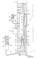
- the drawing shows a longitudinal section through the brake cylinder and barrel cylinder surrounding the gun barrel.
- the gun barrel 1 is the gun barrel, the rear end of which has the breech 2.
- the gun barrel 1 is guided axially displaceably in a cylindrical sleeve 3.
- the cylindrical sleeve 3 is rigidly connected via a connector 4 to the cradle 5, which carries the shield pins 6 for storage on the carriage, not shown.
- the working space of the brake cylinder is designated 8.
- the cylinder part 9 of the brake cylinder simultaneously forms the tube cradle 5.
- the piston part 7, which carries the piston 10, is rigidly connected to the closure 2. During recoil, the piston part 7 moves with the gun barrel 1 in the direction of the arrow 11, while the cylinder part 9 forming the tube cradle 5 is held on the mount.
- the hydraulic medium is displaced by the piston part 10 from the working space 8 of the brake cylinder and passes through a throttle gap 12 between the piston 10 and the inner wall 13 of the cylinder part of the brake cylinder to the other side of the piston 10 into a space 14
- the recoil has been braked.
- Part 7 forms the cylinder part 16 of the fore cylinder and part 3 forms the piston part 17 of the fore cylinder.
- 18 is an energy accumulator which has a piston 19 and a space 20 in which there is a spring or a gas cushion, indicated by 21.
- the space 22 of the energy accumulator 18 is connected via a line 23, a channel 24 and a channel 25 to the working space of the tube cylinder 15.
- the working space of the tube forestry cylinder 15 is delimited on the one hand by an outwardly projecting annular surface 26 of the part 3 or the piston part 17 and on the other hand by an inwardly projecting annular surface 27 of the cylinder part 16 of the tube forestry cylinder 15.
- the part 3 or the piston part 17 of the tube forestry cylinder is pressed into the position shown, since this pressure acts between the surfaces 26 and 27. In this way, the gun barrel 1 is brought back into the rest position shown after the launch.
- the piston part 7 of the brake cylinder On the side of the piston 10 facing the pipe mouth (on the left in the drawing), the piston part 7 of the brake cylinder has a rotating surface 32 which tapers conically in the direction of the pipe mouth. This rotation surface is immersed in an inwardly projecting ring rim 33 of the cylinder part 9, an annular gap 34 being left free between the rotation surface 32 and the ring rim 33. This annular gap 34 forms a throttle cross section, which becomes smaller and smaller towards the end of the forward movement of the gun barrel 1, as a result of which the forward movement is braked. Between this surface of rotation 32 and the piston 10, a number of bores 35 are provided which lead into the space 14. A ring 36 is freely displaceably mounted on the piston part 7.
- the piston 10 which is rigidly connected to the gun barrel 1, moves backwards in the direction of the arrow 11. Due to its inertia, the ring 36 remains behind and therefore releases the bores 35, so that a vacuum is created in the room 14 is avoided at the beginning of the recoil.
Landscapes
- Engineering & Computer Science (AREA)
- General Engineering & Computer Science (AREA)
- Toys (AREA)
- Braking Arrangements (AREA)
- Fluid-Damping Devices (AREA)
Applications Claiming Priority (2)
| Application Number | Priority Date | Filing Date | Title |
|---|---|---|---|
| AT1773/84 | 1984-05-29 | ||
| AT0177384A AT388451B (de) | 1984-05-29 | 1984-05-29 | Geschuetz |
Publications (2)
| Publication Number | Publication Date |
|---|---|
| EP0163626A1 EP0163626A1 (de) | 1985-12-04 |
| EP0163626B1 true EP0163626B1 (de) | 1988-11-30 |
Family
ID=3520688
Family Applications (1)
| Application Number | Title | Priority Date | Filing Date |
|---|---|---|---|
| EP85890120A Expired EP0163626B1 (de) | 1984-05-29 | 1985-05-28 | Geschütz |
Country Status (7)
| Country | Link |
|---|---|
| US (1) | US4656921A (es) |
| EP (1) | EP0163626B1 (es) |
| KR (1) | KR850008212A (es) |
| AT (1) | AT388451B (es) |
| BR (1) | BR8502518A (es) |
| DE (1) | DE3566574D1 (es) |
| ES (1) | ES8705625A1 (es) |
Families Citing this family (10)
| Publication number | Priority date | Publication date | Assignee | Title |
|---|---|---|---|---|
| US6619930B2 (en) | 2001-01-11 | 2003-09-16 | Mandus Group, Ltd. | Method and apparatus for pressurizing gas |
| KR100433030B1 (ko) * | 2001-07-02 | 2004-05-24 | 국방과학연구소 | 전차포용 주퇴복좌기 |
| US6578464B2 (en) * | 2001-08-29 | 2003-06-17 | Battelle Memorial Institute | Recoil mitigation device |
| US6745663B2 (en) * | 2001-08-29 | 2004-06-08 | Battelle Memorial Institute | Apparatus for mitigating recoil and method thereof |
| US6789456B2 (en) | 2001-08-29 | 2004-09-14 | Battelle Memorial Institute | Braking system |
| US6802406B2 (en) * | 2002-12-17 | 2004-10-12 | United Defense, L.P. | Recoil brake isolation system |
| DE102006003510A1 (de) * | 2006-01-24 | 2007-07-26 | Oerlikon Contraves Ag | Gasfeder für eine Revolver- oder Verschlusskanone |
| US7878105B2 (en) | 2007-04-02 | 2011-02-01 | Grinnell More | Mitigating recoil in a ballistic robot |
| US8161863B1 (en) * | 2010-12-13 | 2012-04-24 | The United States Of America As Represented By The Secretary Of The Army | Recoil-actuated gun scavenger |
| CN110360890B (zh) * | 2019-08-30 | 2022-05-17 | 中国人民解放军空军工程大学 | 一种具有抗后坐力的无人机机载射网装置 |
Family Cites Families (10)
| Publication number | Priority date | Publication date | Assignee | Title |
|---|---|---|---|---|
| DE55189C (de) * | MAXIM NORDENFELT GUNS AND AMMUNITION COMPANY LIMITED in Westminster, England, 32 Victoria Street | Flüssigkeits-Bremse mit Feder zum Regeln des Rück- und Vorlaufs von Geschützen | ||
| US415569A (en) * | 1889-11-19 | schneider | ||
| DE428976C (de) * | 1924-10-19 | 1926-05-18 | Rheinische Metallw & Maschf | Rohrruecklaufgeschuetz mit zwei Geschuetzrohren verschiedenen Kalibers |
| US2072099A (en) * | 1934-04-07 | 1937-03-02 | American Ordnance Corp | Ordnance |
| US2395488A (en) * | 1943-04-17 | 1946-02-26 | Victor F Lucht | Recoil mechanism |
| US2454818A (en) * | 1946-03-07 | 1948-11-30 | Victor F Lucht | Gun recoil spring surge dampener |
| US2442371A (en) * | 1946-03-18 | 1948-06-01 | Us Sec War | Gun recoil mechanism |
| US2715856A (en) * | 1951-05-11 | 1955-08-23 | Alexander E Kramer | Inclosed concentric recoil mechanism to facilitate replacement of gun tubes |
| US4038905A (en) * | 1976-04-29 | 1977-08-02 | The United States Of America As Represented By The Secretary Of The Army | Compressible fluid recoil system |
| US4296670A (en) * | 1979-06-29 | 1981-10-27 | General Electric Company | Ordnance recoil energy control and recovery system |
-
1984
- 1984-05-29 AT AT0177384A patent/AT388451B/de not_active IP Right Cessation
-
1985
- 1985-05-13 US US06/733,365 patent/US4656921A/en not_active Expired - Fee Related
- 1985-05-28 EP EP85890120A patent/EP0163626B1/de not_active Expired
- 1985-05-28 DE DE8585890120T patent/DE3566574D1/de not_active Expired
- 1985-05-28 BR BR8502518A patent/BR8502518A/pt not_active IP Right Cessation
- 1985-05-28 ES ES543546A patent/ES8705625A1/es not_active Expired
- 1985-05-28 KR KR1019850003657A patent/KR850008212A/ko not_active Application Discontinuation
Also Published As
| Publication number | Publication date |
|---|---|
| EP0163626A1 (de) | 1985-12-04 |
| DE3566574D1 (en) | 1989-01-05 |
| ES543546A0 (es) | 1987-05-01 |
| KR850008212A (ko) | 1985-12-13 |
| BR8502518A (pt) | 1986-01-28 |
| AT388451B (de) | 1989-06-26 |
| ES8705625A1 (es) | 1987-05-01 |
| ATA177384A (de) | 1988-11-15 |
| US4656921A (en) | 1987-04-14 |
Similar Documents
| Publication | Publication Date | Title |
|---|---|---|
| EP0163626B1 (de) | Geschütz | |
| DE102016009047B3 (de) | Rohrwaffe mit Rückstoßdämpfer | |
| DE3728533C2 (es) | ||
| DE623261C (de) | Selbsttaetige Feuerwaffe, insbesondere Maschinengewehr, nach dem Gasdruckladeprinziparbeitend | |
| EP3488172B1 (de) | Rohrwaffe, insbesondere pistole, mit rückstossdämpfer | |
| DE3015097C2 (de) | Hydropneumatische Vorrichtung zum Bremsen und Vorholen eines Geschützrohres | |
| EP0352584B1 (de) | Geschossansetzer für Artillerie | |
| DE2335649C2 (de) | Vorrichtung zum Entnehmen eines Teils der Rückstoßenergie für eine Waffenfunktion eines Geschützes | |
| DE1578372C3 (de) | Steuervorrichtung zur Entriegelung des Verschlusses einer Gasdrucklader-Feuerwaffe | |
| EP0027863B1 (de) | Hydraulische Rohrrücklaufbremse zum Abbremsen des Waffenrohres nach der Geschossdurchlaufzeit | |
| EP0220370B1 (de) | Rohrbremse | |
| DE2950218C2 (es) | ||
| DE3728532A1 (de) | Rohrbremse fuer eine rohrwaffe | |
| DE2751042A1 (de) | Gasbetaetigte vorrichtung zum laden eines geschosses in ein automatisches geschuetz | |
| DE1029710B (de) | Feuerwaffe, die bei jedem Schuss in ihrer Gesamtheit gegenueber einem Halter zuruecklaeuft | |
| DE102008062093B4 (de) | Geschützrückstoß | |
| DE4009050C2 (es) | ||
| DE3015102C2 (de) | Waffenvorlaufdämpfer für eine Maschinenkanone mit Keilverschluß | |
| EP0353398B1 (de) | Vorholsperrvorrichtung | |
| DE2655708C2 (de) | Vorrichtung zum Bestimmen des Anzündzeitpunkts einer schwimmend gelagerten Maschinenkanone | |
| AT388613B (de) | Einrichtung zur kompensation der hochschlagund rueckstossenergie von faustfeuerwaffen | |
| DE1019935B (de) | Ladevorrichtung fuer Waffen gepanzerter Fahrzeuge | |
| DE1728569C2 (de) | Automatische Feuerwaffe, insbesondere Schnellfeuerwaffe | |
| EP0627608B1 (de) | Automatischer Ansetzer für Artilleriegeschosse | |
| DE972758C (de) | Maschinengeschuetz oder Maschinengewehr |
Legal Events
| Date | Code | Title | Description |
|---|---|---|---|
| PUAI | Public reference made under article 153(3) epc to a published international application that has entered the european phase |
Free format text: ORIGINAL CODE: 0009012 |
|
| AK | Designated contracting states |
Designated state(s): BE CH DE FR GB IT LI LU NL SE |
|
| 17P | Request for examination filed |
Effective date: 19860318 |
|
| 17Q | First examination report despatched |
Effective date: 19870121 |
|
| ITF | It: translation for a ep patent filed |
Owner name: BARZANO' E ZANARDO MILANO S.P.A. |
|
| GRAA | (expected) grant |
Free format text: ORIGINAL CODE: 0009210 |
|
| AK | Designated contracting states |
Kind code of ref document: B1 Designated state(s): BE CH DE FR GB IT LI LU NL SE |
|
| GBT | Gb: translation of ep patent filed (gb section 77(6)(a)/1977) | ||
| REF | Corresponds to: |
Ref document number: 3566574 Country of ref document: DE Date of ref document: 19890105 |
|
| ET | Fr: translation filed | ||
| PG25 | Lapsed in a contracting state [announced via postgrant information from national office to epo] |
Ref country code: LU Free format text: LAPSE BECAUSE OF NON-PAYMENT OF DUE FEES Effective date: 19890531 |
|
| PLBE | No opposition filed within time limit |
Free format text: ORIGINAL CODE: 0009261 |
|
| STAA | Information on the status of an ep patent application or granted ep patent |
Free format text: STATUS: NO OPPOSITION FILED WITHIN TIME LIMIT |
|
| 26N | No opposition filed | ||
| PGFP | Annual fee paid to national office [announced via postgrant information from national office to epo] |
Ref country code: GB Payment date: 19900417 Year of fee payment: 6 Ref country code: CH Payment date: 19900417 Year of fee payment: 6 |
|
| PGFP | Annual fee paid to national office [announced via postgrant information from national office to epo] |
Ref country code: FR Payment date: 19900419 Year of fee payment: 6 |
|
| PGFP | Annual fee paid to national office [announced via postgrant information from national office to epo] |
Ref country code: DE Payment date: 19900427 Year of fee payment: 6 |
|
| PGFP | Annual fee paid to national office [announced via postgrant information from national office to epo] |
Ref country code: SE Payment date: 19900430 Year of fee payment: 6 Ref country code: LU Payment date: 19900430 Year of fee payment: 6 |
|
| PGFP | Annual fee paid to national office [announced via postgrant information from national office to epo] |
Ref country code: BE Payment date: 19900515 Year of fee payment: 6 |
|
| ITTA | It: last paid annual fee | ||
| PGFP | Annual fee paid to national office [announced via postgrant information from national office to epo] |
Ref country code: NL Payment date: 19900531 Year of fee payment: 6 |
|
| PG25 | Lapsed in a contracting state [announced via postgrant information from national office to epo] |
Ref country code: GB Effective date: 19910528 |
|
| PG25 | Lapsed in a contracting state [announced via postgrant information from national office to epo] |
Ref country code: SE Effective date: 19910529 |
|
| PG25 | Lapsed in a contracting state [announced via postgrant information from national office to epo] |
Ref country code: LI Effective date: 19910531 Ref country code: CH Effective date: 19910531 Ref country code: BE Effective date: 19910531 |
|
| BERE | Be: lapsed |
Owner name: VOEST-ALPINE A.G. Effective date: 19910531 |
|
| PG25 | Lapsed in a contracting state [announced via postgrant information from national office to epo] |
Ref country code: NL Effective date: 19911201 |
|
| NLV4 | Nl: lapsed or anulled due to non-payment of the annual fee | ||
| GBPC | Gb: european patent ceased through non-payment of renewal fee | ||
| PG25 | Lapsed in a contracting state [announced via postgrant information from national office to epo] |
Ref country code: FR Effective date: 19920131 |
|
| REG | Reference to a national code |
Ref country code: CH Ref legal event code: PL |
|
| PG25 | Lapsed in a contracting state [announced via postgrant information from national office to epo] |
Ref country code: DE Effective date: 19920303 |
|
| REG | Reference to a national code |
Ref country code: FR Ref legal event code: ST |
|
| EUG | Se: european patent has lapsed |
Ref document number: 85890120.0 Effective date: 19911209 |