EP0162290B1 - Stanzverfahren - Google Patents
Stanzverfahren Download PDFInfo
- Publication number
- EP0162290B1 EP0162290B1 EP85104682A EP85104682A EP0162290B1 EP 0162290 B1 EP0162290 B1 EP 0162290B1 EP 85104682 A EP85104682 A EP 85104682A EP 85104682 A EP85104682 A EP 85104682A EP 0162290 B1 EP0162290 B1 EP 0162290B1
- Authority
- EP
- European Patent Office
- Prior art keywords
- die
- punching
- driving
- hole
- die set
- Prior art date
- Legal status (The legal status is an assumption and is not a legal conclusion. Google has not performed a legal analysis and makes no representation as to the accuracy of the status listed.)
- Expired
Links
- 238000004080 punching Methods 0.000 title claims description 50
- 238000000034 method Methods 0.000 title claims description 20
- 238000003754 machining Methods 0.000 description 5
- 239000000758 substrate Substances 0.000 description 4
- 239000000919 ceramic Substances 0.000 description 3
- 230000008859 change Effects 0.000 description 3
- 238000002474 experimental method Methods 0.000 description 2
- 239000000463 material Substances 0.000 description 2
- 238000004904 shortening Methods 0.000 description 2
- 229910000838 Al alloy Inorganic materials 0.000 description 1
- 238000013459 approach Methods 0.000 description 1
- 239000011230 binding agent Substances 0.000 description 1
- 230000008878 coupling Effects 0.000 description 1
- 238000010168 coupling process Methods 0.000 description 1
- 238000005859 coupling reaction Methods 0.000 description 1
- 230000006866 deterioration Effects 0.000 description 1
- 230000000694 effects Effects 0.000 description 1
- 230000007246 mechanism Effects 0.000 description 1
- 230000004048 modification Effects 0.000 description 1
- 238000012986 modification Methods 0.000 description 1
- 239000004014 plasticizer Substances 0.000 description 1
- 230000004044 response Effects 0.000 description 1
Images
Classifications
-
- H—ELECTRICITY
- H05—ELECTRIC TECHNIQUES NOT OTHERWISE PROVIDED FOR
- H05K—PRINTED CIRCUITS; CASINGS OR CONSTRUCTIONAL DETAILS OF ELECTRIC APPARATUS; MANUFACTURE OF ASSEMBLAGES OF ELECTRICAL COMPONENTS
- H05K3/00—Apparatus or processes for manufacturing printed circuits
- H05K3/0011—Working of insulating substrates or insulating layers
- H05K3/0044—Mechanical working of the substrate, e.g. drilling or punching
- H05K3/005—Punching of holes
-
- B—PERFORMING OPERATIONS; TRANSPORTING
- B26—HAND CUTTING TOOLS; CUTTING; SEVERING
- B26F—PERFORATING; PUNCHING; CUTTING-OUT; STAMPING-OUT; SEVERING BY MEANS OTHER THAN CUTTING
- B26F1/00—Perforating; Punching; Cutting-out; Stamping-out; Apparatus therefor
- B26F1/38—Cutting-out; Stamping-out
-
- B—PERFORMING OPERATIONS; TRANSPORTING
- B26—HAND CUTTING TOOLS; CUTTING; SEVERING
- B26F—PERFORATING; PUNCHING; CUTTING-OUT; STAMPING-OUT; SEVERING BY MEANS OTHER THAN CUTTING
- B26F1/00—Perforating; Punching; Cutting-out; Stamping-out; Apparatus therefor
- B26F1/02—Perforating by punching, e.g. with relatively-reciprocating punch and bed
-
- B—PERFORMING OPERATIONS; TRANSPORTING
- B28—WORKING CEMENT, CLAY, OR STONE
- B28B—SHAPING CLAY OR OTHER CERAMIC COMPOSITIONS; SHAPING SLAG; SHAPING MIXTURES CONTAINING CEMENTITIOUS MATERIAL, e.g. PLASTER
- B28B11/00—Apparatus or processes for treating or working the shaped or preshaped articles
- B28B11/12—Apparatus or processes for treating or working the shaped or preshaped articles for removing parts of the articles by cutting
-
- B—PERFORMING OPERATIONS; TRANSPORTING
- B26—HAND CUTTING TOOLS; CUTTING; SEVERING
- B26F—PERFORATING; PUNCHING; CUTTING-OUT; STAMPING-OUT; SEVERING BY MEANS OTHER THAN CUTTING
- B26F2210/00—Perforating, punching, cutting-out, stamping-out, severing by means other than cutting of specific products
- B26F2210/08—Perforating, punching, cutting-out, stamping-out, severing by means other than cutting of specific products of ceramic green sheets, printed circuit boards and the like
-
- H—ELECTRICITY
- H05—ELECTRIC TECHNIQUES NOT OTHERWISE PROVIDED FOR
- H05K—PRINTED CIRCUITS; CASINGS OR CONSTRUCTIONAL DETAILS OF ELECTRIC APPARATUS; MANUFACTURE OF ASSEMBLAGES OF ELECTRICAL COMPONENTS
- H05K1/00—Printed circuits
- H05K1/02—Details
- H05K1/03—Use of materials for the substrate
- H05K1/0306—Inorganic insulating substrates, e.g. ceramic, glass
-
- H—ELECTRICITY
- H05—ELECTRIC TECHNIQUES NOT OTHERWISE PROVIDED FOR
- H05K—PRINTED CIRCUITS; CASINGS OR CONSTRUCTIONAL DETAILS OF ELECTRIC APPARATUS; MANUFACTURE OF ASSEMBLAGES OF ELECTRICAL COMPONENTS
- H05K2203/00—Indexing scheme relating to apparatus or processes for manufacturing printed circuits covered by H05K3/00
- H05K2203/01—Tools for processing; Objects used during processing
- H05K2203/0195—Tool for a process not provided for in H05K3/00, e.g. tool for handling objects using suction, for deforming objects, for applying local pressure
-
- H—ELECTRICITY
- H05—ELECTRIC TECHNIQUES NOT OTHERWISE PROVIDED FOR
- H05K—PRINTED CIRCUITS; CASINGS OR CONSTRUCTIONAL DETAILS OF ELECTRIC APPARATUS; MANUFACTURE OF ASSEMBLAGES OF ELECTRICAL COMPONENTS
- H05K3/00—Apparatus or processes for manufacturing printed circuits
- H05K3/0008—Apparatus or processes for manufacturing printed circuits for aligning or positioning of tools relative to the circuit board
-
- Y—GENERAL TAGGING OF NEW TECHNOLOGICAL DEVELOPMENTS; GENERAL TAGGING OF CROSS-SECTIONAL TECHNOLOGIES SPANNING OVER SEVERAL SECTIONS OF THE IPC; TECHNICAL SUBJECTS COVERED BY FORMER USPC CROSS-REFERENCE ART COLLECTIONS [XRACs] AND DIGESTS
- Y10—TECHNICAL SUBJECTS COVERED BY FORMER USPC
- Y10T—TECHNICAL SUBJECTS COVERED BY FORMER US CLASSIFICATION
- Y10T83/00—Cutting
- Y10T83/04—Processes
- Y10T83/0524—Plural cutting steps
- Y10T83/0572—Plural cutting steps effect progressive cut
-
- Y—GENERAL TAGGING OF NEW TECHNOLOGICAL DEVELOPMENTS; GENERAL TAGGING OF CROSS-SECTIONAL TECHNOLOGIES SPANNING OVER SEVERAL SECTIONS OF THE IPC; TECHNICAL SUBJECTS COVERED BY FORMER USPC CROSS-REFERENCE ART COLLECTIONS [XRACs] AND DIGESTS
- Y10—TECHNICAL SUBJECTS COVERED BY FORMER USPC
- Y10T—TECHNICAL SUBJECTS COVERED BY FORMER US CLASSIFICATION
- Y10T83/00—Cutting
- Y10T83/04—Processes
- Y10T83/0524—Plural cutting steps
- Y10T83/0577—Repetitive blanking
-
- Y—GENERAL TAGGING OF NEW TECHNOLOGICAL DEVELOPMENTS; GENERAL TAGGING OF CROSS-SECTIONAL TECHNOLOGIES SPANNING OVER SEVERAL SECTIONS OF THE IPC; TECHNICAL SUBJECTS COVERED BY FORMER USPC CROSS-REFERENCE ART COLLECTIONS [XRACs] AND DIGESTS
- Y10—TECHNICAL SUBJECTS COVERED BY FORMER USPC
- Y10T—TECHNICAL SUBJECTS COVERED BY FORMER US CLASSIFICATION
- Y10T83/00—Cutting
- Y10T83/162—With control means responsive to replaceable or selectable information program
- Y10T83/173—Arithmetically determined program
- Y10T83/175—With condition sensor
-
- Y—GENERAL TAGGING OF NEW TECHNOLOGICAL DEVELOPMENTS; GENERAL TAGGING OF CROSS-SECTIONAL TECHNOLOGIES SPANNING OVER SEVERAL SECTIONS OF THE IPC; TECHNICAL SUBJECTS COVERED BY FORMER USPC CROSS-REFERENCE ART COLLECTIONS [XRACs] AND DIGESTS
- Y10—TECHNICAL SUBJECTS COVERED BY FORMER USPC
- Y10T—TECHNICAL SUBJECTS COVERED BY FORMER US CLASSIFICATION
- Y10T83/00—Cutting
- Y10T83/202—With product handling means
- Y10T83/2074—Including means to divert one portion of product from another
- Y10T83/2079—Remaining or re-inserted product portion from base material
-
- Y—GENERAL TAGGING OF NEW TECHNOLOGICAL DEVELOPMENTS; GENERAL TAGGING OF CROSS-SECTIONAL TECHNOLOGIES SPANNING OVER SEVERAL SECTIONS OF THE IPC; TECHNICAL SUBJECTS COVERED BY FORMER USPC CROSS-REFERENCE ART COLLECTIONS [XRACs] AND DIGESTS
- Y10—TECHNICAL SUBJECTS COVERED BY FORMER USPC
- Y10T—TECHNICAL SUBJECTS COVERED BY FORMER US CLASSIFICATION
- Y10T83/00—Cutting
- Y10T83/444—Tool engages work during dwell of intermittent workfeed
- Y10T83/4604—Work feed functions as tool support
-
- Y—GENERAL TAGGING OF NEW TECHNOLOGICAL DEVELOPMENTS; GENERAL TAGGING OF CROSS-SECTIONAL TECHNOLOGIES SPANNING OVER SEVERAL SECTIONS OF THE IPC; TECHNICAL SUBJECTS COVERED BY FORMER USPC CROSS-REFERENCE ART COLLECTIONS [XRACs] AND DIGESTS
- Y10—TECHNICAL SUBJECTS COVERED BY FORMER USPC
- Y10T—TECHNICAL SUBJECTS COVERED BY FORMER US CLASSIFICATION
- Y10T83/00—Cutting
- Y10T83/647—With means to convey work relative to tool station
- Y10T83/654—With work-constraining means on work conveyor [i.e., "work-carrier"]
-
- Y—GENERAL TAGGING OF NEW TECHNOLOGICAL DEVELOPMENTS; GENERAL TAGGING OF CROSS-SECTIONAL TECHNOLOGIES SPANNING OVER SEVERAL SECTIONS OF THE IPC; TECHNICAL SUBJECTS COVERED BY FORMER USPC CROSS-REFERENCE ART COLLECTIONS [XRACs] AND DIGESTS
- Y10—TECHNICAL SUBJECTS COVERED BY FORMER USPC
- Y10T—TECHNICAL SUBJECTS COVERED BY FORMER US CLASSIFICATION
- Y10T83/00—Cutting
- Y10T83/869—Means to drive or to guide tool
- Y10T83/8742—Tool pair positionable as a unit
- Y10T83/8743—Straight line positioning
Definitions
- the present invention relates to a method of punching a substrate and, more particularly, to a punching method suitable for use in forming through holes in a workpiece of the kind referred to in the preamble portion of the patent claim, such a method is known from US-A-4,209,129.
- the punching is effected by an upper die set which is driven vertically up and down through an eccentric mechanism which converts a rotational motion of a motor into a vertical linear motion.
- the punching method disclosed in this document comprises the steps of setting a die to a home position in which said workpiece is disposed between un upper and a lower die sets forming said die, of driving a table-driving servomotor for said X-Y table system to move said workpiece to a predetermined position, of driving a die-driving servomotor for said die to move said die towards a punching position on said workpiece, of driving said die-driving servomotor to bring said upper die set close to said lower die set, of punching a through hole in said workpiece by said die, and of inversely driving said die-driving servomotor to displace said upper die set away from said workpiece.
- the object of the invention is to provide a punching method for forming through holes in a work which is mainly a ceramic green sheet, at a high efficiency and without suffering from clogging with chips.
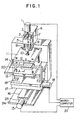
- a driving shaft of a servomotor 1 is coupled to a ball screw 2 by means of a coupling 3.
- the ball screw 2 engages with a nut 4 which is press-fitted to a slider 5.
- the slider 5 is movable linearly along parallel rods 8 and 9 born on a housing 7 which is fixed to a head 6, linearly along parallel rods 8 and 9 born on a housing 7 which is fixed to a head 6.
- the punching apparatus has a die including an upper die set 11.
- the die set 11 is connected to a free shank 10 fixed to the lower end of the slider 5.
- a punch (not shown) for punching a through hole in a green sheet 12 is embedded in the upper die set 11.
- the die also has a lower die set 13 which is fixed onto a bed 14.
- the punching apparatus further has X-Y tables consisting of a Y-table 16 and an X-table 19.
- the Y-table 16 is carried by a Y-table housing 25 which is fixed to a base 24, and is linearly moved by means of a servomotor 15.
- the Y-table 16 carries an X-table housing 17 which extends at a right angle to the Y-table 16.
- the X-table 19 is linearly moved on the X-table housing 17 by a servomotor 18.
- a support member 20 for supporting the green sheet 12 is fixed on the X-table 19.
- the X-table 19 is movable in a horizontal plane under the bed 14 by means of the servomotors 15 and 18. This in turn permits the top portion of the support member 20 to move in a horizontal plane between the upper and lower die sets 11 and 13, in accordance with the horizontal movement of the X-table 19.
- the servomotor 1 operates to drive the ball screw 2 upon receipt of a punching start signal from a microcomputer 21, so that the slider 5 moves linearly downwardly along the rods 8 and 9 to drive the upper die set 11 downwardly.
- the microcomputer 21 issues the commands to instantaneously stop and then reverse the servomotor 1 so as to raise the upper die set 11 to a predetermined level.
- either one or both servomotors 15 and 18 operate in accordance with commands from the microcomputer 21 to drive the X-table 19 so that the green sheet 12 on the support member 20 is moved to a position for the punching of the next through hole.
- the servomotor 1 operates in response to an operation command from the microcomputer 21 to move the upper die set 11 downwardly to punch the next through hole. This sequential operation is repeated in accordance with a program stored in the microcomputer, so that the required through holes are punched successively.
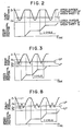
- Figure 2 is a time chart showing an example of the relationship between the position Z of the edge of the punch embedded in the upper die set 11 and the horizontal position of the green sheet 12.
- the top and lower stroke ends of the stroke of the punch edge are denoted by Z 1 and Z 4 , respectively.
- the upper die set 11 is positioned above the upper stroke end Z 1 of the punch edge, before the commencement of the punching operation and after the completion of the same.
- the punch edge Z is lowered from the upper stroke end Z 1 to the lower stroke end 24 to punch the through hole and is reversely moved upward to the upper stroke end Z 1 , and then either one or both X- and Y-tables are moved to relocate the green sheet 12.
- the position control along the Z-axis and the position control along the X- and/or Y-axis are conducted alternatingly.
- Figure 3 shows a time chart of operation which is specifically intended for shortening the time of the punching operation.
- a position Z 2 is to be set between the upper stroke end Z 1 and the position at which the upper die set 11 just leaves the green sheet 12 after the punching of the through hole.
- a position Z 3 is to be set between the lower stroke end Z 4 and the position at which the punch edge projects the lower face of the green sheet 12 after the punching of the through hole.
- an electric circuit when the punch edge approaches the lower stroke end Z 4 during the downward stroke of the upper die set 11, an electric circuit operates to automatically decelerate the punch, so that the velocity of downward movement of the punch when the punch edge reaches the lower stroke end Z 4 is as small as less than 1/10 that at the mid point between the stroke ends Z 1 and Z 4 .
- This controlling method effectively reduces the impact at a time of completion of the indexing but prolongs the indexing time undesirably.
- the microcomputer 21 issues a command to the servomotor 1 when the punch edge reaches the position Z 3 during downward stroke of the upper die set 11, such as to stop and reverse the servomotor 1 instantaneously thereby raising the upper die set 11 again.
- the time required for one cycle of punching operation is shortened because the time duration in which the upper die set 11 is lowered from the position Z 3 to the lower stroke end Z 4 and returned to the position Z 3 can be eliminated advantageously.
- the movement of the green sheet 12 for indexing can be commenced when the upper die set 11 reaches the position Z 2 during upward stroke of the upper die set 11. Accordingly the time which is required for the upper die set 11 to move from the position Z 2 to the position Z 1 can be used for indexing of the green sheet 12.
- the positions Z 2 and Z 3 may be set at any desired height within the range specified above.
- the stroke length i.e., the distance between the upper and lower stroke ends Z 1 and Z 2 is selected to be 4 mm
- the distance between the positions Z 1 and Z 2 and the distance between the positions Z 3 and Z 4 are selected to be 1 mm and 0.5 mm, respectively
- the controlling method shown in Figure 3 permits about 30% shortening of the punching time as compared with the case where the control is made in accordance with the controlling pattern shown in Figure 1.
- the punching method explained in connection with Figure 3 may be further modified in such a manner as to effect a duplication of punching in order to prevent any clogging of the punched through hole with the chip formed as a result of the punching.
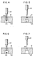
- FIGS 4 to 7 show enlarged sectional views of the green sheet 12, showing the manner in which the through hole is formed by a punch 22 which cooperates with a die 23.
- the die 23 is provided with a hole 23a of a diameter slightly greater than the diameter of the edge of the punch 22.
- the green sheet 12 is located while being held in contact with the upper face of the die 23.
- the green sheet 12 contains an organic binder and a plasticizer which generally exhibit tendency of sticking to the edge of the punch 22. It is, therefore, often experienced that the chip 12a, which is the material removed from the green sheet 12 as a result of the punching, sticks to the edge of the punch 22 due to strong punching pressure. The chip 12a, however, does not come off the punch 22 even after the edge of the punch 22 reaches the position Z 3 or Z 4 in Tigure 3 past the hole 23a formed in the die 23. In such a case, the chip 12a clogs in the through hole after the punch 22 is moved upward to the position Z 1 in Figure 2 or the position Z 2 in Figure 3, as shown in Figure 5.
- FIG. 8 is a time chart illustrating this operation. It will be seen that, as the punching operation is commenced, the edge of the punch embedded in the upper die set 11 is lowered from the position Z 1 to the position Z 3 via the position Z 2 and then raised towards the position Z 1 again. However, when the punch edge reaches the position Z 2 during its upward movement, the upper die set is lowered again to the position Z 3 so as to force out any chip 12a from the punched through hole.
- the punching method explained in connection with Figure 8 ensures safe removal of any chip staying in the punched through hole without requiring any substantial prolongation of the punching time.
- the second punching stroke for removing any chip staying in the punched through hole need not always be started at the position Z 2 but also from any other suitable position. It is also possible to modify the program such that the punch is driven two or more times through the punched through hole.
- the adaptability of the punching apparatus as a whole will be increased if the number of stroke cycles and the second punching can be set freely by manipulation of a switch on the control panel or through a change in the sequence program.
Landscapes
- Engineering & Computer Science (AREA)
- Mechanical Engineering (AREA)
- Forests & Forestry (AREA)
- Life Sciences & Earth Sciences (AREA)
- Microelectronics & Electronic Packaging (AREA)
- Manufacturing & Machinery (AREA)
- Ceramic Engineering (AREA)
- Chemical & Material Sciences (AREA)
- Structural Engineering (AREA)
- Perforating, Stamping-Out Or Severing By Means Other Than Cutting (AREA)
- Devices For Post-Treatments, Processing, Supply, Discharge, And Other Processes (AREA)
- Details Of Cutting Devices (AREA)
- Punching Or Piercing (AREA)
Claims (1)
- Stanzverfahren zur Herstellung wenigstens eines Durchgangslochs in einem Werkstück auf einem X-Y-Tischsystem, umfassend die Schritte: Einstellen eines Werkzeugs in eine Ruhestellung, in der das Werkstück zwischen einer oberen und einer unteren Werkzeughälfte, aus denen das Werkzeug besteht, angeordnet ist, Antreiben eines Tischantriebs-Servomotors, so daß das X-Y-Tischsystem das Werkstück in eine vorbestimmte Lage bewegt, Antreiben eines Werkzeugantriebs-Servomotors, so daß das Werkzeug in Richtung auf eine Stanzstellung auf dem Werkstück bewegt wird, Antreiben des Werkzeugantriebs-Servomotors, so daß die obere Werkzeughälfte nahe an die untere Werkzeughälfte gebracht wird, Stanzen eines Durchgangslochs in das Werkstück mittels des Werkzeugs, und umgekehrtes Antreiben des Werkzeugantriebs-Servomotors, um die obere Werkzeughälfte vom Werkstück wegzubewegen, dadurch gekennzeichnet, daß das Verfahren ferner folgende Schritte umfaßt:Anhalten der Umkehrbewegung des Werkzeugantriebs-Servomotors, bevor die obere Werkzeughälfte gehoben wird, um in die Ruhelage zurückzukehren;erneutes Antreiben des Werkzeugantriebs-Servomotors, um die obere Werkzeughälfte in das Stanzloch im Werkstück zu senken;Anhalten der Bewegung des Werkzeugantriebs-Servomotors, befor die obere'Werkzeughälfte in einem Hubende gesenkt wird; underneutes Antreiben des Werkzeugantriebs-Servomotors in Umkehrrichtung, um die obere Werkzeughälfte in die Ruhestellung zu heben.
Applications Claiming Priority (2)
| Application Number | Priority Date | Filing Date | Title |
|---|---|---|---|
| JP78445/84 | 1984-04-20 | ||
| JP59078445A JPS60228099A (ja) | 1984-04-20 | 1984-04-20 | 打抜き加工方法 |
Publications (2)
| Publication Number | Publication Date |
|---|---|
| EP0162290A1 EP0162290A1 (de) | 1985-11-27 |
| EP0162290B1 true EP0162290B1 (de) | 1989-01-11 |
Family
ID=13662237
Family Applications (1)
| Application Number | Title | Priority Date | Filing Date |
|---|---|---|---|
| EP85104682A Expired EP0162290B1 (de) | 1984-04-20 | 1985-04-18 | Stanzverfahren |
Country Status (5)
| Country | Link |
|---|---|
| US (1) | US4653365A (de) |
| EP (1) | EP0162290B1 (de) |
| JP (1) | JPS60228099A (de) |
| KR (1) | KR900002425B1 (de) |
| DE (1) | DE3567401D1 (de) |
Cited By (1)
| Publication number | Priority date | Publication date | Assignee | Title |
|---|---|---|---|---|
| SG136006A1 (en) * | 2006-03-27 | 2007-10-29 | Silvertown Machine Tools | Improved punch and die assembly |
Families Citing this family (29)
| Publication number | Priority date | Publication date | Assignee | Title |
|---|---|---|---|---|
| JPS6399199A (ja) * | 1986-12-26 | 1988-04-30 | 潮工業有限会社 | プレス加工装置 |
| JPH08398B2 (ja) * | 1987-04-24 | 1996-01-10 | 潮工業有限会社 | 薄板状物の穿孔装置及び穿孔装置用パンチングユニツト |
| US4990080A (en) * | 1988-06-29 | 1991-02-05 | Ushio Co. Ltd. | Punch press for piercing green sheet with liner |
| JPH0215294U (de) * | 1988-07-06 | 1990-01-30 | ||
| JPH02124295A (ja) * | 1988-10-28 | 1990-05-11 | Ushio Kk | 多軸穿孔装置 |
| EP0367185B1 (de) * | 1988-10-31 | 1994-07-06 | Ushio Co. Limited | Verfahren und Vorrichtung zum Gruppenlochen |
| ATE114262T1 (de) * | 1991-09-17 | 1994-12-15 | Siemens Nixdorf Inf Syst | Verfahren zum bohren von mehrlagenleiterplatten. |
| ES2103594T3 (es) * | 1993-05-15 | 1997-09-16 | Emrich Dirk | Dispositivo, herramienta de apriete y procedimiento para la separacion de restos de recortes en el troquelado de carton. |
| US5448933A (en) * | 1994-03-01 | 1995-09-12 | The Whitaker Corporation | Stamping machine stripper and die set |
| JP2705591B2 (ja) * | 1994-10-04 | 1998-01-28 | 村田機械株式会社 | パンチ駆動制御装置 |
| US5694804A (en) * | 1995-04-03 | 1997-12-09 | The Whitaker Corporation | Stamping and forming machine having high speed toggle actuated ram |
| US5692423A (en) * | 1995-05-09 | 1997-12-02 | Kabushiki Kaisha Fujikoshi | Vibration finishing method and apparatus for same |
| JP3392998B2 (ja) * | 1995-12-25 | 2003-03-31 | 日本碍子株式会社 | シート材の加工装置 |
| US5836226A (en) * | 1995-12-25 | 1998-11-17 | Ngk Insulators, Ltd. | Apparatus for progressively feeding and machining sheet material |
| US6314852B1 (en) * | 1998-08-03 | 2001-11-13 | International Business Machines Corporation | Gang punch tool assembly |
| US6199464B1 (en) | 1999-07-12 | 2001-03-13 | Lucent Technologies, Inc. | Method and apparatus for cutting a substrate |
| US6468453B1 (en) * | 1999-10-08 | 2002-10-22 | Shear Technologies, Llc | Methods and apparatus for manufacturing fiber-cement soffits with air vents |
| KR20020020464A (ko) * | 2000-09-08 | 2002-03-15 | 안영애 | 빛 투과용 홀가공 시트재의 성형방법 |
| JP2002346988A (ja) * | 2001-05-29 | 2002-12-04 | Yutaka Haitekku Kk | 高速cncパンチング装置 |
| JP3741995B2 (ja) * | 2001-10-31 | 2006-02-01 | 株式会社ルネサステクノロジ | 半導体装置の樹脂封止後におけるタイバーの除去装置及び方法、並びに半導体装置の製造方法 |
| JP2006088260A (ja) * | 2004-09-22 | 2006-04-06 | Sumitomo Metal Mining Package Materials Co Ltd | 接着剤層付きフレキシブル樹脂基板の穴開け加工方法 |
| WO2007000804A1 (ja) * | 2005-06-27 | 2007-01-04 | Beac Co., Ltd. | プリント配線基板の穿孔方法、プリント配線基板、boc用基板及び穿孔装置 |
| US20100192742A1 (en) * | 2009-01-30 | 2010-08-05 | Michigan Lasercut | Stripping apparatus |
| JP2012000727A (ja) * | 2010-06-17 | 2012-01-05 | Nissan Motor Co Ltd | ワーク切断装置及びワーク切断装置の切断刃清掃方法 |
| JP5186619B2 (ja) * | 2011-05-30 | 2013-04-17 | 武一 鈴木 | 抜き装置 |
| DE102013015180A1 (de) * | 2013-09-11 | 2015-03-12 | Webo Werkzeugbau Oberschwaben Gmbh | Verfahren und Vorrichtung zum Präzisionsschneiden von Werkstücken in einer Presse |
| CN108055778A (zh) * | 2017-11-21 | 2018-05-18 | 江门市浩远电子科技有限公司 | 一种柔性线路板加工用定位夹具 |
| CN112936432A (zh) * | 2021-02-25 | 2021-06-11 | 苏州汇富弘自动化科技有限公司 | 一种伺服冲床一体机 |
| CN114012918B (zh) * | 2022-01-05 | 2022-03-15 | 江苏明芯微电子股份有限公司 | 一种带有夹持结构的电子芯片的冲切工具 |
Family Cites Families (7)
| Publication number | Priority date | Publication date | Assignee | Title |
|---|---|---|---|---|
| US2866506A (en) * | 1954-10-25 | 1958-12-30 | Hughes Aircraft Co | Digital systems for the automatic control of machinery |
| US3370492A (en) * | 1965-04-02 | 1968-02-27 | Smithe Machine Co Inc F L | Die cutting presses |
| US4162641A (en) * | 1977-10-28 | 1979-07-31 | Potomac Applied Mechanics, Inc. | Automatic loading and unloading for numerically controlled turret punch |
| US4209129A (en) * | 1978-12-29 | 1980-06-24 | International Business Machines Corporation | Cooling manifold for multiple solenoid operated punching apparatus |
| JPS5629614U (de) * | 1979-08-14 | 1981-03-20 | ||
| JPS6040360B2 (ja) * | 1979-09-19 | 1985-09-10 | 株式会社日立製作所 | プリント基板用数値制御パンチプレス |
| US4523749A (en) * | 1983-03-02 | 1985-06-18 | W. A. Whitney Corp. | Hole forming machine with adjustable work clamps |
-
1984
- 1984-04-20 JP JP59078445A patent/JPS60228099A/ja active Granted
-
1985
- 1985-04-18 US US06/724,767 patent/US4653365A/en not_active Expired - Lifetime
- 1985-04-18 KR KR1019850002612A patent/KR900002425B1/ko not_active Expired
- 1985-04-18 EP EP85104682A patent/EP0162290B1/de not_active Expired
- 1985-04-18 DE DE8585104682T patent/DE3567401D1/de not_active Expired
Cited By (1)
| Publication number | Priority date | Publication date | Assignee | Title |
|---|---|---|---|---|
| SG136006A1 (en) * | 2006-03-27 | 2007-10-29 | Silvertown Machine Tools | Improved punch and die assembly |
Also Published As
| Publication number | Publication date |
|---|---|
| EP0162290A1 (de) | 1985-11-27 |
| DE3567401D1 (en) | 1989-02-16 |
| JPH0225760B2 (de) | 1990-06-05 |
| KR900002425B1 (ko) | 1990-04-14 |
| JPS60228099A (ja) | 1985-11-13 |
| KR850007363A (ko) | 1985-12-02 |
| US4653365A (en) | 1987-03-31 |
Similar Documents
| Publication | Publication Date | Title |
|---|---|---|
| US4653365A (en) | Method for punching ceramic green sheet | |
| EP0847682B1 (de) | Siebdruckverfahren und siebdruckvorrichtung | |
| US4771663A (en) | Multistroke punching method and apparatus therefor | |
| EP0781635B1 (de) | Vorrichtung zum Lochen von blattförmigen Materialien | |
| JPH11138226A (ja) | プレス装置 | |
| EP0847849B1 (de) | Presse zum Formen von hergestellten Gegenständen aus Ton | |
| GB2104822A (en) | A method of and an apparatus for controlling a machine tool | |
| JPH07132495A (ja) | 基板分割装置 | |
| US4513677A (en) | Method and device for safe operation of an automatic sewing machine | |
| CN114850804A (zh) | 一种模型加工设备及加工工艺 | |
| US5177843A (en) | Turret punch press | |
| JP3946564B2 (ja) | パンチプレスによる立ち上げ、立ち下げ加工方法およびその方法に使用するパンチ金型並びにダイ金型 | |
| JPS6359772B2 (de) | ||
| DE19510230A1 (de) | Transfervorrichtung für elektrische Bauelemente, insbesondere Chips | |
| JPS6040360B2 (ja) | プリント基板用数値制御パンチプレス | |
| JPH06246731A (ja) | 突起を有するセラミック板材の製造方法 | |
| CN212760701U (zh) | 一种模具顶料装置 | |
| JPH0611690Y2 (ja) | 穿孔機械 | |
| JP4105296B2 (ja) | 電子部品装着装置 | |
| JPS6381003A (ja) | スル−ホ−ル形成装置 | |
| JPH08309725A (ja) | 穴明け型の構造 | |
| JP2026065976A (ja) | 加工機 | |
| JP3316950B2 (ja) | パンチプレス機 | |
| JP2766892B2 (ja) | シートピアシング装置のパンチ装置 | |
| KR930008599Y1 (ko) | 스테플러 침 성형장치의 배출장치 |
Legal Events
| Date | Code | Title | Description |
|---|---|---|---|
| PUAI | Public reference made under article 153(3) epc to a published international application that has entered the european phase |
Free format text: ORIGINAL CODE: 0009012 |
|
| AK | Designated contracting states |
Designated state(s): DE FR GB |
|
| 17P | Request for examination filed |
Effective date: 19851129 |
|
| 17Q | First examination report despatched |
Effective date: 19870220 |
|
| GRAA | (expected) grant |
Free format text: ORIGINAL CODE: 0009210 |
|
| AK | Designated contracting states |
Kind code of ref document: B1 Designated state(s): DE FR GB |
|
| REF | Corresponds to: |
Ref document number: 3567401 Country of ref document: DE Date of ref document: 19890216 |
|
| ET | Fr: translation filed | ||
| PLBE | No opposition filed within time limit |
Free format text: ORIGINAL CODE: 0009261 |
|
| STAA | Information on the status of an ep patent application or granted ep patent |
Free format text: STATUS: NO OPPOSITION FILED WITHIN TIME LIMIT |
|
| 26N | No opposition filed | ||
| PGFP | Annual fee paid to national office [announced via postgrant information from national office to epo] |
Ref country code: LU Payment date: 19911111 Year of fee payment: 13 |
|
| EPTA | Lu: last paid annual fee | ||
| PGFP | Annual fee paid to national office [announced via postgrant information from national office to epo] |
Ref country code: FR Payment date: 19980216 Year of fee payment: 14 |
|
| PGFP | Annual fee paid to national office [announced via postgrant information from national office to epo] |
Ref country code: GB Payment date: 19980408 Year of fee payment: 14 |
|
| PGFP | Annual fee paid to national office [announced via postgrant information from national office to epo] |
Ref country code: DE Payment date: 19980629 Year of fee payment: 14 |
|
| PG25 | Lapsed in a contracting state [announced via postgrant information from national office to epo] |
Ref country code: GB Free format text: LAPSE BECAUSE OF NON-PAYMENT OF DUE FEES Effective date: 19990418 |
|
| GBPC | Gb: european patent ceased through non-payment of renewal fee |
Effective date: 19990418 |
|
| PG25 | Lapsed in a contracting state [announced via postgrant information from national office to epo] |
Ref country code: FR Free format text: LAPSE BECAUSE OF NON-PAYMENT OF DUE FEES Effective date: 19991231 |
|
| REG | Reference to a national code |
Ref country code: FR Ref legal event code: ST |
|
| PG25 | Lapsed in a contracting state [announced via postgrant information from national office to epo] |
Ref country code: DE Free format text: LAPSE BECAUSE OF NON-PAYMENT OF DUE FEES Effective date: 20000201 |