EP0150653B2 - Beschlag für einen sich in zwei Richtungen öffnenden Flügel, welcher eine Sperrvorrichtung für eine der Öffnungsrichtungen aufweist - Google Patents
Beschlag für einen sich in zwei Richtungen öffnenden Flügel, welcher eine Sperrvorrichtung für eine der Öffnungsrichtungen aufweist Download PDFInfo
- Publication number
- EP0150653B2 EP0150653B2 EP84440069A EP84440069A EP0150653B2 EP 0150653 B2 EP0150653 B2 EP 0150653B2 EP 84440069 A EP84440069 A EP 84440069A EP 84440069 A EP84440069 A EP 84440069A EP 0150653 B2 EP0150653 B2 EP 0150653B2
- Authority
- EP
- European Patent Office
- Prior art keywords
- locking
- fitting
- fitting according
- locking member
- opening
- Prior art date
- Legal status (The legal status is an assumption and is not a legal conclusion. Google has not performed a legal analysis and makes no representation as to the accuracy of the status listed.)
- Expired - Lifetime
Links
Images

Classifications
-
- E—FIXED CONSTRUCTIONS
- E05—LOCKS; KEYS; WINDOW OR DOOR FITTINGS; SAFES
- E05D—HINGES OR SUSPENSION DEVICES FOR DOORS, WINDOWS OR WINGS
- E05D15/00—Suspension arrangements for wings
- E05D15/48—Suspension arrangements for wings allowing alternative movements
- E05D15/52—Suspension arrangements for wings allowing alternative movements for opening about a vertical as well as a horizontal axis
- E05D15/526—Safety devices
-
- E—FIXED CONSTRUCTIONS
- E05—LOCKS; KEYS; WINDOW OR DOOR FITTINGS; SAFES
- E05D—HINGES OR SUSPENSION DEVICES FOR DOORS, WINDOWS OR WINGS
- E05D15/00—Suspension arrangements for wings
- E05D15/48—Suspension arrangements for wings allowing alternative movements
- E05D15/52—Suspension arrangements for wings allowing alternative movements for opening about a vertical as well as a horizontal axis
-
- E—FIXED CONSTRUCTIONS
- E05—LOCKS; KEYS; WINDOW OR DOOR FITTINGS; SAFES
- E05Y—INDEXING SCHEME ASSOCIATED WITH SUBCLASSES E05D AND E05F, RELATING TO CONSTRUCTION ELEMENTS, ELECTRIC CONTROL, POWER SUPPLY, POWER SIGNAL OR TRANSMISSION, USER INTERFACES, MOUNTING OR COUPLING, DETAILS, ACCESSORIES, AUXILIARY OPERATIONS NOT OTHERWISE PROVIDED FOR, APPLICATION THEREOF
- E05Y2900/00—Application of doors, windows, wings or fittings thereof
- E05Y2900/10—Application of doors, windows, wings or fittings thereof for buildings or parts thereof
- E05Y2900/13—Type of wing
- E05Y2900/148—Windows
Definitions
- the invention relates to a window fitting or French window maneuverable by a single handle making it possible to give the fitting a locking position and two "French” and “bellows” opening positions, this fitting, placed between the sleeping frame and the opening frame being provided with at least one locking point formed by a locking element secured to an operating rod, sliding in a groove formed in the edge of one of the frames and subjected to a displacement d '' a step to bring the fitting from the locking position to one of the two opening positions, followed by a movement of one step to bring the fitting from the first opening position to the second opening position via the handle and a keeper cooperating with the locking element and arranged on the other frame, a safety device locking the locking element of the window is in a position of v fitting of the fitting, either in a "French” open position, this latter position being reached after a displacement of a length of one step made by the linear translation of the locking point using a control element.
- the single handle actuates an operating rod provided with at least one locking element. Any change in position of a quarter turn of the handle causes the displacement of the operating rod for a given stroke, the term used in the present description being "one step".
- This handle, operating rod and locking element assembly is integral with one of the frames but, preferably, with the opening frame. The locking element cooperates with a keeper secured to the other frame.
- tilt-and-turn windows or French windows When tilt-and-turn windows or French windows are installed in public premises such as school, hospital and others, they are subject to certain safety rules and in particular these windows or French windows must be provided with a device preventing the opening "à laicy" of the opening frame, this as security against any fall of people and / or objects through the window.
- the window or French window with a fitting according to the invention is given a certain security, in particular against any fall of people or objects through the window or French window.
- the tilt-and-turn window or French window keeps its locking position of the "French-style" opening of the opening frame .
- the user must not be misled because the risk of people or objects falling through the window or French window would be increased if, for one reason or another, this conviction would have been deleted and that the window or French window would again have two directions of opening of the opening frame.
- the strike Due to the vertical access to the adjustment screw, the strike can only be applied. Furthermore, because the slider moves vertically, the sole necessarily has an overall length greater than the normal length of a keeper. Thus, if one wants to replace a normal strike with a strike according to this prior document, it is necessary to modify the locations for fixing the strike and therefore, a new machining of the sleeping frame must be provided. In addition, to change the position of the strike by one step, the screw must have a relatively large number of turns. This results in a loss of time all the more important if it is a question of settling numerous waste in public premises such that school, hospital and others.
- the object of the present invention is to remedy these drawbacks.
- the invention as characterized in the claims, solves the problem of creating a window fitting or French window maneuverable by a single handle making it possible to give the fitting a locking position and two opening positions " à la negligence "et” à soufflet ", this fitting, placed between the sleeping frame and the opening frame being provided with at least one locking point formed by a first element, called locking element, integral with an operating rod , sliding in a groove formed in the edge of one of the frames and subjected to a displacement of one step to bring the fitting from the locking position to one of the two open positions, followed by a displacement d '' a step to bring the fitting from the first open position to the second open position via the handle and by a keeper constituting the second element of the locking point and coop ant with the locking element, while being placed on the other frame, a safety device locking one of the two elements of the window locking point either in a position for locking the fitting, or in a position opening "à lanosti", this
- the advantages obtained thanks to this invention consist essentially in that it allows, on the one hand, to transform the already existing fittings and put in place to bring them into compliance with safety rules and, on the other hand, to limit the manufacture of the fitting in a single series which can be used as normal fitting and / or as fitting blocking one of the openings of the opening frame.
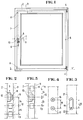
- the fitting 1 is disposed between the dormant frame 2 and the opening frame 3.
- the latter can open “à larely” by pivoting about a vertical articulation axis 4-4 ′ or “at bellows "by pivoting around a horizontal axis of articulation 5-5 '.
- This fitting 1 is operable by a single handle 6 actuating an operating rod 7 comprising at least one locking element 8 constituting one of the parts of a locking point 9.
- This locking element 8 cooperates with a keeper 10 constituting the other part of the locking point 9 to give the opening frame 3 either a locked position, or a position condemning the "French” opening, or a position allowing the opening "bellows”.
- the operating rod 7 By actuating the single handle 6, the operating rod 7 is given a linear displacement the stroke of which breaks down into two steps, the first step bringing the locking element 8 back to the locking point 9 from the locking position of the opening frame 3 at the position of the "French” opening of the same opening frame 3 and the second step brings the locking element 8 to the position of the "bellows” opening of the opening frame 3.
- the handle single 6, the operating rod 7 and the locking element 8 are secured to the opening frame 3 and the keeper 10 is secured to the fixed frame 2. Because, without modifying the spirit of the invention, the keeper 10 could be secured of the opening frame 3 and the single handle 6, the operating rod 7 and the locking element 8 could be arranged on the standing frame 2.
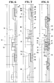
- the locking point 9 is moved by a distance corresponding to the pitch of the operating rod 7 , that is to say that one proceeds to a displacement of the locking element 8.
- the cooperation between the two parts 8, 10 of the locking point 9 is maintained, that is to say say that the striker 10 opposes the transverse movement of the locking element I-lage 8.
- the locking point 9 consists of the locking element 8 disposed on the opening frame 3 and the keeper 10 secured to the standing frame 2.
- the mark 11 represents the locking position of the opening frame 3
- the mark 12 represents the position opening "à lalie” of the opening frame 3
- the reference 13 represents the “bellows” opening position of the same opening frame 3
- the pitch between the locking position and the opening position "à lalie” being indicated by the reference 14 and the pitch located between the" French “opening position and the” bellows "opening position being indicated by the reference 15.
- the locking point 9 is in the locking position 11 of the opening frame 3 and there is cooperation between the locking element 8 and the keeper 10, so the opening frame 3 is in the position locking. If this cooperation is interrupted, that is to say when the locking element 8 is moved from step 14 and is at mark 12, the fitting allows the opening "à latress” of the opening frame 3 and s' it is located at reference 13, the fitting allows the opening "with bellows” of this same opening frame 3. For this purpose, the element of lock 8 will have taken step 15.
- the transposition is carried out by providing two fixing housings 16, 17 either in the operating rod 7 for the transposition of the locking element 8, or in the sleeping frame for the transposition of the keeper 10.
- the gap 18 between these two housings 16, 17 corresponds to step 14 or 15.
- the transposition of the locking element 8 is obtained by a linear translation.
- an elongated hole 19 is provided and the distance 20 between the two extreme positions 21, 22 corresponds to step 14 or 15.
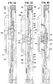
- the fitting comprises, in accordance with the invention, at least one locking point 9.
- This consists of a keeper 10 cooperating with a locking element 8.
- the keeper 10 is integral with the edge 25 of a metal frame capable of be the sleeping frame 2 of the tilt-and-turn window or French window, said keeper 10 projecting relative to the edge 25.
- the locking element 8 is integral with an intermediate operating rod 7 interposed between two sections of rod operation 26 and 27 actuated by the handle (not shown). This intermediate operating rod 7 and the operating rod sections 26 and 27 slide in a groove 28 produced in the edge 29 of the opening frame 3 of the window or French window.
- the latter comprises, on the one hand, at its lower end 30 an orifice 31 in which is engaged a stud 32 projecting by relative to the rear face 33 of a recess 34 produced at the upper end 35 of the operating rod section 27 and, on the other hand, at its upper end 36 a stud 37 protruding from the rear face 38 d 'a step 39 produced in said upper end 36.
- This stud 37 engages in an orifice 40 formed in the lower end 41 of the section of operating rod 26.
- the intermediate operating rod 7 has in its rear face 42 a longitudinal groove 43 serving as guide and housing for a slide 44.
- the latter is integral with the locking element 8.
- This locking element 8 passes through a longitudinal light 45 whose longitudinal axis 46 is located in the same plane as the longitudinal axis 47 of the intermediate operating rod 7.
- two holes 48, 49 are made, the center distance 50 of which corresponds to the movement of a step 14, 15 of the operating rod 7, 26, 27 actuated by said handle.
- These holes 48, 49 have approximately a circular shape whose diameter 51 is greater than the width 52 of the longitudinal slot 45.
- Each circle segment 53, 54, 55, 56 of these holes 48, 49 has a stop 57, 58 , 59, 60 diametrically opposite.
- These stops 57, 58, 59, 60 have a wall 61, 62, 63, 64 parallel to the transverse axis 65, 66 of the holes 48, 49.
- a safety device formed essentially by a safety bolt 69.
- the safety bolt 69 is free to rotate relative to the element locking 8 but integral in translation with the latter via the slide 44.
- This safety bolt 69 has in the front face 70 of a body 71 a groove 72.
- This body 71 has a flat 73 whose ends 74, 75 are rounded and move concentrically with respect to the circular segments 53, 54, 55, 56 of the holes 48, 49. The diameter of these rounded ends 74, 75 corresponds to the diameter 51 of the holes 48, 49.
- the width 76 of the flat 73 corresponds to the width 52 of the longitudinal slot 45 produced in the intermediate operating rod 7, which allows the translation of the safety bolt 69 and, consequently, of the locking element 8.
- the two faces 77, 78 of this flat 73 abut against the walls 61, 62, 63, 64 of the stops 57, 58 or 59, 60 of the holes 48, 49.
- the rotation of the safety bolt 69 is limited and it is certain that the flat 73 is perpendicular to the longitudinal axis 46 of the longitudinal lumen 47.
- a slot 80 is made in the front face 79 of the locking element 8 identical to the groove 72 of the safety bolt 69. Furthermore, a hole 81 is made in the slot 80 of which the diameter is greater than the width 82 of the slot 80 but less than the length 83 of the latter.
- This control element 84 has an approximate shape of a key. By means of this control element 84, it is possible to transform the locked position of the safety bolt 69 into the unlocked position or vice versa for the translation of the locking element 8.
- the width 85 of this control element 84 corresponds to the length 83 of the slot 80 while its thickness is a function of the width 82 of this same slot 80.
- the height 89 of this constriction 87 is slightly greater than the thickness 90 situated between the housing 68 and the front face 79 of the locking element 8.
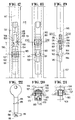
- the fitting shown in these figures is designed to be adapted to a tilt-and-turn window or French window made of wood and / or plastic. It comprises at least one locking point 109. This is composed of a keeper 110 housed in a notch 191 produced in the edge 25 of a sleeping frame 102 and of a locking element 108 secured to a rod intermediate maneuver 107 connecting together two sections of operating rod 126, 127 actuated by the single handle (the upper rod section 126 and the handle are not shown). All of these operating rods 107, 126, 127 slides in a groove 128 produced in the edge 129 of the opening frame 103 of the window or French window. In this same song 129, a second groove 192 of wider width than that of the groove 128 is practiced.
- this second groove 192 is housed a headrest 193 held at a distance from the bottom 194 of the groove 128 by studs of thickness 195.
- the connection between the intermediate operating rod 107 and the two sections of operating rod 126, 127 can be identical to that described above but can also be done by connecting sleeves 196 integral with a recess 134 formed at the ends 135 maneuvering rod sections 126, 127.
- These connecting sleeves 196 have a "U" shaped section.
- the internal faces of the wings of these connecting sleeves 196 have a toothing 197 meshing with a toothing 198 produced at the ends 130 of the intermediate operating rod 107.
- the latter comprises at the locations of the studs of thickness 195 with slots 199 for their passage.
- the headrest 193 also has a slot 200 at the location of the locking point 109 for the passage of the locking element 108.
- a slide 144 made integral with the locking element 108.
- a longitudinal slot 145 is formed in the intermediate maneuvering rod 107 in which two holes 148, 149 are made, the center distance 150 of which corresponds to the movement of a step of all the rods 107, 126, 127. The diameter 151 of these holes 148, 149 is greater than the width 152 of the longitudinal slot 145.
- Each hole 148, 149 has diametrically opposed stops 157, 158 and 159, 160 whose wall 161, 162, 163, 164 is parallel to the axes 165, 166 perpendicular to the axis 146 of the longitudinal light 145.
- These stops 157, 158, 159, 160 serve as stops on the two faces 177, 178 d 'A flat 173 of a safety bolt 169.
- the latter is disposed in a housing 168 made in the rear face 167 of the locking element 108.
- the safety bolt 169 has in its front face 170 a groove 172, the l the longitudinal axis is perpendicular to the longitudinal axis of the flat 173.
- This groove 172 faces a slot 180 produced in the front face 179 of the locking element 108. This slot 180 allows the end 86 of the control element 84.
- the rounded ends 74,174 and 75,175 slide along the circular segments 53,153; 54,154 from drilling 48,148 until the faces 77, 177; 78, 178 of the flat 73, 173 abut against the stops 57, 157 and 58, 158 of the bore 48, 148 of the longitudinal slot 45, 145 produced in the intermediate operating rod 7, 107. Therefore, the safety bolt 69,169 is in the locked position. It is only after this rotation that it becomes possible to remove the control element 84. Therefore, it is certain that the locking element 8,108 is in the correct position and it is impossible to change this position without be in possession of the control element 84.
Landscapes
- Engineering & Computer Science (AREA)
- Mechanical Engineering (AREA)
- Wing Frames And Configurations (AREA)
- Mutual Connection Of Rods And Tubes (AREA)
- Lock And Its Accessories (AREA)
Claims (15)
Priority Applications (1)
| Application Number | Priority Date | Filing Date | Title |
|---|---|---|---|
| AT84440069T ATE25124T1 (de) | 1984-01-25 | 1984-12-11 | Beschlag fuer einen sich in zwei richtungen oeffnenden fluegel, welcher eine sperrvorrichtung fuer eine der oeffnungsrichtungen aufweist. |
Applications Claiming Priority (4)
| Application Number | Priority Date | Filing Date | Title |
|---|---|---|---|
| FR8401238 | 1984-01-25 | ||
| FR8401238A FR2558513B1 (fr) | 1984-01-25 | 1984-01-25 | Ferrure pour ouvrant a deux sens d'ouverture presentant des moyens de blocage de l'un des sens d'ouverture |
| FR8401586A FR2558887B2 (fr) | 1984-01-31 | 1984-01-31 | Ferrure pour ouvrant a deux sens d'ouverture presentant des moyens de blocage de l'un des sens d'ouverture |
| FR8401586 | 1984-01-31 |
Publications (4)
| Publication Number | Publication Date |
|---|---|
| EP0150653A2 EP0150653A2 (de) | 1985-08-07 |
| EP0150653A3 EP0150653A3 (en) | 1985-08-21 |
| EP0150653B1 EP0150653B1 (de) | 1987-01-21 |
| EP0150653B2 true EP0150653B2 (de) | 1994-07-06 |
Family
ID=26223787
Family Applications (1)
| Application Number | Title | Priority Date | Filing Date |
|---|---|---|---|
| EP84440069A Expired - Lifetime EP0150653B2 (de) | 1984-01-25 | 1984-12-11 | Beschlag für einen sich in zwei Richtungen öffnenden Flügel, welcher eine Sperrvorrichtung für eine der Öffnungsrichtungen aufweist |
Country Status (4)
| Country | Link |
|---|---|
| US (1) | US4624075A (de) |
| EP (1) | EP0150653B2 (de) |
| CA (1) | CA1267923A (de) |
| DE (1) | DE3462168D1 (de) |
Families Citing this family (12)
| Publication number | Priority date | Publication date | Assignee | Title |
|---|---|---|---|---|
| GB2175631B (en) * | 1985-05-24 | 1988-07-13 | Hardware & Systems Patents Ltd | Window |
| DE3710056C3 (de) * | 1987-03-27 | 1997-10-09 | Siegenia Frank Kg | Flügelrahmen für ein Fenster oder eine Tür, der aus Metall- oder Kunststoffprofilen zusammengesetzt ist |
| DE8810634U1 (de) * | 1988-08-23 | 1988-11-24 | August Bilstein GmbH & Co KG, 5828 Ennepetal | Dreh- oder Drehkippfenster oder -Tür |
| IT1235293B (it) * | 1989-06-01 | 1992-06-26 | Otlav Spa | Dispositivo per l'apertura ad anta e a ribalta di una finestra o di una porta finestra. |
| FR2756863B1 (fr) * | 1996-12-06 | 1999-01-22 | Ferco Int Usine Ferrures | Dispositif de securite de type antifausse manoeuvre pour une ferrure de verrouillage d'un vantail |
| US5881498A (en) * | 1997-09-27 | 1999-03-16 | Thermo-Roll Window Corp. | Tilt and turn window lock system |
| US6421960B1 (en) | 2000-03-16 | 2002-07-23 | Francis Manzella | Safety-lock for multi-position tilt and turn window |
| US6782661B2 (en) * | 2001-03-12 | 2004-08-31 | Francis Manzella | Mechanical actuator for a multi-position window |
| ATE375426T1 (de) * | 2002-10-01 | 2007-10-15 | Somfy Sas | Beschlagmechanik für ein drehkippfenster oder eine drehkipptüre |
| ITTO20060434A1 (it) * | 2006-06-15 | 2007-12-16 | Savio Spa | "gruppo di azionamento per serramenti" |
| IT1393807B1 (it) * | 2008-10-30 | 2012-05-11 | Gsg Int Spa | Dispositivo di chiusura per infissi. |
| CN102086742B (zh) * | 2009-12-02 | 2015-04-01 | 广东坚朗五金制品股份有限公司 | 平开、下悬双开式双扇窗及其窗构件、双开控制装置 |
Family Cites Families (5)
| Publication number | Priority date | Publication date | Assignee | Title |
|---|---|---|---|---|
| DE2429110A1 (de) * | 1974-06-18 | 1976-01-08 | Horst Korbi | Fenster mit dreh-kipp-beschlag |
| DE2434120C2 (de) * | 1974-07-16 | 1983-10-20 | Wilh. Frank Gmbh, 7022 Leinfelden-Echterdingen | Drehsicherungsvorrichtung an einem für Fenster, Türen od.dgl. mit wahlweise um zwei Achsen bewegbaren Flügeln, insbesondere Dreh-Kippfenstern, bestimmten Treibstangenbeschlag |
| DE2600307A1 (de) * | 1976-01-07 | 1977-07-21 | Ver Baubeschlag Gretsch Co | Fehlbedienungssperre fuer bedienungsgestaenge |
| DE2920581C3 (de) * | 1979-05-21 | 1987-03-26 | Siegenia-Frank Kg, 5900 Siegen | Zusatzverriegelung, insbesondere Mittelverriegelung, für Fenster, Türen od.dgl. |
| DE3307209C3 (de) * | 1983-03-01 | 1993-09-30 | Winkhaus Fa August | Fehlbedienungssicherungseinheit an einer Stulpschienen-Treibstangenbaueinheit eines Mehrfunktionenbeschlags, insbesondere eines Drehkippbeschlags |
-
1984
- 1984-12-11 EP EP84440069A patent/EP0150653B2/de not_active Expired - Lifetime
- 1984-12-11 DE DE8484440069T patent/DE3462168D1/de not_active Expired
- 1984-12-27 CA CA000471042A patent/CA1267923A/fr not_active Expired - Fee Related
-
1985
- 1985-01-10 US US06/690,465 patent/US4624075A/en not_active Expired - Fee Related
Also Published As
| Publication number | Publication date |
|---|---|
| EP0150653A2 (de) | 1985-08-07 |
| CA1267923A (fr) | 1990-04-17 |
| EP0150653B1 (de) | 1987-01-21 |
| DE3462168D1 (en) | 1987-02-26 |
| US4624075A (en) | 1986-11-25 |
| EP0150653A3 (en) | 1985-08-21 |
Similar Documents
| Publication | Publication Date | Title |
|---|---|---|
| EP0963498B1 (de) | Verschlussvorrichtung für eine tür | |
| EP0150653B2 (de) | Beschlag für einen sich in zwei Richtungen öffnenden Flügel, welcher eine Sperrvorrichtung für eine der Öffnungsrichtungen aufweist | |
| EP0044264A1 (de) | Verschluss für Schiebefenster, -tür, o.dgl. | |
| EP0924373B1 (de) | Treibstangenschloss für eine Tür, Fenstertür oder dergleichen | |
| FR2576628A1 (fr) | Fermeture de porte comprenant une serrure avec verrou et cremaillere et un element de verrouillage de securite relie a la serrure. | |
| EP0274975B1 (de) | Sicherheitsbeschlag für Tür oder Fenster mit Mitteln zum Verriegeln des Vierkantstiftes | |
| EP0801193B1 (de) | Einsteckschloss | |
| FR2632340A1 (fr) | Serrure a surete rapportee, munie d'une gorge incrochetable | |
| EP0438008B1 (de) | Treibstangenschloss für Tür, Fenster o. dgl. | |
| EP0229582A1 (de) | Treibstangenbeschlag mit Stulpschiene und zwei in entgegengesetzten Richtungen bewegte Treibstangen | |
| EP0606196B1 (de) | Schliessvorrichtung | |
| EP1059409B1 (de) | Antriebsgetriebe für Schlossnuss | |
| EP0220127A1 (de) | Verriegelungseinrichtung für Schiebeflügel | |
| EP0285534B1 (de) | Griff für einen Treibstangenbeschlag für Türen, Fenster oder dergleichen | |
| FR2680825A1 (fr) | Ferrure de verrouillage pour porte, fenetre ou analogue. | |
| FR2583452A1 (fr) | Boitier de cremone a plaquer avec condamnation. | |
| CA1268500A (fr) | Ferrure de verrouillage, notamment pour ouvrant coulissant | |
| EP0997598B1 (de) | Schraubenführungsvorrichtung für Treibstange oder Treibstangenschloss | |
| FR2467277A1 (fr) | Verrou a entailler | |
| EP0310533B1 (de) | Elektrische Verriegelungsvorrichtung für Beschläge wie Treibstangen oder Treibstangenschlösser | |
| EP1842996A1 (de) | Basküle- oder Treibstangenbeschlag, der in einer Rahmenfalz eingespannt werden kann und mindestens eine Nuss umfasst | |
| EP0200663B1 (de) | Sicherheitsvorrichtung für Fenster, die sich in selektiver Weise um eine horizontale oder vertikale Achse öffnen | |
| FR2558887A2 (fr) | Ferrure pour ouvrant a deux sens d'ouverture presentant des moyens de blocage de l'un des sens d'ouverture | |
| EP1132558B1 (de) | Treibstangenschloss für eine Stalltür | |
| EP0123819A1 (de) | Treibstangenschloss für Fenster, Tür, o. dgl. |
Legal Events
| Date | Code | Title | Description |
|---|---|---|---|
| PUAI | Public reference made under article 153(3) epc to a published international application that has entered the european phase |
Free format text: ORIGINAL CODE: 0009012 |
|
| PUAL | Search report despatched |
Free format text: ORIGINAL CODE: 0009013 |
|
| AK | Designated contracting states |
Designated state(s): AT BE CH DE GB IT LI NL |
|
| AK | Designated contracting states |
Designated state(s): AT BE CH DE GB IT LI NL |
|
| 17P | Request for examination filed |
Effective date: 19850920 |
|
| 17Q | First examination report despatched |
Effective date: 19860410 |
|
| GRAA | (expected) grant |
Free format text: ORIGINAL CODE: 0009210 |
|
| ITF | It: translation for a ep patent filed | ||
| AK | Designated contracting states |
Kind code of ref document: B1 Designated state(s): AT BE CH DE GB IT LI NL |
|
| REF | Corresponds to: |
Ref document number: 25124 Country of ref document: AT Date of ref document: 19870215 Kind code of ref document: T |
|
| REF | Corresponds to: |
Ref document number: 3462168 Country of ref document: DE Date of ref document: 19870226 |
|
| PLBI | Opposition filed |
Free format text: ORIGINAL CODE: 0009260 |
|
| 26 | Opposition filed |
Opponent name: SIEGENIA-FRANK KG Effective date: 19870714 |
|
| NLR1 | Nl: opposition has been filed with the epo |
Opponent name: SIEGENIA-FRANK KG |
|
| PLBI | Opposition filed |
Free format text: ORIGINAL CODE: 0009260 |
|
| 26 | Opposition filed |
Opponent name: WILH. FRANK GMBH Effective date: 19871019 |
|
| NLR1 | Nl: opposition has been filed with the epo |
Opponent name: WILH. FRANK GMBH |
|
| ITTA | It: last paid annual fee | ||
| PGFP | Annual fee paid to national office [announced via postgrant information from national office to epo] |
Ref country code: GB Payment date: 19911129 Year of fee payment: 8 |
|
| PGFP | Annual fee paid to national office [announced via postgrant information from national office to epo] |
Ref country code: AT Payment date: 19911210 Year of fee payment: 8 |
|
| PGFP | Annual fee paid to national office [announced via postgrant information from national office to epo] |
Ref country code: CH Payment date: 19911218 Year of fee payment: 8 |
|
| PGFP | Annual fee paid to national office [announced via postgrant information from national office to epo] |
Ref country code: NL Payment date: 19911231 Year of fee payment: 8 |
|
| PGFP | Annual fee paid to national office [announced via postgrant information from national office to epo] |
Ref country code: BE Payment date: 19920204 Year of fee payment: 8 |
|
| PG25 | Lapsed in a contracting state [announced via postgrant information from national office to epo] |
Ref country code: GB Effective date: 19921211 Ref country code: AT Effective date: 19921211 |
|
| PG25 | Lapsed in a contracting state [announced via postgrant information from national office to epo] |
Ref country code: LI Effective date: 19921231 Ref country code: CH Effective date: 19921231 Ref country code: BE Effective date: 19921231 |
|
| BERE | Be: lapsed |
Owner name: FERCO INTERNATIONAL USINE DE FERRURES DE BATIMENT Effective date: 19921231 |
|
| PG25 | Lapsed in a contracting state [announced via postgrant information from national office to epo] |
Ref country code: NL Effective date: 19930701 |
|
| GBPC | Gb: european patent ceased through non-payment of renewal fee |
Effective date: 19921211 |
|
| NLV4 | Nl: lapsed or anulled due to non-payment of the annual fee | ||
| REG | Reference to a national code |
Ref country code: CH Ref legal event code: PL |
|
| PUAA | Information related to the publication of a b2 document modified |
Free format text: ORIGINAL CODE: 0009299PMAP |
|
| PUAH | Patent maintained in amended form |
Free format text: ORIGINAL CODE: 0009272 |
|
| STAA | Information on the status of an ep patent application or granted ep patent |
Free format text: STATUS: PATENT MAINTAINED AS AMENDED |
|
| 27A | Patent maintained in amended form |
Effective date: 19940706 |
|
| AK | Designated contracting states |
Kind code of ref document: B2 Designated state(s): NL |
|
| R27A | Patent maintained in amended form (corrected) |
Effective date: 19940706 |
|
| APAC | Appeal dossier modified |
Free format text: ORIGINAL CODE: EPIDOS NOAPO |
|
| APAC | Appeal dossier modified |
Free format text: ORIGINAL CODE: EPIDOS NOAPO |
|
| PGFP | Annual fee paid to national office [announced via postgrant information from national office to epo] |
Ref country code: DE Payment date: 20010216 Year of fee payment: 17 |
|
| PG25 | Lapsed in a contracting state [announced via postgrant information from national office to epo] |
Ref country code: DE Free format text: LAPSE BECAUSE OF NON-PAYMENT OF DUE FEES Effective date: 20020702 |
|
| APAH | Appeal reference modified |
Free format text: ORIGINAL CODE: EPIDOSCREFNO |