EP1059409B1 - Antriebsgetriebe für Schlossnuss - Google Patents
Antriebsgetriebe für Schlossnuss Download PDFInfo
- Publication number
- EP1059409B1 EP1059409B1 EP00440168A EP00440168A EP1059409B1 EP 1059409 B1 EP1059409 B1 EP 1059409B1 EP 00440168 A EP00440168 A EP 00440168A EP 00440168 A EP00440168 A EP 00440168A EP 1059409 B1 EP1059409 B1 EP 1059409B1
- Authority
- EP
- European Patent Office
- Prior art keywords
- primary
- pinion
- casing
- tumbler
- drive gear
- Prior art date
- Legal status (The legal status is an assumption and is not a legal conclusion. Google has not performed a legal analysis and makes no representation as to the accuracy of the status listed.)
- Expired - Lifetime
Links
Images
Classifications
-
- E—FIXED CONSTRUCTIONS
- E05—LOCKS; KEYS; WINDOW OR DOOR FITTINGS; SAFES
- E05C—BOLTS OR FASTENING DEVICES FOR WINGS, SPECIALLY FOR DOORS OR WINDOWS
- E05C9/00—Arrangements of simultaneously actuated bolts or other securing devices at well-separated positions on the same wing
- E05C9/02—Arrangements of simultaneously actuated bolts or other securing devices at well-separated positions on the same wing with one sliding bar for fastening when moved in one direction and unfastening when moved in opposite direction; with two sliding bars moved in the same direction when fastening or unfastening
- E05C9/021—Arrangements of simultaneously actuated bolts or other securing devices at well-separated positions on the same wing with one sliding bar for fastening when moved in one direction and unfastening when moved in opposite direction; with two sliding bars moved in the same direction when fastening or unfastening with rack and pinion mechanism
-
- E—FIXED CONSTRUCTIONS
- E05—LOCKS; KEYS; WINDOW OR DOOR FITTINGS; SAFES
- E05C—BOLTS OR FASTENING DEVICES FOR WINGS, SPECIALLY FOR DOORS OR WINDOWS
- E05C9/00—Arrangements of simultaneously actuated bolts or other securing devices at well-separated positions on the same wing
- E05C9/10—Actuating mechanisms for bars
-
- E—FIXED CONSTRUCTIONS
- E05—LOCKS; KEYS; WINDOW OR DOOR FITTINGS; SAFES
- E05B—LOCKS; ACCESSORIES THEREFOR; HANDCUFFS
- E05B17/00—Accessories in connection with locks
- E05B17/0012—Accessories in connection with locks for lock parts held in place before or during mounting on the wing
-
- E—FIXED CONSTRUCTIONS
- E05—LOCKS; KEYS; WINDOW OR DOOR FITTINGS; SAFES
- E05C—BOLTS OR FASTENING DEVICES FOR WINGS, SPECIALLY FOR DOORS OR WINDOWS
- E05C7/00—Fastening devices specially adapted for two wings
- E05C7/04—Fastening devices specially adapted for two wings for wings which abut when closed
Definitions
- the present invention relates to the field of hardware building.
- the invention relates more particularly to a follower return device according to the preamble of claim 1.
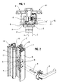
- the opening frame corresponding to leaf A, has a cover strip C which is applied on a support edge D of the other leaf B.
- this frame opening the overlapping leaf A receives, in rebate of its front upright, a locking fitting E coming from fit into an installation groove F provided for this purpose.
- the axis I of the follower corresponding to the control mechanism of the locking fitting E is substantially offset, horizontally, relative to the plane median J of the beat G to which is reported, so centered, the control handle K and, therefore, the operating square M of the latter.
- follower N which takes position between the handle K and the lock fitting housing E.
- this follower return device N in the form of a case, takes position in a notch O practiced from the rebate in the cover strip C. In Consequently, such a cut O defines, at the level of this strip of overlap C an interruption in the seal, breaking the groove R of the covering strip C, which it provides in cooperation with the support edge D of the other leaf B.
- the N follower return device As for the N follower return device, the details of which do not appear in these figures 1 and 2 corresponding to the state of the technique, it comes in the form of a box in which are mounted in rotation, around parallel axes, on the one hand, a primary gable-nut crossed in its center by an opening for the reception of a maneuvering square coming to cooperate, by elsewhere, with the nut of the control mechanism of the fitting of locking E. On the other hand, in this housing is mounted a pinion-nut secondary itself crossed by an opening for the reception of the operating square of the control handle K.
- These primary and secondary sprocket gears are engaged one with the other through reversing gears, in particular the number of two, allowing, when rotated by the handle control gear K of the secondary pinion in a specified direction, that it results in a rotation in the same direction of the pinion-follower primary.
- the present invention is intended to to provide a solution to make such an easily adaptable follower return device to any type of profile constituting the opening frame of a door, window or the like, in particular regardless of the thickness of the profile, therefore the distance separating the internal side of the latter from the internal side of the housing locking fitting control mechanism.
- the invention relates to a device for returning follower as defined in claim 1.
- the secondary sprocket and / or primary sprocket are subdivided, in their axial direction, into two cylindrical portions of which a first has teeth capable of meshing with the pinion reverser, the second portion comprising in its center, a primary and / or secondary opening for the reception of the primary and / or secondary operating square of the handle and / or the control mechanism and substantially constituting said primary and / or secondary coupling means.
- the portion of the pinion-nut secondary and / or primary gear, provided with the opening for receiving the handle operating square and / or of the control mechanism, is at least partially emerging from the housing, on the side opposite the handle and / or said mechanism ordered.
- the pinion-nut primary and / or secondary sprocket is extended, axially, by a primary and / or secondary operating square made in one piece with this gable and projecting from the side of the housing opposite the housing of the locking fitting and / or of the handle.
- a fur forming a spacer of the type interchangeable, to adapt to the distance between the case of said device of the case of the locking fitting.
- said primary and / or secondary coupling means are defined by an intermediate piece comprising, on the one hand, at one end of the fitting means males or females provided to cooperate with nesting means of conjugate form females or males which comprises the pinion-nut primary and / or secondary sprocket and, secondly, a extension, either in the form of a primary and / or secondary operating square coming present protruding from the side of the housing opposite the fitting of locking and / or handle, either comprising in its center a opening for receiving the primary and / or secondary operating square of this handle and / or this control mechanism.
- the return device follower capable of receiving fixing means by clipping to ensure its connection to the housing of the fitting locking, such means of fixing by clipping being, there again, of an interchangeable nature to be adjusted to the distance between said boxes.
- the present invention relates to a device for returning follower 1 which will find a very particular utility within the framework of a situation as visible in Figures 1 and 2 which, they correspond to the state of the art.
- this opening frame 3 includes a covering strip 4 intended for apply on a support edge 5 of the front upright 6 corresponding to the opening frame 7, here represented so partial schematic and in broken lines.
- the front pillar 6, corresponding to the other chassis opening 7 receives an external thrust (not shown) coming close, from the outside, the rebate clearance between the uprights front 2 and 6.
- an internal swaging 10 This is in the form of a profile often centered in relation to the median plane 11 of this double leaf door or window.
- control handle 13 takes position in the middle of this internal beat 10.
- the axis of the square of operation 15 of this control handle 13 is not located at right of axis 16 of the follower corresponding to the control mechanism 17 of said locking fitting 14.
- this one therefore the housing 18 containing this control mechanism 17, comes to take position in a recess groove 19 provided in rebate 20 the front upright 2 corresponding to the opening frame 3.
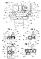
- the device for follower 1 comprises a housing 22 in which are rotatably mounted about axes 23, 24 parallel, on the one hand, a primary-pinion gear 25 intended to cooperate, at across a primary operating square 26, with the follower of the control 17 of the locking fitting 14, here shown under in the form of a lever, and on the other hand, a secondary pinion 27 provided to accommodate the secondary operating square 15 of the handle 13.
- This primary pinion gear 25 and the pinion gear secondary 27 are meshed through at least one pinion reverser 28, 29 also mounted for rotation in the housing 22. It is designed to take a position in the thickness of the opening frame 3, between the housing 18 corresponding to the fitting of lock 14 and said control handle 13.
- the primary sprocket 25 and / or secondary sprocket 27 have primary and / or secondary coupling means designed to cooperate with the primary and / or secondary operating square 26; 15, as the case may be, of the control mechanism 17 of the locking fitting 14 or of the handle 13, lying outside of said PL gear plan.
- the secondary pinion gear 27 is subdivided, in its axial direction, into two cylindrical portions 30, 31, including a first portion 30 has teeth capable of meshing with the reversing pinion (s) 28, 29.
- the second portion 31, substantially defining the secondary coupling means, has, in its center, the opening 32 for receiving the secondary operating square 15 from the control handle 13.
- this can be defined with a diameter of 33 smaller, facilitating its juxtaposition in the same plane, at the primary pinion gear 25, taking into account the spacing respect between axis 23 of the latter with respect to axis 24 of secondary sprocket 27.
- This spacing very match exactly at the offset between the secondary operating square 15 of the handle 13 and the axis 16 of the follower corresponding to the control 17 of the locking fitting 14.
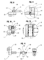
- the portion 31 of the secondary pinion 27, provided of the opening 32 for the reception of the secondary operating square 15 of the control handle 13, may be at least partially emerging of this housing 22, on the side 36 oriented towards said control handle 13. In the end, as shown in this figure 5 this allows to further reduce this thickness 34 of the housing 22.
- the primary pinion gear 25 could be subdivided, in the same way, in two portions and borrow, thus, a configuration similar to the secondary sprocket 27.
- the portion provided with an opening for the reception of the primary operating square corresponding to the control 17 is likely to emerge from the housing 22, on the side of this latest.
- the pinion primary 25 is extended, axially, by a primary operating square 26 defining said primary coupling means. So this square of primary operation 26, made in one piece with this pinion 25, comes present protruding from the side 37 of the housing 22 opposite the housing 18 of the locking fitting 14, in order to cooperate with the control mechanism 17 of the latter.
- said primary and / or secondary coupling means can be defined by an intermediate piece 50 comprising, on the one hand, at one end 51 of the male fitting means or 52 females provided to cooperate with means of interlocking females or males conjugate form 53 that includes the pinion primary 25 and / or secondary pinion 27 and, on the other hand, an extension 54; 54A, either in the form of an operating square coming forward projecting from the side 37; 36 of the housing 22 opposite of the control mechanism 17 of the locking fitting 14 or of the handle 13, that is to say comprising in its center an opening for the reception of the operating square 15; 26 of this handle 13 or of this control mechanism 17.
- these primary and secondary pinion gears 25 27 have a section, respectively 38 and 33, independent of that of the primary operating square 26 respectively secondary 15, this section 38, 33 can be adapted to almost any type of spacing currently meets between axis 16 of a follower of a fitting of lock 17 and plane 11 in which the handle is located 13.
- the housing 22, width 35 and thickness 34 reduced is able, under these conditions, to take position in the thickness 39 even of the covering strip 4, which can also be cut, not from the edge before 21 of the upright 2 of the opening frame 3, but from its internal side 9.
- the solution according to the invention avoids cutting the edge front of the cover strip 4, design which required the use of a cover P visible in Figure 2 to close this notching after mounting, carried out simultaneously on the fitting locking device and follower return device.
- the distance 41 separating the side internal of the cover strip 4 and the internal side of the housing 18 of the locking fitting 14 may vary in depending on the type of profile used for the design of a chassis opening 3.
- a sheath 42 on the primary operating square 26 of the pinion-follower primary 25 can be engaged a sheath 42, forming spacer between the housing 22 of this device and the housing 18 enclosing the control mechanism 17 of the locking fitting 14.
- a sheath 42 comprising an opening 43 for the passage of said operating square 26, can be designed as a part made of synthetic material, thickness 44 adapted to this distance between boxes 18 and 22.
- this sheath 42 can receive, at this opening 43, breakable indexing means 45 for immobilization in rotation temporary of the primary operating square 26, prior to mounting the device for returning the follower 1 to the opening frame 3, therefore before engagement of said primary operating square 26 in the follower of the control mechanism 17 of the locking fitting 14.
- breakable indexing means 45 can adopt different embodiments.
- they may present in the form of a tab 46 which is inserted into a notch 47 provided at the periphery of the primary operating square 26, or even at the primary sprocket 27.
- such a sheath 42 could as well be engaged on the extension 54 of an intermediate piece 50 associated with the pinion-follower primary 25, or even on a possible portion emerging from the housing 22, on the side 37 of the fitting 14, and comprising an opening for the reception of a maneuvering square, as shown above about an embodiment of the invention.
- the housing 22 of this device 1 can, quite simply, be clipped and no longer screwed onto the housing 18 of the locking fitting 14.
- the invention advantageously responds to the problem posed and therefore represents a clear progress in this field of returning devices.
Claims (11)
- Vorrichtung für den Antrieb einer Nuss, umfassend ein Gehäuse (22), in dem um parallele Achsen (23, 24) drehbar gelagert sind einerseits ein primäres Nussritzel (25) mit primären Kupplungsmitteln, die vorgesehen sind, über einen primären Vierkantdorn (26) mit einer Nuss eines Betätigungsmechanismus (17) in einem Gehäuse (18) eines Verriegelungsbeschlags (14) vom Typ Treibstangenbeschlag zusammenzuwirken, das in einer Einbaunut (19) angeordnet ist, die im Falz (20) eines mit einem Abdeckband (4) versehenen Flügels (3) vorgesehen ist, und andererseits ein sekundäres Nussritzel (27) mit sekundären Kupplungsmitteln, die für einen sekundären Vierkantdorn (15) eines Betätigungsgriffs (13) vorgesehen sind, der an der Innenseite des Flügels (3) aufgesetzt angeordnet ist, wobei das primäre Nussritzel (25) und das sekundäre Nussritzel (27) über mindestens ein Umkehrzahnrad (28, 29) in Eingriff kommen, das ebenso in dem Gehäuse (22) drehbar gelagert ist, das dafür bestimmt ist, in der Dicke des Flügels (3) zwischen dem Gehäuse (18) des Beschlags (14) und dem Betätigungsgriff (13) aufgenommen zu werden, wobei das primäre Nussritzel (25) und das sekundäre Nussritzel (27) in einer gleichen Eingriffsebene (PL) im Innern des Gehäuses (22) dieser Vorrichtung angeordnet sind, dadurch gekennzeichnet, dass sich die primären und/oder sekundären Kupplungsmittel außerhalb dieser Eingriffsebene (PL) befinden.
- Vorrichtung für den Antrieb einer Nuss entsprechend Anspruch 1, dadurch gekennzeichnet, dass das sekundäre Nussritzel (27) und/oder primäre Nussritzel (25) in ihrer axialen Richtung in zwei zylindrische Bereiche (30, 31) unterteilt sind, wovon der erste (30) eine Verzahnung trägt, die geeignet ist, in das Umkehrzahnrad (28, 29) einzugreifen, wobei der zweite Bereich (31) in seiner Mitte eine primäre und/oder sekundäre Öffnung (32) aufweist für die Aufnahme des primären und/oder sekundären Vierkantdorns (15) des Betätigungsgriffs (13) und/oder des Betätigungsmechanismus (17) und im wesentlichen die primären und/oder sekundären Kupplungsmittel bildet.
- Vorrichtung für den Antrieb einer Nuss entsprechend Anspruch 2, dadurch gekennzeichnet, dass der Bereich (31) des sekundären Nussritzels (27) und/oder des primären Nussritzels (25), der mit der Öffnung (32) für die Aufnahme des Vierkantdorns (15; 26) des Betätigungsgriffs (13) und/oder des Betätigungsmechanismus (17) versehen ist, auf der dem Betätigungsgriff (13) und/oder dem Betätigungsmechanismus (17) zugewandten Seite (36; 37) zumindest teilweise aus dem Gehäuse (22) herausragt.
- Vorrichtung für den Antrieb einer Nuss entsprechend einem der vorangegangenen Ansprüche, dadurch gekennzeichnet, dass das primäre Nussritzel (25) und/oder das sekundäre Nussritzel (27) sich in axialer Richtung über einen primären und/oder sekundären Vierkantdorn (26) fortsetzt, der einstückig mit dem Ritzel (25; 27) ausgebildet ist, auf der dem Verriegelungsbeschlag (14) und/oder dem Griff (13) zugewandten Seite (37; 36) des Gehäuses (22) vorspringt und im wesentlichen die primären und/oder sekundären Kupplungsmittel bildet.
- Vorrichtung für den Antrieb einer Nuss entsprechend einem der vorangegangenen Ansprüche, dadurch gekennzeichnet, dass die primären und/oder sekundären Kupplungsmittel von einem Zwischenstück (50) gebildet werden, das einerseits ein Ende (51) von stecker- oder buchsenförmigen Eingriffsmitteln (52) aufweist für das Zusammenwirken mit stecker- oder buchsenförmigen Eingriffsmitteln (53) von komplementärer Form, die das primäre Nussritzel (25) und/oder das sekundäre Nussritzel (27) aufweist, und andererseits einen Fortsatz (54; 54A) aufweist, entweder in Form eines primären und/oder sekundären Vierkantdorns, der auf der dem Verriegelungsbeschlag (14) und/oder dem Griff (13) zugewandten Seite (37; 36) des Gehäuses (22) vorspringt, oder der in seiner Mitte eine Öffnung für die Aufnahme des primären und/oder sekundären Vierkantdorns (15; 26) des Betätigungsgriffs (13) und/oder des Betätigungsmechanismus (17) aufweist.
- Vorrichtung für den Antrieb einer Nuss entsprechend einem der Ansprüche 1 bis 5, dadurch gekennzeichnet, dass ihr Gehäuse mit geeigneter Dicke (34) und Breite (35) (22) ausgebildet ist, um in der Dicke (39) eines Überschlags (4) eines Flügels (3) mit Überschlag einer Tür, eines Fensters oder dergleichen in einer Vertiefung (40) aufgenommen zu werden, die an der Innenseite (9) des Raumes dieses Überschlags (4) ausgebildet ist.
- Vorrichtung für den Antrieb einer Nuss entsprechend einem der vorangegangenen Ansprüche, dadurch gekennzeichnet, dass sich der sekundäre Vierkantdorn (15) oder der an der Seite (36) des Gehäuses (22) herausragende Bereich oder der Fortsatz (54A) des Zwischenstücks (50), das dem sekundären Nussritzel (27) zugeordnet ist, in eine Öffnung erstreckt, die in einem Anschlag (10) vorgesehen ist, der an der Innenseite (9) des Abdeckbandes (4) angeordnet ist.
- Vorrichtung für den Antrieb einer Nuss entsprechend einem der vorangegangenen Ansprüche, dadurch gekennzeichnet, dass auf dem primären Vierkantdorn (26) oder auf dem an der Seite (36) des Gehäuses (22) herausragenden Bereich oder auf dem Fortsatz (54) des dem primären Nussritzel (25) zugeordneten Zwischenstücks (50) eine Manschette (42) aufgesteckt ist, die ein Abstandsstück zwischen dem Gehäuse (22) der Vorrichtung (1) und dem Gehäuse (18) bildet, das den Betätigungsmechanismus (17) des Verriegelungsbeschlags (14) enthält.
- Vorrichtung für den Antrieb einer Nuss entsprechend Anspruch 8, dadurch gekennzeichnet, dass die das Abstandsstück bildende Manschette (42) an der Öffnung (43) für den Durchtritt des primären Vierkantdorns (26) oder des dem primären Nussritzel (25) zugeordneten herausragenden Bereichs oder des Fortsatzes (54) des Zwischenstücks (50) teilbare Indexiermittel (45) aufweist zum vorübergehenden Sperren der Drehbewegung des primären Nussritzels (25).
- Vorrichtung für den Antrieb einer Nuss entsprechend einem der vorangegangenen Ansprüche, dadurch gekennzeichnet, dass ihr Gehäuse (22) dafür vorgesehen ist, Mittel zum Befestigen mittels Aufklippsen (48) aufzunehmen, um die Verbindung mit dem Gehäuse (18) des Verriegelungsbeschlags (14) herzustellen, wobei derartige Mittel zum Befestigen mittels Aufklippsen (48) untereinander austauschbar sind, um an den Abstand zwischen den Gehäusen (18) und (22) angepasst zu werden.
- Vorrichtung für den Antrieb einer Nuss entsprechend Anspruch 10, dadurch gekennzeichnet, dass die Mittel zum Befestigen mittels Aufklippsen (48) von zwei mit Haltemitteln (51) versehenen Ansatzstücken (49, 50) in Form von Vorsprüngen oder dergleichen gebildet werden, die sich beiderseits eines Elements erstrecken, das das Abstandsstück (52) bildet, dessen Dicke (55) an den Abstand zwischen dem Gehäuse (22) der Vorrichtung zum Antrieb der Nuss (1) und dem Gehäuse (18) des Verriegelungsbeschlags (14) angepasst ist, wobei das Ansatzstück (49) derart angepasst ist, dass es in eine zu diesem Zweck in dem Gehäuse (22) vorgesehene Öffnung (53) einrasten kann, während das Ansatzstück (50) in der Lage ist, mit einer Öffnung (54) in dem Gehäuse (18) zusammenzutreffen.
Applications Claiming Priority (2)
| Application Number | Priority Date | Filing Date | Title |
|---|---|---|---|
| FR9907609A FR2794787B1 (fr) | 1999-06-11 | 1999-06-11 | Dispositif de renvoi de fouillot |
| FR9907609 | 1999-06-11 |
Publications (3)
| Publication Number | Publication Date |
|---|---|
| EP1059409A1 EP1059409A1 (de) | 2000-12-13 |
| EP1059409B1 true EP1059409B1 (de) | 2004-04-14 |
| EP1059409B9 EP1059409B9 (de) | 2006-01-18 |
Family
ID=9546861
Family Applications (1)
| Application Number | Title | Priority Date | Filing Date |
|---|---|---|---|
| EP00440168A Expired - Lifetime EP1059409B9 (de) | 1999-06-11 | 2000-06-09 | Antriebsgetriebe für Schlossnuss |
Country Status (6)
| Country | Link |
|---|---|
| EP (1) | EP1059409B9 (de) |
| AT (1) | ATE264444T1 (de) |
| DE (1) | DE60009792T2 (de) |
| DK (1) | DK1059409T3 (de) |
| ES (1) | ES2219287T3 (de) |
| FR (1) | FR2794787B1 (de) |
Families Citing this family (7)
| Publication number | Priority date | Publication date | Assignee | Title |
|---|---|---|---|---|
| DE50111018D1 (de) * | 2001-10-09 | 2006-10-26 | Hautau Gmbh | Z-Förmige Getriebeanordnung |
| FR2844539B1 (fr) | 2002-09-17 | 2004-12-03 | Ferco Int Usine Ferrures | Organe de manoeuvre de type poignee pour porte, fenetre ou autre |
| FR2919887B1 (fr) * | 2007-08-09 | 2009-10-09 | Ferco Internat Ferrures Serrur | Ferrure de type cremone ou cremone-serrure |
| FR2923252A1 (fr) * | 2007-11-02 | 2009-05-08 | Ferco Int Usine Ferrures | Dispositif d'entrainement pour ferrure de verrouillage de type cremone ou cremone-serrure |
| FR2952109B1 (fr) * | 2009-10-29 | 2011-12-23 | Ferco Int Usine Ferrures | Cremone ou cremone-serrure |
| DE102014117419A1 (de) * | 2014-11-27 | 2016-06-02 | Maco Technologie Gmbh | Beschlag für Fenster, Türen und dergleichen und Getriebeeinheit für einen solchen Beschlag |
| FR3043117B1 (fr) | 2015-11-04 | 2022-10-28 | Jean Luc Ricevuto | Poignee de fenetre a fixation par le carre |
Family Cites Families (5)
| Publication number | Priority date | Publication date | Assignee | Title |
|---|---|---|---|---|
| DE2515989A1 (de) * | 1975-04-12 | 1976-10-21 | Stucke Lothar | Kantengetriebe fuer ein fenster, eine tuer o.dgl. |
| DE8203945U1 (de) * | 1982-02-12 | 1982-05-19 | Wilh. Frank Gmbh, 7022 Leinfelden-Echterdingen | Kantengetriebe fuer ein fenster, eine tuer od. dgl. |
| DE9100436U1 (de) * | 1991-01-15 | 1991-04-04 | Roto Frank Ag, 7022 Leinfelden-Echterdingen, De | |
| DE9103676U1 (de) * | 1991-03-26 | 1991-07-04 | Gretsch-Unitas Gmbh Baubeschlaege, 7257 Ditzingen, De | |
| GB2310456B (en) * | 1996-02-20 | 2000-09-06 | Derek King | Shoot bolt window locking system |
-
1999
- 1999-06-11 FR FR9907609A patent/FR2794787B1/fr not_active Expired - Fee Related
-
2000
- 2000-06-09 DE DE60009792T patent/DE60009792T2/de not_active Expired - Lifetime
- 2000-06-09 DK DK00440168T patent/DK1059409T3/da active
- 2000-06-09 EP EP00440168A patent/EP1059409B9/de not_active Expired - Lifetime
- 2000-06-09 ES ES00440168T patent/ES2219287T3/es not_active Expired - Lifetime
- 2000-06-09 AT AT00440168T patent/ATE264444T1/de not_active IP Right Cessation
Also Published As
| Publication number | Publication date |
|---|---|
| DE60009792D1 (de) | 2004-05-19 |
| ATE264444T1 (de) | 2004-04-15 |
| DE60009792T2 (de) | 2005-03-31 |
| FR2794787B1 (fr) | 2002-05-10 |
| EP1059409A1 (de) | 2000-12-13 |
| DK1059409T3 (da) | 2004-08-02 |
| FR2794787A1 (fr) | 2000-12-15 |
| ES2219287T3 (es) | 2004-12-01 |
| EP1059409B9 (de) | 2006-01-18 |
Similar Documents
| Publication | Publication Date | Title |
|---|---|---|
| EP0274975B1 (de) | Sicherheitsbeschlag für Tür oder Fenster mit Mitteln zum Verriegeln des Vierkantstiftes | |
| EP1059409B1 (de) | Antriebsgetriebe für Schlossnuss | |
| EP0952284A1 (de) | Verriegelungsvorrichtung für einen Schiebeflügel | |
| EP2173953B1 (de) | Verbindungsvorrichtung zur herstellung einer verbindung zwischen dem türriegel und dem türverschluss eines motorfahrzeugs | |
| EP2415954B1 (de) | Einsatzbeschlag, der einen Befestigungsflansch umfasst | |
| EP2206869A1 (de) | Vorrichtung für die Motorisierung eines Fensters oder des Öffnungselements eines Schiebefensters | |
| EP1063378B1 (de) | Verdeckter Öffnungsbeschlag für Drehflügeltür oder -Fenster | |
| FR2838155A1 (fr) | Chassis de fenetre comportant un chassis vitre pivotant a l'interieur | |
| FR2755720A1 (fr) | Dispositif de manoeuvre et de fermeture pour une espagnolette, equipe de moyens de blocage temporaire | |
| FR2689171A1 (fr) | Dispositif de commande d'un vantail de porte ou portail. | |
| FR3096714A3 (fr) | Charnière de type à peigne pour fenêtre et portes à vantail pivotant | |
| BE1015014A4 (fr) | Ferrure de verrouillage d'ouvrant dotee pour sa fixation de moyens d'appui interieur et exterieur decales et ouvrant equipe d'une telle ferrure. | |
| FR2666369A1 (fr) | Ferrure pour une fenetre, une porte, ou similaire. | |
| FR2583452A1 (fr) | Boitier de cremone a plaquer avec condamnation. | |
| FR2610352A1 (fr) | Plaque pour poignee de porte | |
| FR2952109A1 (fr) | Cremone ou cremone-serrure | |
| FR2923252A1 (fr) | Dispositif d'entrainement pour ferrure de verrouillage de type cremone ou cremone-serrure | |
| FR2854919A1 (fr) | Dispositif de blocage pour verrou de vantail de porte, fenetre ou similaire | |
| EP0395554B1 (de) | Betätigungsgriff für Türen, Fenstertüren oder dergleichen | |
| EP0869245B1 (de) | Beschlag für Schiebetür, Schiebefenster oder ähnliches | |
| FR2715428A1 (fr) | Serrure de sûreté pour coffrets d'appareillages techniques. | |
| EP0992646B1 (de) | Treibstange oder Treibstangenschloss für Türen, Fenster oder dergleichen | |
| EP1475497A1 (de) | Sperriegel für Tür- oder Fensterflügel | |
| EP4050182A1 (de) | Vorrichtung zur steuerung eines verriegelungs-/entriegelungsmechanismus eines öffnungsflügels | |
| FR2786803A1 (fr) | Ferrure de verrouillage de type cremone |
Legal Events
| Date | Code | Title | Description |
|---|---|---|---|
| PUAI | Public reference made under article 153(3) epc to a published international application that has entered the european phase |
Free format text: ORIGINAL CODE: 0009012 |
|
| AK | Designated contracting states |
Kind code of ref document: A1 Designated state(s): AT BE CH CY DE DK ES FI FR GB GR IE IT LI LU MC NL PT SE |
|
| AX | Request for extension of the european patent |
Free format text: AL;LT;LV;MK;RO;SI |
|
| 17P | Request for examination filed |
Effective date: 20010122 |
|
| AKX | Designation fees paid |
Free format text: AT BE CH CY DE DK ES FI FR GB GR IE IT LI LU MC NL PT SE |
|
| GRAP | Despatch of communication of intention to grant a patent |
Free format text: ORIGINAL CODE: EPIDOSNIGR1 |
|
| GRAS | Grant fee paid |
Free format text: ORIGINAL CODE: EPIDOSNIGR3 |
|
| GRAA | (expected) grant |
Free format text: ORIGINAL CODE: 0009210 |
|
| AK | Designated contracting states |
Kind code of ref document: B1 Designated state(s): AT BE CH CY DE DK ES FI FR GB GR IE IT LI LU MC NL PT SE |
|
| PG25 | Lapsed in a contracting state [announced via postgrant information from national office to epo] |
Ref country code: NL Free format text: LAPSE BECAUSE OF FAILURE TO SUBMIT A TRANSLATION OF THE DESCRIPTION OR TO PAY THE FEE WITHIN THE PRESCRIBED TIME-LIMIT Effective date: 20040414 Ref country code: IE Free format text: LAPSE BECAUSE OF FAILURE TO SUBMIT A TRANSLATION OF THE DESCRIPTION OR TO PAY THE FEE WITHIN THE PRESCRIBED TIME-LIMIT Effective date: 20040414 Ref country code: CY Free format text: LAPSE BECAUSE OF FAILURE TO SUBMIT A TRANSLATION OF THE DESCRIPTION OR TO PAY THE FEE WITHIN THE PRESCRIBED TIME-LIMIT Effective date: 20040414 Ref country code: FI Free format text: LAPSE BECAUSE OF FAILURE TO SUBMIT A TRANSLATION OF THE DESCRIPTION OR TO PAY THE FEE WITHIN THE PRESCRIBED TIME-LIMIT Effective date: 20040414 Ref country code: AT Free format text: LAPSE BECAUSE OF FAILURE TO SUBMIT A TRANSLATION OF THE DESCRIPTION OR TO PAY THE FEE WITHIN THE PRESCRIBED TIME-LIMIT Effective date: 20040414 |
|
| REG | Reference to a national code |
Ref country code: GB Ref legal event code: FG4D Free format text: NOT ENGLISH |
|
| REG | Reference to a national code |
Ref country code: CH Ref legal event code: EP |
|
| REF | Corresponds to: |
Ref document number: 60009792 Country of ref document: DE Date of ref document: 20040519 Kind code of ref document: P |
|
| REG | Reference to a national code |
Ref country code: IE Ref legal event code: FG4D Free format text: FRENCH |
|
| PG25 | Lapsed in a contracting state [announced via postgrant information from national office to epo] |
Ref country code: LU Free format text: LAPSE BECAUSE OF NON-PAYMENT OF DUE FEES Effective date: 20040609 |
|
| PG25 | Lapsed in a contracting state [announced via postgrant information from national office to epo] |
Ref country code: MC Free format text: LAPSE BECAUSE OF NON-PAYMENT OF DUE FEES Effective date: 20040630 Ref country code: LI Free format text: LAPSE BECAUSE OF NON-PAYMENT OF DUE FEES Effective date: 20040630 Ref country code: CH Free format text: LAPSE BECAUSE OF NON-PAYMENT OF DUE FEES Effective date: 20040630 |
|
| PG25 | Lapsed in a contracting state [announced via postgrant information from national office to epo] |
Ref country code: SE Free format text: LAPSE BECAUSE OF FAILURE TO SUBMIT A TRANSLATION OF THE DESCRIPTION OR TO PAY THE FEE WITHIN THE PRESCRIBED TIME-LIMIT Effective date: 20040714 Ref country code: GR Free format text: LAPSE BECAUSE OF FAILURE TO SUBMIT A TRANSLATION OF THE DESCRIPTION OR TO PAY THE FEE WITHIN THE PRESCRIBED TIME-LIMIT Effective date: 20040714 |
|
| REG | Reference to a national code |
Ref country code: DK Ref legal event code: T3 |
|
| GBT | Gb: translation of ep patent filed (gb section 77(6)(a)/1977) |
Effective date: 20040721 |
|
| NLV1 | Nl: lapsed or annulled due to failure to fulfill the requirements of art. 29p and 29m of the patents act | ||
| REG | Reference to a national code |
Ref country code: IE Ref legal event code: FD4D Ref country code: ES Ref legal event code: FG2A Ref document number: 2219287 Country of ref document: ES Kind code of ref document: T3 |
|
| REG | Reference to a national code |
Ref country code: CH Ref legal event code: PL |
|
| PLBE | No opposition filed within time limit |
Free format text: ORIGINAL CODE: 0009261 |
|
| STAA | Information on the status of an ep patent application or granted ep patent |
Free format text: STATUS: NO OPPOSITION FILED WITHIN TIME LIMIT |
|
| 26N | No opposition filed |
Effective date: 20050117 |
|
| PGFP | Annual fee paid to national office [announced via postgrant information from national office to epo] |
Ref country code: GB Payment date: 20050608 Year of fee payment: 6 |
|
| PGFP | Annual fee paid to national office [announced via postgrant information from national office to epo] |
Ref country code: DK Payment date: 20050614 Year of fee payment: 6 |
|
| PGFP | Annual fee paid to national office [announced via postgrant information from national office to epo] |
Ref country code: BE Payment date: 20050810 Year of fee payment: 6 |
|
| PG25 | Lapsed in a contracting state [announced via postgrant information from national office to epo] |
Ref country code: GB Free format text: LAPSE BECAUSE OF NON-PAYMENT OF DUE FEES Effective date: 20060609 |
|
| PG25 | Lapsed in a contracting state [announced via postgrant information from national office to epo] |
Ref country code: DK Free format text: LAPSE BECAUSE OF NON-PAYMENT OF DUE FEES Effective date: 20060630 Ref country code: BE Free format text: LAPSE BECAUSE OF NON-PAYMENT OF DUE FEES Effective date: 20060630 |
|
| REG | Reference to a national code |
Ref country code: DK Ref legal event code: EBP |
|
| GBPC | Gb: european patent ceased through non-payment of renewal fee |
Effective date: 20060609 |
|
| BERE | Be: lapsed |
Owner name: S.A. *FERCO INTERNATIONAL FERRURES ET SERRURES DE Effective date: 20060630 |
|
| PG25 | Lapsed in a contracting state [announced via postgrant information from national office to epo] |
Ref country code: PT Free format text: LAPSE BECAUSE OF NON-PAYMENT OF DUE FEES Effective date: 20040914 |
|
| PGFP | Annual fee paid to national office [announced via postgrant information from national office to epo] |
Ref country code: ES Payment date: 20140627 Year of fee payment: 15 Ref country code: DE Payment date: 20140619 Year of fee payment: 15 |
|
| PGFP | Annual fee paid to national office [announced via postgrant information from national office to epo] |
Ref country code: IT Payment date: 20140630 Year of fee payment: 15 |
|
| REG | Reference to a national code |
Ref country code: DE Ref legal event code: R082 Ref document number: 60009792 Country of ref document: DE |
|
| REG | Reference to a national code |
Ref country code: DE Ref legal event code: R119 Ref document number: 60009792 Country of ref document: DE |
|
| PG25 | Lapsed in a contracting state [announced via postgrant information from national office to epo] |
Ref country code: IT Free format text: LAPSE BECAUSE OF NON-PAYMENT OF DUE FEES Effective date: 20150609 |
|
| PG25 | Lapsed in a contracting state [announced via postgrant information from national office to epo] |
Ref country code: DE Free format text: LAPSE BECAUSE OF NON-PAYMENT OF DUE FEES Effective date: 20160101 |
|
| REG | Reference to a national code |
Ref country code: FR Ref legal event code: PLFP Year of fee payment: 17 |
|
| REG | Reference to a national code |
Ref country code: ES Ref legal event code: FD2A Effective date: 20160727 |
|
| PG25 | Lapsed in a contracting state [announced via postgrant information from national office to epo] |
Ref country code: ES Free format text: LAPSE BECAUSE OF NON-PAYMENT OF DUE FEES Effective date: 20150610 |
|
| REG | Reference to a national code |
Ref country code: FR Ref legal event code: PLFP Year of fee payment: 18 |
|
| REG | Reference to a national code |
Ref country code: FR Ref legal event code: PLFP Year of fee payment: 19 |
|
| PGFP | Annual fee paid to national office [announced via postgrant information from national office to epo] |
Ref country code: FR Payment date: 20190619 Year of fee payment: 20 |