EP1059409B1 - Drive gear for a lock follower - Google Patents
Drive gear for a lock follower Download PDFInfo
- Publication number
- EP1059409B1 EP1059409B1 EP00440168A EP00440168A EP1059409B1 EP 1059409 B1 EP1059409 B1 EP 1059409B1 EP 00440168 A EP00440168 A EP 00440168A EP 00440168 A EP00440168 A EP 00440168A EP 1059409 B1 EP1059409 B1 EP 1059409B1
- Authority
- EP
- European Patent Office
- Prior art keywords
- primary
- pinion
- casing
- tumbler
- drive gear
- Prior art date
- Legal status (The legal status is an assumption and is not a legal conclusion. Google has not performed a legal analysis and makes no representation as to the accuracy of the status listed.)
- Expired - Lifetime
Links
Images
Classifications
-
- E—FIXED CONSTRUCTIONS
- E05—LOCKS; KEYS; WINDOW OR DOOR FITTINGS; SAFES
- E05C—BOLTS OR FASTENING DEVICES FOR WINGS, SPECIALLY FOR DOORS OR WINDOWS
- E05C9/00—Arrangements of simultaneously actuated bolts or other securing devices at well-separated positions on the same wing
- E05C9/02—Arrangements of simultaneously actuated bolts or other securing devices at well-separated positions on the same wing with one sliding bar for fastening when moved in one direction and unfastening when moved in opposite direction; with two sliding bars moved in the same direction when fastening or unfastening
- E05C9/021—Arrangements of simultaneously actuated bolts or other securing devices at well-separated positions on the same wing with one sliding bar for fastening when moved in one direction and unfastening when moved in opposite direction; with two sliding bars moved in the same direction when fastening or unfastening with rack and pinion mechanism
-
- E—FIXED CONSTRUCTIONS
- E05—LOCKS; KEYS; WINDOW OR DOOR FITTINGS; SAFES
- E05C—BOLTS OR FASTENING DEVICES FOR WINGS, SPECIALLY FOR DOORS OR WINDOWS
- E05C9/00—Arrangements of simultaneously actuated bolts or other securing devices at well-separated positions on the same wing
- E05C9/10—Actuating mechanisms for bars
-
- E—FIXED CONSTRUCTIONS
- E05—LOCKS; KEYS; WINDOW OR DOOR FITTINGS; SAFES
- E05B—LOCKS; ACCESSORIES THEREFOR; HANDCUFFS
- E05B17/00—Accessories in connection with locks
- E05B17/0012—Accessories in connection with locks for lock parts held in place before or during mounting on the wing
-
- E—FIXED CONSTRUCTIONS
- E05—LOCKS; KEYS; WINDOW OR DOOR FITTINGS; SAFES
- E05C—BOLTS OR FASTENING DEVICES FOR WINGS, SPECIALLY FOR DOORS OR WINDOWS
- E05C7/00—Fastening devices specially adapted for two wings
- E05C7/04—Fastening devices specially adapted for two wings for wings which abut when closed
Definitions
- the present invention relates to the field of hardware building.
- the invention relates more particularly to a follower return device according to the preamble of claim 1.
- the opening frame corresponding to leaf A, has a cover strip C which is applied on a support edge D of the other leaf B.
- this frame opening the overlapping leaf A receives, in rebate of its front upright, a locking fitting E coming from fit into an installation groove F provided for this purpose.
- the axis I of the follower corresponding to the control mechanism of the locking fitting E is substantially offset, horizontally, relative to the plane median J of the beat G to which is reported, so centered, the control handle K and, therefore, the operating square M of the latter.
- follower N which takes position between the handle K and the lock fitting housing E.
- this follower return device N in the form of a case, takes position in a notch O practiced from the rebate in the cover strip C. In Consequently, such a cut O defines, at the level of this strip of overlap C an interruption in the seal, breaking the groove R of the covering strip C, which it provides in cooperation with the support edge D of the other leaf B.
- the N follower return device As for the N follower return device, the details of which do not appear in these figures 1 and 2 corresponding to the state of the technique, it comes in the form of a box in which are mounted in rotation, around parallel axes, on the one hand, a primary gable-nut crossed in its center by an opening for the reception of a maneuvering square coming to cooperate, by elsewhere, with the nut of the control mechanism of the fitting of locking E. On the other hand, in this housing is mounted a pinion-nut secondary itself crossed by an opening for the reception of the operating square of the control handle K.
- These primary and secondary sprocket gears are engaged one with the other through reversing gears, in particular the number of two, allowing, when rotated by the handle control gear K of the secondary pinion in a specified direction, that it results in a rotation in the same direction of the pinion-follower primary.
- the present invention is intended to to provide a solution to make such an easily adaptable follower return device to any type of profile constituting the opening frame of a door, window or the like, in particular regardless of the thickness of the profile, therefore the distance separating the internal side of the latter from the internal side of the housing locking fitting control mechanism.
- the invention relates to a device for returning follower as defined in claim 1.
- the secondary sprocket and / or primary sprocket are subdivided, in their axial direction, into two cylindrical portions of which a first has teeth capable of meshing with the pinion reverser, the second portion comprising in its center, a primary and / or secondary opening for the reception of the primary and / or secondary operating square of the handle and / or the control mechanism and substantially constituting said primary and / or secondary coupling means.
- the portion of the pinion-nut secondary and / or primary gear, provided with the opening for receiving the handle operating square and / or of the control mechanism, is at least partially emerging from the housing, on the side opposite the handle and / or said mechanism ordered.
- the pinion-nut primary and / or secondary sprocket is extended, axially, by a primary and / or secondary operating square made in one piece with this gable and projecting from the side of the housing opposite the housing of the locking fitting and / or of the handle.
- a fur forming a spacer of the type interchangeable, to adapt to the distance between the case of said device of the case of the locking fitting.
- said primary and / or secondary coupling means are defined by an intermediate piece comprising, on the one hand, at one end of the fitting means males or females provided to cooperate with nesting means of conjugate form females or males which comprises the pinion-nut primary and / or secondary sprocket and, secondly, a extension, either in the form of a primary and / or secondary operating square coming present protruding from the side of the housing opposite the fitting of locking and / or handle, either comprising in its center a opening for receiving the primary and / or secondary operating square of this handle and / or this control mechanism.
- the return device follower capable of receiving fixing means by clipping to ensure its connection to the housing of the fitting locking, such means of fixing by clipping being, there again, of an interchangeable nature to be adjusted to the distance between said boxes.
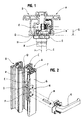
- the present invention relates to a device for returning follower 1 which will find a very particular utility within the framework of a situation as visible in Figures 1 and 2 which, they correspond to the state of the art.
- this opening frame 3 includes a covering strip 4 intended for apply on a support edge 5 of the front upright 6 corresponding to the opening frame 7, here represented so partial schematic and in broken lines.
- the front pillar 6, corresponding to the other chassis opening 7 receives an external thrust (not shown) coming close, from the outside, the rebate clearance between the uprights front 2 and 6.
- an internal swaging 10 This is in the form of a profile often centered in relation to the median plane 11 of this double leaf door or window.
- control handle 13 takes position in the middle of this internal beat 10.
- the axis of the square of operation 15 of this control handle 13 is not located at right of axis 16 of the follower corresponding to the control mechanism 17 of said locking fitting 14.
- this one therefore the housing 18 containing this control mechanism 17, comes to take position in a recess groove 19 provided in rebate 20 the front upright 2 corresponding to the opening frame 3.
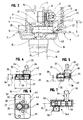
- the device for follower 1 comprises a housing 22 in which are rotatably mounted about axes 23, 24 parallel, on the one hand, a primary-pinion gear 25 intended to cooperate, at across a primary operating square 26, with the follower of the control 17 of the locking fitting 14, here shown under in the form of a lever, and on the other hand, a secondary pinion 27 provided to accommodate the secondary operating square 15 of the handle 13.
- This primary pinion gear 25 and the pinion gear secondary 27 are meshed through at least one pinion reverser 28, 29 also mounted for rotation in the housing 22. It is designed to take a position in the thickness of the opening frame 3, between the housing 18 corresponding to the fitting of lock 14 and said control handle 13.
- the primary sprocket 25 and / or secondary sprocket 27 have primary and / or secondary coupling means designed to cooperate with the primary and / or secondary operating square 26; 15, as the case may be, of the control mechanism 17 of the locking fitting 14 or of the handle 13, lying outside of said PL gear plan.
- the secondary pinion gear 27 is subdivided, in its axial direction, into two cylindrical portions 30, 31, including a first portion 30 has teeth capable of meshing with the reversing pinion (s) 28, 29.
- the second portion 31, substantially defining the secondary coupling means, has, in its center, the opening 32 for receiving the secondary operating square 15 from the control handle 13.
- this can be defined with a diameter of 33 smaller, facilitating its juxtaposition in the same plane, at the primary pinion gear 25, taking into account the spacing respect between axis 23 of the latter with respect to axis 24 of secondary sprocket 27.
- This spacing very match exactly at the offset between the secondary operating square 15 of the handle 13 and the axis 16 of the follower corresponding to the control 17 of the locking fitting 14.
- the portion 31 of the secondary pinion 27, provided of the opening 32 for the reception of the secondary operating square 15 of the control handle 13, may be at least partially emerging of this housing 22, on the side 36 oriented towards said control handle 13. In the end, as shown in this figure 5 this allows to further reduce this thickness 34 of the housing 22.
- the primary pinion gear 25 could be subdivided, in the same way, in two portions and borrow, thus, a configuration similar to the secondary sprocket 27.
- the portion provided with an opening for the reception of the primary operating square corresponding to the control 17 is likely to emerge from the housing 22, on the side of this latest.
- the pinion primary 25 is extended, axially, by a primary operating square 26 defining said primary coupling means. So this square of primary operation 26, made in one piece with this pinion 25, comes present protruding from the side 37 of the housing 22 opposite the housing 18 of the locking fitting 14, in order to cooperate with the control mechanism 17 of the latter.
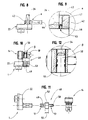
- said primary and / or secondary coupling means can be defined by an intermediate piece 50 comprising, on the one hand, at one end 51 of the male fitting means or 52 females provided to cooperate with means of interlocking females or males conjugate form 53 that includes the pinion primary 25 and / or secondary pinion 27 and, on the other hand, an extension 54; 54A, either in the form of an operating square coming forward projecting from the side 37; 36 of the housing 22 opposite of the control mechanism 17 of the locking fitting 14 or of the handle 13, that is to say comprising in its center an opening for the reception of the operating square 15; 26 of this handle 13 or of this control mechanism 17.
- these primary and secondary pinion gears 25 27 have a section, respectively 38 and 33, independent of that of the primary operating square 26 respectively secondary 15, this section 38, 33 can be adapted to almost any type of spacing currently meets between axis 16 of a follower of a fitting of lock 17 and plane 11 in which the handle is located 13.
- the housing 22, width 35 and thickness 34 reduced is able, under these conditions, to take position in the thickness 39 even of the covering strip 4, which can also be cut, not from the edge before 21 of the upright 2 of the opening frame 3, but from its internal side 9.
- the solution according to the invention avoids cutting the edge front of the cover strip 4, design which required the use of a cover P visible in Figure 2 to close this notching after mounting, carried out simultaneously on the fitting locking device and follower return device.
- the distance 41 separating the side internal of the cover strip 4 and the internal side of the housing 18 of the locking fitting 14 may vary in depending on the type of profile used for the design of a chassis opening 3.
- a sheath 42 on the primary operating square 26 of the pinion-follower primary 25 can be engaged a sheath 42, forming spacer between the housing 22 of this device and the housing 18 enclosing the control mechanism 17 of the locking fitting 14.
- a sheath 42 comprising an opening 43 for the passage of said operating square 26, can be designed as a part made of synthetic material, thickness 44 adapted to this distance between boxes 18 and 22.
- this sheath 42 can receive, at this opening 43, breakable indexing means 45 for immobilization in rotation temporary of the primary operating square 26, prior to mounting the device for returning the follower 1 to the opening frame 3, therefore before engagement of said primary operating square 26 in the follower of the control mechanism 17 of the locking fitting 14.
- breakable indexing means 45 can adopt different embodiments.
- they may present in the form of a tab 46 which is inserted into a notch 47 provided at the periphery of the primary operating square 26, or even at the primary sprocket 27.
- such a sheath 42 could as well be engaged on the extension 54 of an intermediate piece 50 associated with the pinion-follower primary 25, or even on a possible portion emerging from the housing 22, on the side 37 of the fitting 14, and comprising an opening for the reception of a maneuvering square, as shown above about an embodiment of the invention.
- the housing 22 of this device 1 can, quite simply, be clipped and no longer screwed onto the housing 18 of the locking fitting 14.
- the invention advantageously responds to the problem posed and therefore represents a clear progress in this field of returning devices.
Abstract
Description
La présente invention concerne le domaine de la quincaillerie du bâtiment.The present invention relates to the field of hardware building.
L'invention concerne plus particulièrement un dispositif de renvoi de fouillot selon le préamble de la revendication 1.The invention relates more particularly to a follower return device according to the preamble of claim 1.
Il existe, d'ores et déjà, des dispositifs de renvoi de fouillot
de ce type. A ce propos, pour mieux
comprendre cet état de la technique, on se rapportera aux figures 1
et 2 des dessins ci-joints tenant que :
En fait, cet état de la technique représenté dans ces figures 1 et 2 et qui est décrit plus en détail ci-dessous, correspond, plus particulièrement au document DE-U-91 03 676.In fact, this state of the art represented in these figures 1 and 2 and which is described in more detail below, corresponds, more particularly in document DE-U-91 03 676.
Ainsi, comme visible dans ces figures 1 et 2, le châssis ouvrant, correspondant au vantail A, comporte un bandeau de recouvrement C qui vient en applique sur un rebord d'appui D de l'autre vantail B. De plus, ce châssis ouvrant du vantail à recouvrement A reçoit, en feuillure de son montant avant, une ferrure de verrouillage E venant se loger dans une rainure d'encastrement F prévue à cet effet.Thus, as visible in these figures 1 and 2, the opening frame, corresponding to leaf A, has a cover strip C which is applied on a support edge D of the other leaf B. In addition, this frame opening the overlapping leaf A receives, in rebate of its front upright, a locking fitting E coming from fit into an installation groove F provided for this purpose.
L'on voit, encore, que du côté interne, le bandeau de recouvrement C de ce montant avant du vantail A reçoit une battée intérieure G, sous forme d'un profilé de finition donnant une certaine symétrie à l'ensemble, sans compter que cette battée G vient fermer la feuillure H (fig.1) existant entre les chants des vantaux A et B. Cette feuillure comporte, en dehors de la zone occupée par le dispositif de renvoi de fouillot, un joint (non représenté) logé dans une rainure R du bandeau de recouvrement (tel que visible figure 2).We see, again, that on the internal side, the cover strip C of this front upright of leaf A receives an internal swing G, in the form of a finishing profile giving a certain symmetry to the whole, not to mention that this beat G comes to close the rebate H (fig. 1) existing between the edges of leaves A and B. This rebate comprises, outside the area occupied by the follower return device, a seal (not shown) housed in a groove R of the cover strip (as visible figure 2).
Comme on le voit très bien sur cette figure 1, l'axe I du fouillot correspondant au mécanisme de commande de la ferrure de verrouillage E est sensiblement décalé, horizontalement, par rapport au plan médian J de la battée G sur laquelle est rapportée, de manière centrée, la poignée de commande K et, donc, le carré de manoeuvre M de cette dernière.As can be seen very clearly in this figure 1, the axis I of the follower corresponding to the control mechanism of the locking fitting E is substantially offset, horizontally, relative to the plane median J of the beat G to which is reported, so centered, the control handle K and, therefore, the operating square M of the latter.
Dans ces conditions, l'on fait appel à un dispositif de renvoi de fouillot N qui vient prendre position entre la poignée K et le boítier de la ferrure de verrouillage E. En fin de compte, comme visible dans ces figures 1 et 2, ce dispositif de renvoi de fouillot N, sous forme d'un boítier, prend position dans un entaillage O pratiqué depuis la feuillure dans le bandeau de recouvrement C. En conséquence, un tel entaillage O définit, au niveau de ce bandeau de recouvrement C une interruption dans l'étanchéité, en rompant la rainure R du bandeau de recouvrement C, qu'il assure en coopération avec le rebord d'appui D de l'autre vantail B.In these conditions, a call forwarding device is used. follower N which takes position between the handle K and the lock fitting housing E. Ultimately, like visible in these figures 1 and 2, this follower return device N, in the form of a case, takes position in a notch O practiced from the rebate in the cover strip C. In Consequently, such a cut O defines, at the level of this strip of overlap C an interruption in the seal, breaking the groove R of the covering strip C, which it provides in cooperation with the support edge D of the other leaf B.
Après implantation en feuillure du vantail A, de la ferrure de verrouillage E et du dispositif de renvoi du fouillot N, il est rapporté, au niveau de cet entaillage O, un cache de finition P pour recréer cette continuité au niveau dudit bandeau de recouvrement C. Un tel cache de finition P est, toutefois, incapable de remédier au problème de l'étanchéité qui vient d'être évoqué.After implantation in leaf of leaf A, the fitting of lock E and the follower N return device, it is reported, at this notch O, a finishing cover P for recreate this continuity at the level of said covering strip C. Such a finishing cover P is, however, incapable of remedying the problem of sealing which has just been mentioned.
Bien évidemment un tel cache P doit être nécessairement adapté à la distance Q séparant le côté interne du bandeau de recouvrement C du boítier de la ferrure de verrouillage E. Cela est essentiellement dû au fait que le dispositif de renvoi et de fouillot N vient, ici, directement en applique sur ce boítier de la ferrure de verrouillage E. A noter, à ce propos, que leur liaison est assurée par l'intermédiaire de vis de fixation, tenant compte que, nécessairement, l'ensemble, ferrure de verrouillage E et dispositif de renvoi de fouillot N, doit être encastré, d'un seul tenant, en feuillure du châssis ouvrant correspondant au vantail de recouvrement A.Obviously such a cover P must necessarily be adapted to the distance Q separating the internal side of the covering strip C from lock fitting housing E. This is mainly due to to the fact that the deflector and follower N comes, here, directly applied to this housing of the locking fitting E. Note, in this regard, that their connection is ensured by fixing screws, taking into account that, necessarily, the assembly, locking fitting E and device N gear return, must be recessed, in one piece, in rebate of the opening frame corresponding to the leaf of overlay A.
Quant au dispositif de renvoi de fouillot N dont les détails n'apparaissent pas sur ces figures 1 et 2 correspondant à l'état de la technique, il se présente sous forme d'un boítier dans lequel sont montés en rotation, autour d'axes parallèles, d'une part, un pignon-fouillot primaire traversé, en son centre, d'une ouverture pour la réception d'un carré de manoeuvre venant coopérer, par ailleurs, avec le fouillot du mécanisme de commande de la ferrure de verrouillage E. D'autre part, dans ce boítier est monté un pignon-fouillot secondaire lui-même traversé par une ouverture pour la réception du carré de manoeuvre de la poignée de commande K. Ces pignons-fouillot primaire et secondaire sont en prise l'un avec l'autre au travers de pignons inverseurs, notamment au nombre de deux, permettant, lors de la rotation sous l'impulsion de la poignée de commande K du pignon-fouillot secondaire dans un sens déterminé, qu'il en résulte une rotation dans le même sens du pignon-fouillot primaire.As for the N follower return device, the details of which do not appear in these figures 1 and 2 corresponding to the state of the technique, it comes in the form of a box in which are mounted in rotation, around parallel axes, on the one hand, a primary gable-nut crossed in its center by an opening for the reception of a maneuvering square coming to cooperate, by elsewhere, with the nut of the control mechanism of the fitting of locking E. On the other hand, in this housing is mounted a pinion-nut secondary itself crossed by an opening for the reception of the operating square of the control handle K. These primary and secondary sprocket gears are engaged one with the other through reversing gears, in particular the number of two, allowing, when rotated by the handle control gear K of the secondary pinion in a specified direction, that it results in a rotation in the same direction of the pinion-follower primary.
Selon les dessins et la description de ce document DE-U-91 03 676, ces pignons-fouillot primaire et secondaire sont disposés dans un même plan dans ledit boítier.According to the drawings and the description of this document DE-U-91 03 676, these primary and secondary sprockets are arranged in a same plan in said housing.
Or, du fait de la section souvent normalisée des carrés de manoeuvre, qu'il s'agisse de celui de la poignée ou du mécanisme de la ferrure de verrouillage, l'entre axe entre ces pignons est trop important, et donc le décalage qu'ils procurent est trop grand et/ou la taille du boítier de ce dispositif de renvoi de fouillot devient excessive en largeur, empêchant son logement dans l'entaillage en feuillure du montant avant de l'ouvrant.However, because of the section often standard of the maneuvering squares, whether that of the handle or lock fitting mechanism, the center line between these gables is too large, and therefore the difference they provide is too large and / or the size of the housing of this follower return device becomes excessive in width, preventing its accommodation in the notching in the rebate of the front upright of the opening.
La solution consistant à disposer ces pignons dans des plans distinct pose d'autres problèmes. En particulier, il en découle une épaisseur relativement importante de ce boítier qui ne peut prendre position que dans un entaillage O conséquent au niveau de la menuiserie. Ainsi comme visible dans la figure 1, cet entaillage O s'étend nécessairement dans le bandeau de recouvrement C et l'épaisseur du montant du vantail de recouvrement A.The solution consisting in arranging these pinions in planes distinct poses other problems. In particular, it results relatively large thickness of this case which can not take position only in a consequent notch O at the level of the carpentry. As can be seen in Figure 1, this notching O necessarily extends into the covering strip C and the thickness of the amount of the cover leaf A.
La présente invention se veut à même d'apporter une solution à ce problème général de l'encombrement d'un dispositif de renvoi de fouillot, ceci dans le but :
- de faciliter le logement de ce dispositif dans l'épaisseur de la menuiserie ;
- de rendre plus aisé l'entaillage qu'il convient de réaliser dans cette menuiserie pour permettre ce logement ;
- d'éviter l'emploi d'un cache P comme cela était utile par le passé ;
- rendre plus aisé la fixation dudit dispositif sur le boítier de la ferrure de verrouillage ;
- permettre la pose, individuellement, de la ferrure par rapport à ce dispositif de renvoi de fouillot ;
- autoriser un montage en applique de ce dernier au travers d'un entaillage ménagé du côté interne au bandeau de recouvrement.
- to facilitate the housing of this device in the thickness of the joinery;
- to make easier the notching that should be carried out in this joinery to allow this housing;
- avoid the use of a P cache as was useful in the past;
- make it easier to fix said device to the housing of the locking fitting;
- allow the fitting, individually, of the fitting relative to this follower return device;
- authorize a surface mounting of the latter through a notch formed on the internal side of the covering strip.
D'une manière générale, la présente invention se veut à même d'apporter une solution pour rendre facilement adaptable un tel dispositif de renvoi de fouillot à tout type de profilé constituant le châssis ouvrant d'une porte, fenêtre ou analogue, en particulier quelle que soit l'épaisseur du profilé, donc de la distance séparant le côté interne de ce dernier du côté interne du boítier du mécanisme de commande de la ferrure de verrouillage.In general, the present invention is intended to to provide a solution to make such an easily adaptable follower return device to any type of profile constituting the opening frame of a door, window or the like, in particular regardless of the thickness of the profile, therefore the distance separating the internal side of the latter from the internal side of the housing locking fitting control mechanism.
A cet effet, l'invention concerne un dispositif de renvoi de fouillot tel que défini dans la revendication 1. To this end, the invention relates to a device for returning follower as defined in claim 1.
Les avantages résultant de la présente invention consistent, tout d'abord, en ce que la disposition dans un même plan des pignons permet de conférer au boítier de ce renvoi de fouillot une épaisseur plus réduite, compatible avec l'épaisseur d'un bandeau de recouvrement de châssis ouvrant. Par ailleurs, dans la mesure où ces pignons ne comportent plus nécessairement en leur centre une ouverture de section ajustée directement à la section du carré de manoeuvre, qu'il s'agisse de celui du mécanisme de commande ou celui de la poignée, ces pignons peuvent être de section bien plus faible sans que cela ne pose un quelconque problème d'épaisseur de matière par rapport à leur denture périphérique et, donc, de tenue mécanique de ces pignons. Aussi, ce boítier peut, également, présenter une largeur plus faible, de sorte qu'il puisse être monté en applique dans un entaillage s'étendant exclusivement dans ce bandeau de recouvrement.The advantages resulting from the present invention consist, all first, in that the arrangement in the same plane of the gables allows to give the housing of this follower return a thickness more reduced, compatible with the thickness of a strip of opening frame cover. Furthermore, to the extent that these pinions no longer necessarily have in their center a section opening adjusted directly to the square section of operation, whether that of the control mechanism or that of the handle, these pinions can be of much smaller section without this posing any problem of material thickness relative to their peripheral toothing and, therefore, mechanical strength of these gables. Also, this case can, also, present a narrower width, so that it can be mounted on a surface in a notch extending exclusively in this strip of recovery.
Selon un exemple de réalisation avantageux de l'invention, le pignon-fouillot secondaire et/ou le pignon-fouillot primaire sont subdivisés, dans leur sens axial, en deux portions cylindriques dont une première porte une denture apte à s'engréner sur le pignon inverseur, la seconde portion comportant en son centre, une ouverture primaire et/ou secondaire pour la réception du carré de manoeuvre primaire et/ou secondaire de la poignée et/ou du mécanisme de commande et constituant substantiellement lesdits moyens d'accouplement primaires et/ou secondaires.According to an advantageous embodiment of the invention, the secondary sprocket and / or primary sprocket are subdivided, in their axial direction, into two cylindrical portions of which a first has teeth capable of meshing with the pinion reverser, the second portion comprising in its center, a primary and / or secondary opening for the reception of the primary and / or secondary operating square of the handle and / or the control mechanism and substantially constituting said primary and / or secondary coupling means.
Selon une particularité de cette invention, la portion du pignon-fouillot secondaire et/ou du pignon-fouillot primaire, pourvue de l'ouverture pour la réception du carré de manoeuvre de la poignée et/ou du mécanisme de commande, est émergeant au moins partiellement du boítier, du côté en regard de la poignée et/ou dudit mécanisme de commande.According to a feature of this invention, the portion of the pinion-nut secondary and / or primary gear, provided with the opening for receiving the handle operating square and / or of the control mechanism, is at least partially emerging from the housing, on the side opposite the handle and / or said mechanism ordered.
En fait, comme sur le côté interne du bandeau de recouvrement est rapportée une battée, référencée G dans la figure 2, il a été imaginé, dans le cadre d'une démarche inventive, de profiter de la surépaisseur procurée par cette battée pour venir y loger lesdits moyens d'accouplement secondaires correspondant à ce pignon-fouillot secondaire En fait, dans cette battée est de toute manière ménagé un trou de passage du carré de manoeuvre de la poignée. Dans la mesure où il est d'usage de conférer à ce trou une section largement supérieure à celle d'un tel carré de manoeuvre, ces moyens d'accouplement, s'étendant au moins partiellement en dehors du boítier, peuvent y prendre position sans qu'il ne soit nécessaire de prévoir une quelconque opération d'usinage supplémentaire.In fact, like on the inner side of the cover strip is reported a beat, referenced G in Figure 2, it was imagined, as part of an inventive approach, to take advantage of the extra thickness provided by this beat to come and accommodate the said secondary coupling means corresponding to this secondary pinion In fact, there is a hole in this search anyway passage of the handle operating square. To the extent that it is customary to give this hole a cross section much greater than that of such an operating square, these coupling means, extending at least partially outside the housing, may take a stand without the need to plan any additional machining operation.
Selon une autre caractéristique de l'invention, le pignon-fouillot primaire et/ou le pignon-fouillot secondaire est prolongé, axialement, par un carré de manoeuvre primaire et/ou secondaire réalisé de matière avec ce pignon et se présentant saillant du côté du boítier en regard du boítier de la ferrure de verrouillage et/ou de la poignée.According to another characteristic of the invention, the pinion-nut primary and / or secondary sprocket is extended, axially, by a primary and / or secondary operating square made in one piece with this gable and projecting from the side of the housing opposite the housing of the locking fitting and / or of the handle.
En outre, selon une caractéristique additionnelle de l'invention, sur le carré de manoeuvre primaire réalisé de matière avec le pignon-fouillot primaire est engagée une fourrure formant entretoise, de type interchangeable, pour venir s'adapter à la distance séparant le boítier dudit dispositif du boítier de la ferrure de verrouillage. Furthermore, according to an additional characteristic of the invention, on the primary operating square made of material with the pinion nut primary is engaged a fur forming a spacer, of the type interchangeable, to adapt to the distance between the case of said device of the case of the locking fitting.
Selon encore un autre mode de réalisation de l'invention lesdits moyens d'accouplement primaires et/ou secondaires sont définis par une pièce intermédiaire comportant, d'une part, à une extrémité des moyens d'emboítement mâles ou femelles prévus pour coopérer avec des moyens d'emboítement de forme conjuguée femelles ou mâles que comporte le pignon-fouillot primaire et/ou le pignon-fouillot secondaire et, d'autre part, un prolongement, soit sous forme d'un carré de manoeuvre primaire et/ou secondaire venant se présenter saillant du côté du boítier en regard de la ferrure de verrouillage et/ou de la poignée, soit comportant en son centre une ouverture pour la réception du carré de manoeuvre primaire et/ou secondaire de cette poignée et/ou de ce mécanisme de commande.According to yet another embodiment of the invention said primary and / or secondary coupling means are defined by an intermediate piece comprising, on the one hand, at one end of the fitting means males or females provided to cooperate with nesting means of conjugate form females or males which comprises the pinion-nut primary and / or secondary sprocket and, secondly, a extension, either in the form of a primary and / or secondary operating square coming present protruding from the side of the housing opposite the fitting of locking and / or handle, either comprising in its center a opening for receiving the primary and / or secondary operating square of this handle and / or this control mechanism.
Selon une autre caractéristique le boítier du dispositif de renvoi de fouillot est prévu apte à recevoir des moyens de fixation par clipage pour assurer sa liaison au boítier de la ferrure de verrouillage, de tels moyens de fixation par clipage étant, là encore, de nature interchangeable pour être ajustés à la distance entre lesdits boítiers.According to another characteristic the case of the return device follower is provided capable of receiving fixing means by clipping to ensure its connection to the housing of the fitting locking, such means of fixing by clipping being, there again, of an interchangeable nature to be adjusted to the distance between said boxes.
La présente invention sera mieux comprise à la lecture de la
description qui va suivre se rapportant à des modes de réalisation
représentés dans les dessins joints en annexe.
Tel que cela ressort des différentes figures 3 à 12 des dessins ci-joints, la présente invention a trait à un dispositif de renvoi de fouillot 1 qui trouvera une utilité toute particulière dans le cadre d'une situation telle que visible dans les figures 1 et 2 qui, elles, correspondent à l'état de la technique.As is apparent from the different figures 3 to 12 of the attached drawings, the present invention relates to a device for returning follower 1 which will find a very particular utility within the framework of a situation as visible in Figures 1 and 2 which, they correspond to the state of the art.
Ainsi, dans le cas d'une porte ou fenêtre à deux vantaux l'un, dit
vantail de service, vient en recouvrement de l'autre, dit vantail
semi-fixe. Plus particulièrement, il a été représenté dans la figure
3, s'appliquant à la présente invention, le montant avant 2, vue en
coupe partielle, d'un châssis ouvrant 3 correspondant au vantail de
service identifié par le repère A dans les figures 1 et 2. Ainsi, ce
châssis ouvrant 3 comporte un bandeau de recouvrement 4 destiné à
venir en applique sur un rebord d'appui 5 du montant avant 6
correspondant au châssis ouvrant 7, ici représenté de manière
schématisée partielle et en traits discontinus.So, in the case of a door or window with two leaves, one says
service leaf, overlaps the other, says leaf
semi-fixed. More particularly, it has been represented in the figure
3, applying to the present invention, the
Très souvent, le montant avant 6, correspondant à l'autre châssis
ouvrant 7 reçoit une battée extérieure (non représentée) venant
refermer, depuis l'extérieur, le jeu de feuillure entre les montants
avant 2 et 6. Par ailleurs, du côté interne 9 au bandeau de
recouvrement 4 est également appliqué une battée interne 10. Celle-ci
se présente sous forme d'un profilé souvent centré par rapport au
plan médian 11 de cette porte ou fenêtre à double vantaux.Very often, the
Non seulement une telle battée interne 10 vient, ainsi, refermer le
jeu de feuillure 12 entre le bandeau de recouvrement 4 correspondant
au châssis ouvrant 3 et le montant avant 6 de l'autre châssis
ouvrant 7, mais, en outre, elle permet d'obtenir, côté interne à
l'habitation, une certaine symétrie d'un point de vue visuel de la
menuiserie.Not only does such an
Pour conserver cette symétrie, mais aussi pour des questions
d'encombrement de la poignée de commande 13 prévue apte à agir sur
une ferrure de verrouillage 14, ladite poignée de commande 13 prend
position au milieu de cette battée interne 10. Aussi, l'axe du carré
de manoeuvre 15 de cette poignée de commande 13 ne se situe pas au
droit de l'axe 16 du fouillot correspondant au mécanisme de commande
17 de ladite ferrure de verrouillage 14. A ce propos, celle-ci, donc
le boítier 18 renfermant ce mécanisme de commande 17, vient prendre
position dans une rainure d'encastrement 19 prévue en feuillure 20
du montant avant 2 correspondant au châssis ouvrant 3. To keep this symmetry, but also for questions
of the control handle 13 provided capable of acting on
a locking fitting 14, said control handle 13 takes
position in the middle of this
Comme il ressort des différentes figures 3 à 12, le dispositif de
renvoi de fouillot 1, conforme à l'invention, comporte un boítier 22
dans lequel sont montés en rotation autour d'axes 23, 24 parallèles,
d'une part, un pignon fouillot-primaire 25 destiné à coopérer, au
travers d'un carré de manoeuvre primaire 26, avec le fouillot du mécanisme de
commande 17 de la ferrure de verrouillage 14, ici représenté sous
forme d'une crémone, et, d'autre part, un pignon-fouillot secondaire
27 prévu à même d'accueillir le carré de manoeuvre secondaire 15 de la poignée
de commande 13. Ce pignon-fouillot primaire 25 et le pignon-fouillot
secondaire 27 viennent s'engréner au travers d'au moins un pignon
inverseur 28, 29 également monté en rotation dans le boítier 22.
Celui-ci est prévu apte à prendre position dans l'épaisseur du
châssis ouvrant 3, entre le boítier 18 correspondant à la ferrure de
verrouillage 14 et ladite poignée de commande 13.As is apparent from the various figures 3 to 12, the device for
follower 1, according to the invention, comprises a
Comme il est plus particulièrement visible dans les figures 4 et 5
le pignon-fouillot primaire 25 et le pignon-fouillot secondaire 27
sont disposés dans un même plan d'engrènement PL dans le boítier 22.
Une telle disposition permet de conférer à ce dernier une épaisseur
34 plus réduite qui est compatible avec l'épaisseur 39 du bandeau de
recouvrement 4.As is more particularly visible in Figures 4 and 5
the
Selon l'invention, il est encore prévu, en combinaison, que le
pignon-fouillot primaire 25 et/ou le pignon-fouillot secondaire 27
comportent des moyens d'accouplement primaires et/ou secondaires prévus pour coopérer avec
le carré de manoeuvre primaire et/ou secondaire 26 ;15, selon le cas, du mécanisme de commande
17 de la ferrure de verrouillage 14 ou de la poignée 13, se situant
en dehors dudit plan d'engrènement PL.According to the invention, it is further provided, in combination, that the
Ainsi, comme visible par exemple dans les figures 4,5,8,10,11, le
pignon-fouillot secondaire 27 est subdivisé, dans son sens axial, en
deux portions cylindriques 30, 31, dont une première portion 30
porte une denture apte à s'engréner sur le ou les pignons inverseurs
28, 29. La seconde portion 31, définissant substantiellement les
moyens d'accouplement secondaires, comporte, en son centre, l'ouverture 32
pour la réception du carré de manoeuvre secondaire 15 de la poignée de commande
13.Thus, as seen for example in Figures 4,5,8,10,11, the
Ainsi, en évitant de prolonger l'ouverture 32, pour la réception de
ce carré de manoeuvre secondaire 15, au niveau de la portion cylindrique 30,
pourvue de la denture, celle-ci peut être définie de diamètre 33
plus petit, facilitant sa juxtaposition dans un même plan, au
pignon-fouillot primaire 25, tenant compte de l'écartement à
respecter entre l'axe 23 de ce dernier par rapport à l'axe 24 du
pignon-fouillot secondaire 27. Cet écartement. correspond très
exactement au décalage entre le carré de manoeuvre secondaire 15 de la poignée
de commande 13 et l'axe 16 du fouillot correspondant au mécanisme de
commande 17 de la ferrure de verrouillage 14.Thus, avoiding extending the
Dans ces conditions, non seulement l'épaisseur 34 du boítier 22 s'en
trouve réduite, mais aussi sa largeur 35.Under these conditions, not only the
Selon une autre particularité de l'invention, visible notamment dans
la figure 5, la portion 31 du pignon-fouillot secondaire 27, pourvue
de l'ouverture 32 pour la réception du carré de manoeuvre secondaire 15 de la
poignée de commande 13, peut être émergeant au moins partiellement
de ce boítier 22, du côté 36 orienté vers ladite poignée de commande
13. En fin de compte, comme visible sur cette figure 5 cela permet
de réduire encore davantage cette épaisseur 34 du boítier 22.According to another feature of the invention, visible in particular in
Figure 5, the
De plus, une telle portion cylindrique 31 émergeante du boítier 22
peut largement prendre position dans l'épaisseur de la battée
interne 10 comme représenté dans la figure 3. On notera à ce sujet
que dans cette battée il est usiné un orifice de passage du carré de
manoeuvre correspondant à la poignée, orifice qui, précisément suffit
pour y venir loger cette portion saillante 31 dudit pignon-fouillot
secondaire 27.In addition, such a
Evidemment, le pignon-fouillot primaire 25 pourrait être subdivisé,
de la même manière, en deux portions et emprunter, ainsi, une
configuration similaire au pignon-fouillot secondaire 27. Par
ailleurs, là encore la portion pourvue d'une ouverture pour la
réception du carré de manoeuvre primaire correspondant au mécanisme de
commande 17 est susceptible d'émerger du boítier 22, du côté de ce
dernier.Obviously, the
Selon un autre mode de réalisation de la présente invention qui
peut-être envisagé en combinaison avec celui déjà évoquée ci-dessus
comma cela ressort, d'ailleurs, des dessins joints, plus
particulièrement des figures 4,5,8,10 et 12, le pignon-fouillot
primaire 25 est prolongé, axialement, par un carré de manoeuvre primaire 26
définissant lesdits moyens d'accouplement primaires. Ainsi, ce carré de
manoeuvre primaire 26, réalisé de matière avec ce pignon 25, vient se
présenter saillant du côté 37 du boítier 22 en regard du boítier 18
de la ferrure de verrouillage 14, en vue de coopérer avec le
mécanisme de commande 17 de cette dernière.According to another embodiment of the present invention which
may be considered in combination with the one already mentioned above
as can be seen from the accompanying drawings, more
particularly in Figures 4,5,8,10 and 12, the pinion
primary 25 is extended, axially, by a
En évitant, tout comme pour le pignon-fouillot secondaire 27, de
ménager dans le pignon-fouillot primaire 25 une ouverture pour la
réception du carré de manoeuvre primaire 26, la section 38 de ce pignon-fouillot
primaire 25 peut, elle aussi, être diminuée.By avoiding, as for the
Là encore, des moyens d'accouplement similaires, sous forme d'un
carré de manoeuvre secondaire, pourraient équiper le pignon-fouillot secondaire
27. Dans ces conditions, ce carré de manoeuvre secondaire viendrait émerger du
côté 36 du boítier 22 pour se présenter saillant par rapport à la
battée 10 et permettre l'engagement de la poignée 13.Again, similar coupling means, in the form of a
secondary operating square, could equip the
Selon un autre mode de réalisation de l'invention, illustré de
manière schématisée dans la figure 7, lesdits moyens d'accouplement primaires et/ou secondaires
peuvent être définis par une pièce intermédiaire 50 comportant,
d'une part, à une extrémité 51 des moyens d'emboítement mâles ou
femelles 52 prévus pour coopérer avec des moyens d'emboítement de
forme conjuguée femelles ou mâles 53 que comporte le pignon-fouillot
primaire 25 et/ou le pignon-fouillot secondaire 27 et, d'autre part,
un prolongement 54 ;54A, soit sous forme d'un carré de manoeuvre
venant se présenter saillant du côté 37 ;36 du boítier 22 en regard
du mécanisme de commande 17 de la ferrure de verrouillage 14 ou de
la poignée 13, soit comportant en son centre une ouverture pour la
réception du carré de manoeuvre 15 ;26 de cette poignée 13 ou de ce
mécanisme de commande 17.According to another embodiment of the invention, illustrated with
schematically in Figure 7, said primary and / or secondary coupling means
can be defined by an
Si, sur cette figure 7, il est visible un pignon-fouillot secondaire
27 et un pignon-fouillot primaire 25 recevant chacun des moyens
d'accouplement sous forme d'une telle pièce intermédiaire, seul
l'un d'entre eux peut en être équipé, l'autre étant susceptible de
recevoir des moyens d'accouplement correspondant à l'un des modes de
réalisation décrits précédemment.If, in this figure 7, a secondary pinion gear is visible
27 and a
Dans la mesure où ces pignons-fouillots primaires 25 et secondaires
27 comportent une section, respectivement 38 et 33, indépendante de
celle du carré de manoeuvre primaire 26 respectivement secondaire 15, cette section 38,
33 peut être adaptée quasiment à tout type d'écartement que l'on
rencontre actuellement entre l'axe 16 d'un fouillot d'une ferrure de
verrouillage 17 et le plan 11 dans lequel vient se situer la poignée
de commande 13.Insofar as these primary and secondary pinion gears 25
27 have a section, respectively 38 and 33, independent of
that of the
Finalement, et comme visible dans la figure 3, au travers des
caractéristiques qui précèdent, le boítier 22, de largeur 35 et
d'épaisseur 34 réduites, est en mesure, dans ces conditions, de
prendre position dans l'épaisseur 39 même du bandeau de recouvrement
4, qui de plus peut être entaillé, non pas depuis le chant avant 21
du montant 2 du châssis ouvrant 3, mais depuis son côté interne 9.Finally, and as shown in figure 3, through
above characteristics, the
Un tel entaillage 40 de ce côté interne 9 du bandeau de recouvrement
4 est rendu invisible au travers de la battée interne 10. De plus,
une telle implantation permet de monter la ferrure de verrouillage
14 indépendamment dans la rainure d'encastrement 9. Le dispositif de
renvoi de fouillot 1 est susceptible d'être amené en coopération, au
travers du carré de manoeuvre secondaire 26 associé au pignon-fouillot
secondaire 25, par après avec le mécanisme de commande 17 de ladite
ferrure de verrouillage 14.Such notching 40 on this
L'on remarquera que, comparativement à l'état de la technique
antérieure, la solution selon l'invention évite d'entailler le chant
avant du bandeau de recouvrement 4, conception qui nécessitait
l'usage d'un cache P visible figure 2 pour venir refermer cet
entaillage après montage, s'effectuant simultanément de la ferrure
de verrouillage et du dispositif de renvoi de fouillot.It will be noted that, compared with the state of the art
solution, the solution according to the invention avoids cutting the edge
front of the
Il convient d'observer encore, que la distance 41 séparant le côté
interne du bandeau de recouvrement 4 et le côté interne du boítier
18 de la ferrure de verrouillage 14 est susceptible de varier en
fonction du type de profilé utilisé pour la conception d'un châssis
ouvrant 3.It should also be observed that the
Aussi, selon l'invention, sur le carré de manoeuvre primaire 26 du pignon-fouillot
primaire 25 peut être engagé un fourreau 42, formant
entretoise entre le boítier 22 de ce dispositif et le boítier 18
renfermant le mécanisme de commande 17 de la ferrure de verrouillage
14. Un tel fourreau 42, comportant une ouverture 43 pour la passage
dudit carré de manoeuvre 26, peut être conçu sous forme d'une pièce
en matière synthétique, d'épaisseur 44 adaptée à cette distance
entre les boítiers 18 et 22.Also, according to the invention, on the
En fin de compte et comme visible dans les figures 7 et 8, ce
fourreau 42 peut recevoir, au niveau de cette ouverture 43, des
moyens d'indexation sécables 45 pour l'immobilisation en rotation
temporaire du carré de manoeuvre primaire 26, préalablement au montage du
dispositif de renvoi du fouillot 1 sur le châssis ouvrant 3, donc
avant engagement dudit carré de manoeuvre primaire 26 dans le fouillot du
mécanisme de commande 17 de la ferrure de verrouillage 14.Ultimately and as shown in Figures 7 and 8, this
Evidemment, de tels moyens d'indexation sécables 45 peuvent adopter
différentes formes de réalisation. En particulier, ils peuvent se
présenter sous forme d'une languette 46 venant s'insérer dans une
encoche 47 prévue en périphérie du carré de manoeuvre primaire 26, voire même
au niveau du pignon-fouillot primaire 27.Obviously, such breakable indexing means 45 can adopt
different embodiments. In particular, they may
present in the form of a
Evidemment, un tel fourreau 42 pourrait aussi bien être engagé sur
le prolongement 54 d'une pièce intermédiaire 50 associée au pignon-fouillot
primaire 25, voire également sur une éventuelle portion
émergeante du boítier 22, du côté 37 de la ferrure 14, et comportant
une ouverture pour la réception d'un carré de manoeuvre, comme exposé
plus haut à propos d'un mode de réalisation de l'invention.Obviously, such a
Dans la mesure où la ferrure de verrouillage 14 est rapportée,
individuellement, sur la menuiserie, tout comme le dispositif de
renvoi de fouillot 1, par ailleurs, parfaitement maintenu au travers
de l'entaillage 40 du côté interne 9 au bandeau de recouvrement 4,
le boítier 22 de ce dispositif 1 peut, tout simplement, être clipé
et non plus vissé sur le boítier 18 de la ferrure de verrouillage
14.Insofar as the locking fitting 14 is attached,
individually, on the joinery, just like the device
follower 1, moreover, perfectly maintained through
from the notching 40 on the
Aussi, en se rapportant aux figures 10 à 12, l'on distingue de tels
moyens de fixation par clipage 48 définis par deux embouts 49, 50,
munis de moyens de retenue 51 sous forme d'ergots ou similaire
formant redan, s'étendant de part et d'autre d'un élément formant
entretoises 52 d'épaisseur 55 ajustée à l'écartement existant entre
le boítier 22 du dispositif de renvoi de fouillot 1 et le boítier 18
de la ferrure de verrouillage 14.Also, referring to Figures 10 to 12, we distinguish such
fixing means by clipping 48 defined by two
Ainsi et au moment du montage, l'on vient équiper le boítier 22 du
dispositif de renvoi du fouillot 1 de ces moyens de fixation par
clipage 48, en engageant, dans des ouvertures 53 prévues à cet
effet, leur embout 49, sachant que l'ensemble est ensuite clipé sur
le boítier 18 en venant faire coïncider l'embout 50 de ces moyens de
fixation par clipage 48 avec une ouverture 54 dans ledit boítier 18. Thus and at the time of assembly, we just equip the
Au vu des explications qui précèdent, l'on comprend, évidemment, que
dans la mesure où l'élément formant entretoise 52 de ces moyens de
fixation par clipage 48 est dépendant d'une distance variable, il
sera proposé au menuisier le modèle dont l'épaisseur 55 de cet
élément formant entretoise 52 est adaptable au profil de ses
menuiseries.In view of the above explanations, we understand, of course, that
insofar as the
Ainsi, l'invention vient répondre, de manière avantageuse, au problème posé et représente, de ce fait, un net progrès dans ce domaine des dispositifs de renvoi de fouillot.Thus, the invention advantageously responds to the problem posed and therefore represents a clear progress in this field of returning devices.
Claims (11)
- Drive gear for a lock follower comprising a casing (22) in which are rotationally mounted around parallel axes (23, 24), on the one hand, a primary pinion-tumbler (25) comprising primary coupling means designed so as to co-operate, through a primary actuating square (26), with a tumbler of a control mechanism (17) accommodated in a casing (18) of a locking fitting (14), such as an espagnolette, arranged in an encasing groove (19) provided for in the fillister (20) of a door- or window-frame (3) provided with a capping strip (4) and, on the other hand, a secondary pinion-tumbler (27) comprising secondary coupling means designed so as to accommodate a secondary actuating square (15) of a control handle (13) inserted against the inner side of the door- or window-frame (3), this primary pinion-tumbler (25) and the secondary pinion-tumbler (27) engaging, through at least one reversing pinion (28, 29), also rotationally mounted in said casing (22), designed capable of being positioned in the thickness of the door- or window-frame (3), between the casing (18) of the fitting (14) and the control handle (13), the primary pinion-tumbler (25) and the secondary pinion-tumbler (27) being arranged on the same engaging plane (PL) inside the casing (22) of this device, characterised in that said primary and/or secondary coupling means are located outside said engaging plan (PL).
- Drive gear for a lock follower according to claim 1, characterised in that the secondary pinion-tumbler (27) and/or the primary pinion-tumbler (25) are subdivided, in their axial direction, into two cylindrical portions (30, 31) a first one of which (30) bears a toothing capable of engaging with the reversing pinion (28, 29), the second portion (31) including, at its centre, a primary and/or secondary opening (32) for receiving the primary and/or secondary actuating square (15) of the handle (13) and/or of said control mechanism (17) and substantially forming said primary and/or secondary coupling means.
- Drive gear for a lock follower according to claim 2, characterised in that the portion (31) of the secondary pinion-tumbler (27) and/or of the primary pinion-tumbler (25) provided with the opening (32) for receiving the actuating square (15 ; 26) of the handle (13) and/or of said control mechanism (17) protrudes at least partially out of the casing (22), on the side (36 ; 37) in front of said handle (13) and/or of said control mechanism (17).
- Drive gear for a lock follower according to any of the preceding claims, characterised in that the primary pinion-tumbler (25) and/or the secondary pinion-tumbler (27) is axially extended by a primary and/or secondary actuating square (26) made out of the same material as this pinion (25 ; 27), protruding on the side (37 ; 36) of the casing (22) in front of the locking fitting (14) and/or the handle (13) and substantially forming said primary and/or secondary coupling means.
- Drive gear for a lock follower according to any of the preceding claims, characterised in that said primary and/or secondary coupling means are defined by an intermediate part (50) including, on the one hand, at one end (51), male or female encasing means (52) designed capable of co-operating with female or male encasing means of a conjugate shape (53) the primary pinion-tumbler (25) and/or the secondary pinion-tumbler (27) include and, on the other hand, an extension (54 ; 54A), either in the form of a primary and/or secondary actuating square protruding out of the side (37 ; 36) of the casing (22) in front of the locking fitting (14) and/or of the handle (13), or including, at its centre, an opening for receiving the primary and/or secondary actuating square (15 ; 26) of this handle (13) and/or of this control mechanism (17).
- Drive gear for a lock follower according to one of the claims 1 to 5, characterised in that its casing (22) is defined of such a thickness (34) and width (35) as to be capable of being positioned in the thickness (39) of a capping strip (4) of an overlapping door- or window-frame (3) of a door, window or the like, in a cut-out (40) provided for on the side (9) towards the interior of the dwelling of this capping strip (4).
- Drive gear for a lock follower according to any of the preceding claims, characterised in that the secondary actuating square (15) or the portion protruding out of the side (36) of the casing (22) or on the extension (54A) of the intermediate part (50) associated with the secondary pinion-tumbler (27) extends into an opening provided for in a rabbet (10) inserted against the inner side (9) of the capping strip (4).
- Drive gear for a lock follower according to any of the preceding claims, characterised in that onto the primary actuating square (26) or the portion protruding out of the side (37) of the casing (22) or on the extension (54) of the intermediate part (50) associated with the primary pinion-tumbler (25) is inserted a sleeve (42) forming a spacer between the casing (22) of the device (1) and the casing (18) containing the control mechanism (17) of the locking fitting (14).
- Drive gear for a lock follower according to claim 8, characterised in that the sleeve (42) forming a spacer includes, at the level of the opening (43) for the passing through of the primary actuating square (26) or the protruding portion associated with the primary pinion-tumbler (25) or on the extension (54) of the intermediate part (50), shearable indexing means (45) for temporarily immobilising in rotation said primary pinion-tumbler (25).
- Drive gear for a lock follower according to any of the preceding claims, characterised in that its casing (22) is designed capable of receiving snap-on fixing means (48) in order to ensure its connection to the casing (18) of the locking fitting (14), such snap-on fixing means (48) being of an interchangeable nature, so as to be adjusted to the distance separating said casing (18) and (22).
- Drive gear for a lock follower according to claim 10, characterised in that the snap-on fixing means (48) are defined by two ferrules (49, 50), provided with retaining means (51), in the form of catches or the like and extending on both sides of an element forming a spacer (52) with a thickness (55) adjusted to the separation existing between the casing (22) of the drive gear for a lock follower (1) and the casing (18) of the locking fitting (14), the ferrule (49) being capable of being snapped into an opening (53) provided for this purpose in said casing (22), while the ferrule (50) is capable of coinciding with an opening (54) in the casing (18).
Applications Claiming Priority (2)
| Application Number | Priority Date | Filing Date | Title |
|---|---|---|---|
| FR9907609A FR2794787B1 (en) | 1999-06-11 | 1999-06-11 | RETURN DEVICE |
| FR9907609 | 1999-06-11 |
Publications (3)
| Publication Number | Publication Date |
|---|---|
| EP1059409A1 EP1059409A1 (en) | 2000-12-13 |
| EP1059409B1 true EP1059409B1 (en) | 2004-04-14 |
| EP1059409B9 EP1059409B9 (en) | 2006-01-18 |
Family
ID=9546861
Family Applications (1)
| Application Number | Title | Priority Date | Filing Date |
|---|---|---|---|
| EP00440168A Expired - Lifetime EP1059409B9 (en) | 1999-06-11 | 2000-06-09 | Drive gear for a lock follower |
Country Status (6)
| Country | Link |
|---|---|
| EP (1) | EP1059409B9 (en) |
| AT (1) | ATE264444T1 (en) |
| DE (1) | DE60009792T2 (en) |
| DK (1) | DK1059409T3 (en) |
| ES (1) | ES2219287T3 (en) |
| FR (1) | FR2794787B1 (en) |
Families Citing this family (7)
| Publication number | Priority date | Publication date | Assignee | Title |
|---|---|---|---|---|
| ATE339576T1 (en) * | 2001-10-09 | 2006-10-15 | Hautau Gmbh | Z-SHAPED GEAR ARRANGEMENT |
| FR2844539B1 (en) | 2002-09-17 | 2004-12-03 | Ferco Int Usine Ferrures | HANDLE-TYPE OPERATOR FOR DOOR, WINDOW OR OTHER |
| FR2919887B1 (en) * | 2007-08-09 | 2009-10-09 | Ferco Internat Ferrures Serrur | CREMONE OR CREMONE-LOCK TYPE FERRIDE |
| FR2923252A1 (en) * | 2007-11-02 | 2009-05-08 | Ferco Int Usine Ferrures | Lock fitting e.g. lock bolt, driving device for e.g. hinged door, of building, has control handle fixed on fixing base via intermediary of fixation bodies by rotationally maintaining clutch housing between handle and base |
| FR2952109B1 (en) * | 2009-10-29 | 2011-12-23 | Ferco Int Usine Ferrures | CREMONE OR CREMONE-LOCK |
| DE102014117419A1 (en) * | 2014-11-27 | 2016-06-02 | Maco Technologie Gmbh | Hardware for windows, doors and the like and gear unit for such a fitting |
| FR3043117B1 (en) | 2015-11-04 | 2022-10-28 | Jean Luc Ricevuto | SQUARE FIXING WINDOW HANDLE |
Family Cites Families (5)
| Publication number | Priority date | Publication date | Assignee | Title |
|---|---|---|---|---|
| DE2515989A1 (en) * | 1975-04-12 | 1976-10-21 | Stucke Lothar | Window or door edge drive device - has operating gear wheel mounted to axial shaft of hand grip |
| DE8203945U1 (en) * | 1982-02-12 | 1982-05-19 | Wilh. Frank Gmbh, 7022 Leinfelden-Echterdingen | EDGE GEAR FOR A WINDOW, DOOR OR. DGL. |
| DE9100436U1 (en) * | 1991-01-15 | 1991-04-04 | Roto Frank Ag, 7022 Leinfelden-Echterdingen, De | |
| DE9103676U1 (en) * | 1991-03-26 | 1991-07-04 | Gretsch-Unitas Gmbh Baubeschlaege, 7257 Ditzingen, De | |
| GB2310456B (en) * | 1996-02-20 | 2000-09-06 | Derek King | Shoot bolt window locking system |
-
1999
- 1999-06-11 FR FR9907609A patent/FR2794787B1/en not_active Expired - Fee Related
-
2000
- 2000-06-09 AT AT00440168T patent/ATE264444T1/en not_active IP Right Cessation
- 2000-06-09 DK DK00440168T patent/DK1059409T3/en active
- 2000-06-09 DE DE60009792T patent/DE60009792T2/en not_active Expired - Lifetime
- 2000-06-09 ES ES00440168T patent/ES2219287T3/en not_active Expired - Lifetime
- 2000-06-09 EP EP00440168A patent/EP1059409B9/en not_active Expired - Lifetime
Also Published As
| Publication number | Publication date |
|---|---|
| FR2794787A1 (en) | 2000-12-15 |
| EP1059409B9 (en) | 2006-01-18 |
| ES2219287T3 (en) | 2004-12-01 |
| DE60009792D1 (en) | 2004-05-19 |
| EP1059409A1 (en) | 2000-12-13 |
| DK1059409T3 (en) | 2004-08-02 |
| DE60009792T2 (en) | 2005-03-31 |
| FR2794787B1 (en) | 2002-05-10 |
| ATE264444T1 (en) | 2004-04-15 |
Similar Documents
| Publication | Publication Date | Title |
|---|---|---|
| EP0274975B1 (en) | Door or window locking device having means for locking the spindle | |
| EP1059409B1 (en) | Drive gear for a lock follower | |
| EP0952284A1 (en) | Locking device for a sliding wing | |
| EP2173953B1 (en) | Connecting device providing the connection between a motor vehicle door latch and lock | |
| EP2415954B1 (en) | Wall fitting including a clamp | |
| EP2206869A1 (en) | Device for motorising a window or a bay with sliding frame | |
| EP1063378B1 (en) | Hidden fitting for pivotally hung door or window | |
| FR2838155A1 (en) | Window frame has pivoting inner section that can be rotated for cleaning outer surface | |
| FR2755720A1 (en) | Improved espagnolette bolts for closing shutters in houses | |
| FR2689171A1 (en) | Door or gate opening and closing mechanism - comprises housing and bar which are rotated relative to one another by rack and pinion or screw and pinion assembly, driven by power cylinder or electric motor | |
| FR3096714A3 (en) | Comb type hinge for window and swing leaf doors | |
| BE1015014A4 (en) | FITTING LOCK OPENING HAVING MEANS FOR FIXING SUPPORT INTERIOR AND EXTERIOR AND OPENING shifted EQUIPPED WITH BRACKET AS. | |
| FR2666369A1 (en) | Fitting for a window, door or the like | |
| FR2583452A1 (en) | Espagnolette housing to be fitted so as to have a security facility | |
| FR2680825A1 (en) | LOCKING FERRULE FOR DOOR, WINDOW OR THE LIKE. | |
| FR2610352A1 (en) | PLATE FOR DOOR HANDLE | |
| FR2952109A1 (en) | CREMONE OR CREMONE-LOCK | |
| FR2854919A1 (en) | Locking device for door leaf lock comprises control lever along which articulates connecting rod which rotate about axis perpendicular to door leaf plane on faceplate | |
| EP0395554B1 (en) | Opening handle for door, french-window | |
| FR2715428A1 (en) | Safety lock for electricity, gas telephone or water control boxes | |
| EP0992646B1 (en) | Espagnolette or espagnolette lock for doors, windows or the like | |
| EP1475497A1 (en) | Lock bolt for wing of a door or window | |
| EP4050182A1 (en) | Device for controlling a mechanism for locking/unlocking a door leaf | |
| FR2786803A1 (en) | CREMONE TYPE LOCKING FITTING | |
| FR2923252A1 (en) | Lock fitting e.g. lock bolt, driving device for e.g. hinged door, of building, has control handle fixed on fixing base via intermediary of fixation bodies by rotationally maintaining clutch housing between handle and base |
Legal Events
| Date | Code | Title | Description |
|---|---|---|---|
| PUAI | Public reference made under article 153(3) epc to a published international application that has entered the european phase |
Free format text: ORIGINAL CODE: 0009012 |
|
| AK | Designated contracting states |
Kind code of ref document: A1 Designated state(s): AT BE CH CY DE DK ES FI FR GB GR IE IT LI LU MC NL PT SE |
|
| AX | Request for extension of the european patent |
Free format text: AL;LT;LV;MK;RO;SI |
|
| 17P | Request for examination filed |
Effective date: 20010122 |
|
| AKX | Designation fees paid |
Free format text: AT BE CH CY DE DK ES FI FR GB GR IE IT LI LU MC NL PT SE |
|
| GRAP | Despatch of communication of intention to grant a patent |
Free format text: ORIGINAL CODE: EPIDOSNIGR1 |
|
| GRAS | Grant fee paid |
Free format text: ORIGINAL CODE: EPIDOSNIGR3 |
|
| GRAA | (expected) grant |
Free format text: ORIGINAL CODE: 0009210 |
|
| AK | Designated contracting states |
Kind code of ref document: B1 Designated state(s): AT BE CH CY DE DK ES FI FR GB GR IE IT LI LU MC NL PT SE |
|
| PG25 | Lapsed in a contracting state [announced via postgrant information from national office to epo] |
Ref country code: NL Free format text: LAPSE BECAUSE OF FAILURE TO SUBMIT A TRANSLATION OF THE DESCRIPTION OR TO PAY THE FEE WITHIN THE PRESCRIBED TIME-LIMIT Effective date: 20040414 Ref country code: IE Free format text: LAPSE BECAUSE OF FAILURE TO SUBMIT A TRANSLATION OF THE DESCRIPTION OR TO PAY THE FEE WITHIN THE PRESCRIBED TIME-LIMIT Effective date: 20040414 Ref country code: CY Free format text: LAPSE BECAUSE OF FAILURE TO SUBMIT A TRANSLATION OF THE DESCRIPTION OR TO PAY THE FEE WITHIN THE PRESCRIBED TIME-LIMIT Effective date: 20040414 Ref country code: FI Free format text: LAPSE BECAUSE OF FAILURE TO SUBMIT A TRANSLATION OF THE DESCRIPTION OR TO PAY THE FEE WITHIN THE PRESCRIBED TIME-LIMIT Effective date: 20040414 Ref country code: AT Free format text: LAPSE BECAUSE OF FAILURE TO SUBMIT A TRANSLATION OF THE DESCRIPTION OR TO PAY THE FEE WITHIN THE PRESCRIBED TIME-LIMIT Effective date: 20040414 |
|
| REG | Reference to a national code |
Ref country code: GB Ref legal event code: FG4D Free format text: NOT ENGLISH |
|
| REG | Reference to a national code |
Ref country code: CH Ref legal event code: EP |
|
| REF | Corresponds to: |
Ref document number: 60009792 Country of ref document: DE Date of ref document: 20040519 Kind code of ref document: P |
|
| REG | Reference to a national code |
Ref country code: IE Ref legal event code: FG4D Free format text: FRENCH |
|
| PG25 | Lapsed in a contracting state [announced via postgrant information from national office to epo] |
Ref country code: LU Free format text: LAPSE BECAUSE OF NON-PAYMENT OF DUE FEES Effective date: 20040609 |
|
| PG25 | Lapsed in a contracting state [announced via postgrant information from national office to epo] |
Ref country code: MC Free format text: LAPSE BECAUSE OF NON-PAYMENT OF DUE FEES Effective date: 20040630 Ref country code: LI Free format text: LAPSE BECAUSE OF NON-PAYMENT OF DUE FEES Effective date: 20040630 Ref country code: CH Free format text: LAPSE BECAUSE OF NON-PAYMENT OF DUE FEES Effective date: 20040630 |
|
| PG25 | Lapsed in a contracting state [announced via postgrant information from national office to epo] |
Ref country code: SE Free format text: LAPSE BECAUSE OF FAILURE TO SUBMIT A TRANSLATION OF THE DESCRIPTION OR TO PAY THE FEE WITHIN THE PRESCRIBED TIME-LIMIT Effective date: 20040714 Ref country code: GR Free format text: LAPSE BECAUSE OF FAILURE TO SUBMIT A TRANSLATION OF THE DESCRIPTION OR TO PAY THE FEE WITHIN THE PRESCRIBED TIME-LIMIT Effective date: 20040714 |
|
| REG | Reference to a national code |
Ref country code: DK Ref legal event code: T3 |
|
| GBT | Gb: translation of ep patent filed (gb section 77(6)(a)/1977) |
Effective date: 20040721 |
|
| NLV1 | Nl: lapsed or annulled due to failure to fulfill the requirements of art. 29p and 29m of the patents act | ||
| REG | Reference to a national code |
Ref country code: IE Ref legal event code: FD4D Ref country code: ES Ref legal event code: FG2A Ref document number: 2219287 Country of ref document: ES Kind code of ref document: T3 |
|
| REG | Reference to a national code |
Ref country code: CH Ref legal event code: PL |
|
| PLBE | No opposition filed within time limit |
Free format text: ORIGINAL CODE: 0009261 |
|
| STAA | Information on the status of an ep patent application or granted ep patent |
Free format text: STATUS: NO OPPOSITION FILED WITHIN TIME LIMIT |
|
| 26N | No opposition filed |
Effective date: 20050117 |
|
| PGFP | Annual fee paid to national office [announced via postgrant information from national office to epo] |
Ref country code: GB Payment date: 20050608 Year of fee payment: 6 |
|
| PGFP | Annual fee paid to national office [announced via postgrant information from national office to epo] |
Ref country code: DK Payment date: 20050614 Year of fee payment: 6 |
|
| PGFP | Annual fee paid to national office [announced via postgrant information from national office to epo] |
Ref country code: BE Payment date: 20050810 Year of fee payment: 6 |
|
| PG25 | Lapsed in a contracting state [announced via postgrant information from national office to epo] |
Ref country code: GB Free format text: LAPSE BECAUSE OF NON-PAYMENT OF DUE FEES Effective date: 20060609 |
|
| PG25 | Lapsed in a contracting state [announced via postgrant information from national office to epo] |
Ref country code: DK Free format text: LAPSE BECAUSE OF NON-PAYMENT OF DUE FEES Effective date: 20060630 Ref country code: BE Free format text: LAPSE BECAUSE OF NON-PAYMENT OF DUE FEES Effective date: 20060630 |
|
| REG | Reference to a national code |
Ref country code: DK Ref legal event code: EBP |
|
| GBPC | Gb: european patent ceased through non-payment of renewal fee |
Effective date: 20060609 |
|
| BERE | Be: lapsed |
Owner name: S.A. *FERCO INTERNATIONAL FERRURES ET SERRURES DE Effective date: 20060630 |
|
| PG25 | Lapsed in a contracting state [announced via postgrant information from national office to epo] |
Ref country code: PT Free format text: LAPSE BECAUSE OF NON-PAYMENT OF DUE FEES Effective date: 20040914 |
|
| PGFP | Annual fee paid to national office [announced via postgrant information from national office to epo] |
Ref country code: ES Payment date: 20140627 Year of fee payment: 15 Ref country code: DE Payment date: 20140619 Year of fee payment: 15 |
|
| PGFP | Annual fee paid to national office [announced via postgrant information from national office to epo] |
Ref country code: IT Payment date: 20140630 Year of fee payment: 15 |
|
| REG | Reference to a national code |
Ref country code: DE Ref legal event code: R082 Ref document number: 60009792 Country of ref document: DE |
|
| REG | Reference to a national code |
Ref country code: DE Ref legal event code: R119 Ref document number: 60009792 Country of ref document: DE |
|
| PG25 | Lapsed in a contracting state [announced via postgrant information from national office to epo] |
Ref country code: IT Free format text: LAPSE BECAUSE OF NON-PAYMENT OF DUE FEES Effective date: 20150609 |
|
| PG25 | Lapsed in a contracting state [announced via postgrant information from national office to epo] |
Ref country code: DE Free format text: LAPSE BECAUSE OF NON-PAYMENT OF DUE FEES Effective date: 20160101 |
|
| REG | Reference to a national code |
Ref country code: FR Ref legal event code: PLFP Year of fee payment: 17 |
|
| REG | Reference to a national code |
Ref country code: ES Ref legal event code: FD2A Effective date: 20160727 |
|
| PG25 | Lapsed in a contracting state [announced via postgrant information from national office to epo] |
Ref country code: ES Free format text: LAPSE BECAUSE OF NON-PAYMENT OF DUE FEES Effective date: 20150610 |
|
| REG | Reference to a national code |
Ref country code: FR Ref legal event code: PLFP Year of fee payment: 18 |
|
| REG | Reference to a national code |
Ref country code: FR Ref legal event code: PLFP Year of fee payment: 19 |
|
| PGFP | Annual fee paid to national office [announced via postgrant information from national office to epo] |
Ref country code: FR Payment date: 20190619 Year of fee payment: 20 |