EP0148468B1 - Offenend-Rotorspinnvorrichtung - Google Patents
Offenend-Rotorspinnvorrichtung Download PDFInfo
- Publication number
- EP0148468B1 EP0148468B1 EP84115728A EP84115728A EP0148468B1 EP 0148468 B1 EP0148468 B1 EP 0148468B1 EP 84115728 A EP84115728 A EP 84115728A EP 84115728 A EP84115728 A EP 84115728A EP 0148468 B1 EP0148468 B1 EP 0148468B1
- Authority
- EP
- European Patent Office
- Prior art keywords
- rotor
- open
- bearing
- rotor shaft
- spinning device
- Prior art date
- Legal status (The legal status is an assumption and is not a legal conclusion. Google has not performed a legal analysis and makes no representation as to the accuracy of the status listed.)
- Expired - Lifetime
Links
- 238000007383 open-end spinning Methods 0.000 title claims description 34
- 238000009987 spinning Methods 0.000 claims description 25
- 239000000314 lubricant Substances 0.000 claims description 12
- 238000007789 sealing Methods 0.000 claims description 4
- 238000005096 rolling process Methods 0.000 description 2
- 238000003860 storage Methods 0.000 description 2
- 238000005452 bending Methods 0.000 description 1
- 239000000919 ceramic Substances 0.000 description 1
- 239000013013 elastic material Substances 0.000 description 1
- 238000009434 installation Methods 0.000 description 1
- 238000004519 manufacturing process Methods 0.000 description 1
- 238000012986 modification Methods 0.000 description 1
- 230000004048 modification Effects 0.000 description 1
- 230000000717 retained effect Effects 0.000 description 1
- 238000011144 upstream manufacturing Methods 0.000 description 1
Images


Classifications
-
- D—TEXTILES; PAPER
- D01—NATURAL OR MAN-MADE THREADS OR FIBRES; SPINNING
- D01H—SPINNING OR TWISTING
- D01H4/00—Open-end spinning machines or arrangements for imparting twist to independently moving fibres separated from slivers; Piecing arrangements therefor; Covering endless core threads with fibres by open-end spinning techniques
- D01H4/04—Open-end spinning machines or arrangements for imparting twist to independently moving fibres separated from slivers; Piecing arrangements therefor; Covering endless core threads with fibres by open-end spinning techniques imparting twist by contact of fibres with a running surface
- D01H4/08—Rotor spinning, i.e. the running surface being provided by a rotor
- D01H4/12—Rotor bearings; Arrangements for driving or stopping
Definitions
- the invention relates to an open-end rotor spinning device with a rotor shaft mounted in the wedge gap of support disks, the free end of which is assigned an axial bearing.
- the rotor shaft is driven directly by means of a tangential belt running between the pairs of support disks, but the drive can also take place indirectly via the support disks or a pressure roller arranged between the two pairs of support disks (DE-OS-1 901 453).
- This storage allows the spinning device with high egg. Operate speeds, and allows a quick replacement of the spinning rotor, since its shaft can be easily pulled out of the bearing and reinstalled in this.
- the bearing is expensive and removal and installation of the support disk bearing, for example to replace support disks with a worn tread, is hindered by the drive means during operation. In this case, the machine must be stopped, which reduces its production output.
- the object of the present invention is to provide a simplified mounting for the rotor shaft, which also allows the support disks to be removed and replaced during operation of the machine. Another object is to increase the operating speed of the spinning rotor without increasing the running speed of the drive means.
- the first-mentioned object is achieved in that the rotor shaft is mounted in two bearing points, one of which is formed by support disks arranged in the vicinity of the spinning rotor and the second bearing is an axial and radial force-absorbing bearing which is the free end of the rotor shaft records.
- the free end of the rotor shaft is reduced in diameter.
- the bearing at the end of the rotor shaft is expediently a roller bearing which absorbs axial forces in the direction facing away from the spinning rotor, but releases the end of the rotor shaft in the direction of the spinning rotor.
- the bearing at the end of the rotor shaft is a plain bearing.
- an axial thrust is generated by setting the axes of the support disks.
- the axial force securing the spinning rotor in the axial position is generated by a magnet acting on the end of the rotor shaft.
- a precise axial positioning of the spinning rotor is made possible in that the bearing receiving the end of the rotor shaft is axially adjustable. This is achieved in a simple manner in that the bearing is arranged in an adjustable bearing bush at the end of the rotor shaft. In order to keep the bearing free of vibrations, the bearing is elastically supported in the bearing bush. Characterized in that the bearing at the end of the rotor shaft is preceded by a centering hole through which the rotor shaft is guided, damage to the bearing when the rotor shaft is pushed in and lubricant escaping from the bearing are prevented.
- the drive means is arranged in the vicinity of the support disks.
- the rotor shaft is preferably driven directly with a tangential belt.
- the rotor shaft can also be driven by a friction roller, a tangential belt or an electric motor, for example, serving as the drive means for the friction roller.
- a braking device is arranged between the drive means and the bearing at the end of the rotor shaft. Only a small load on the bearing is achieved in that the braking device contains two swivel arms arranged on both sides of the rotor shaft and provided with brake shoes.
- the object of increasing the operating speed of the spinning rotor without increasing the running speed of the drive means is achieved in that the diameter of the rotor shaft is reduced in the area of the drive means.
- 1 denotes a rotor shaft which carries a spinning rotor 10 at one end.
- the rotor shaft 1 is supported in the wedge gap by two support disks 2 and 3, the axes 20 and 30 of which are each freely rotatably supported in a bearing housing 21 and 31.
- the bearing housings 21 and 31 are detachably inserted in a machine-fixed bearing block 4, for example by means of a clamp lock.
- this second bearing point is a ball bearing 5, without an inner ring, which receives the free end 11 of the rotor shaft 1.
- the ball bearing 5, which is preferably used but does not preclude the use of other roller bearings, is able to absorb radial and axial forces. The latter are required for the axial fixation of the rotor shaft 1 and the spinning rotor 10 and are produced in FIG. 1 by setting the axes 20 and 30 of the support disks 2 and 3.
- the ball bearing 5 is arranged in a bearing bush 50 which is provided with an Au thread and is embedded therein in a ring 51 made of an elastic material which acts to dampen vibrations.
- the bearing bush 50 is screwed into a carrier 40, which is fastened to the bearing block 4 or integrated into this.
- the bearing bush 50 with the ball bearing 5 is thus adjustable in the axial direction, so that the spinning rotor 10 can be positioned axially.
- the bearing bush 50 On the side facing the spinning rotor 10, the bearing bush 50 is closed by a removable cover 52, in which a conical centering bore 53 is provided for the rotor shaft 1.
- the conical part of the centering bore 53 is adjoined by a cylindrical part 4 ′, the length of which is at least equal to the largest diameter of the rotor shaft 1.
- the spinning rotor 10 is driven by a tangential belt 6 which is pressed onto the shaft in the front third of the unsupported length of the rotor shaft 1 and thus in the vicinity of the support disks 2 and 3 by means of a tensioning roller, not shown.
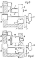
- An angular contact ball bearing 5 ' is preferably used as the rolling bearing, the inner race 11' of which is an integral part of the rotor shaft 1 (FIG. 8).
- the diameter of the inner running surface 11 ' is 0.2 to 0.8 times the diameter of the rotor shaft 1. While in FIG. 1 the rolling bearing is embedded in the bearing bush 50 in an elastic ring 51, the bearing bush 50 is here by means of the Ring 51 resiliently mounted in the carrier 40.
- the free end 11 of the rotor shaft 1 directly adjoining the inner running surface 11 'tapers towards its absolute end 110 and is paraboloid-shaped.
- the ball treads are lubricated by a lubricant reservoir 54 arranged in the bearing bush 50, into which the tapering free end 11 of the rotor shaft 1, or at least its rounded absolute end 110, is immersed and is closely enclosed by the lubricant reservoir 54.
- the inclined surface of the free end 11 favors the supply of lubricant to the ball contact surfaces.
- the passage opening of the bearing bush 50 for the rotor shaft 1 is sealed by a sealing ring 55.
- the axial thrust in the direction of the bearing receiving the free end of the rotor shaft 1 is not generated by setting the axes of the support disks 2 and 3, but by a magnet 71 which is inserted into the bearing bush 50.
- the magnet 71 acts on the free end 11 of the rotor shaft 1 and generates the axial force required for the axial securing of the rotor shaft 1.
- the rotor shaft 1 is reduced in its unsupported length in diameter, so that the spinning rotor 10 is driven at a higher speed without increasing the running speed of the tangential belt. To achieve this, however, it is also sufficient to reduce the shaft diameter only in the area of the drive means.
- a braking device for the rotor shaft 1 is arranged, which is indicated at 9 and will be described with reference to Figure 7.
- the braking device can of course be used in all versions.
- the rotor shaft 1 in the vicinity of the support disk bearing is driven indirectly by a friction roller 8 which is fastened to a sleeve 81 and is rotatably mounted with the latter on an axis 80 arranged on a pivot lever 82.
- the tangential belt 6 runs here over the sleeve 81.
- the rotor shaft 1 is also driven indirectly by the friction roller 8 near the support disks.
- the friction roller 8 is seated in a rotationally fixed manner on the rotor axis of an electric motor 84 flanged to the swivel lever 82 and is set in rotation by the latter.
- the braking device already mentioned in FIG. 4 contains two swivel arms 9 and 90 which can be swiveled about fixed axes 91 and 82.
- Each of the two swivel arms 9 and 90 carries a brake shoe 93 and 94 at the level of the rotor shaft 1.
- a tension spring 95 attached to the swivel arms 9 and 90 brings the brake shoes 93 and 94 into contact with the rotor shaft 1.
- a roller 96 prevented, which is arranged on an arm 97 pivotable about an axis 98 and spreads the pivot arms 9 and 90 apart.
- the rotor shaft can be pulled out of the bearing as before.
- the support disks can be replaced quickly during operation since there are no obstacles in the way of their removal from the bearing block.
- the storage also offers enough space to arrange and design the brake means for the rotor shaft so that the bearings are loaded as little as possible when the spinning rotor is stopped.
Landscapes
- Engineering & Computer Science (AREA)
- Mechanical Engineering (AREA)
- Textile Engineering (AREA)
- Spinning Or Twisting Of Yarns (AREA)
Applications Claiming Priority (2)
| Application Number | Priority Date | Filing Date | Title |
|---|---|---|---|
| DE3346843 | 1983-12-23 | ||
| DE19833346843 DE3346843A1 (de) | 1983-12-23 | 1983-12-23 | Offenend-rotorspinnvorrichtung |
Publications (3)
| Publication Number | Publication Date |
|---|---|
| EP0148468A2 EP0148468A2 (de) | 1985-07-17 |
| EP0148468A3 EP0148468A3 (en) | 1987-03-25 |
| EP0148468B1 true EP0148468B1 (de) | 1990-03-21 |
Family
ID=6217970
Family Applications (1)
| Application Number | Title | Priority Date | Filing Date |
|---|---|---|---|
| EP84115728A Expired - Lifetime EP0148468B1 (de) | 1983-12-23 | 1984-12-18 | Offenend-Rotorspinnvorrichtung |
Country Status (7)
| Country | Link |
|---|---|
| US (1) | US4773210A (en(2012)) |
| EP (1) | EP0148468B1 (en(2012)) |
| JP (1) | JPS60194131A (en(2012)) |
| CS (1) | CS277289B6 (en(2012)) |
| DE (2) | DE3346843A1 (en(2012)) |
| HK (1) | HK11992A (en(2012)) |
| SG (1) | SG101991G (en(2012)) |
Families Citing this family (24)
| Publication number | Priority date | Publication date | Assignee | Title |
|---|---|---|---|---|
| DE3523116A1 (de) * | 1985-06-28 | 1987-01-08 | Schubert & Salzer Maschinen | Offenend-rotorspinnvorrichtung |
| DE3533717A1 (de) * | 1985-09-21 | 1987-03-26 | Stahlecker Fritz | Lagerung und antrieb fuer einen horizontal angeordneten oe-spinnrotor |
| DE3613843C2 (de) * | 1986-04-24 | 1994-12-01 | Stahlecker Fritz | Bremse für einen OE-Spinnrotor |
| CS266602B1 (en) * | 1987-11-19 | 1990-01-12 | Rajsigl Zdenek | Rolling seating for a textile spindle |
| DE3820328C2 (de) * | 1988-06-15 | 1993-12-16 | Stahlecker Gmbh Wilhelm | Bremse für einen OE-Spinnrotor |
| DE3826177C2 (de) * | 1988-08-02 | 1993-10-21 | Rieter Ingolstadt Spinnerei | Offenend-Spinnvorrichtung |
| DE3830181A1 (de) * | 1988-09-06 | 1990-03-15 | Leybold Ag | Gleitlageranordnung fuer eine rasch rotierende welle |
| US5090522A (en) * | 1990-08-24 | 1992-02-25 | Duchossois Industries, Inc. | Brake actuating apparatus |
| US5341631A (en) * | 1991-07-04 | 1994-08-30 | N. V. Bekaert S.A. | Double-twisting device with magnetic device for elevating axial forces |
| DE59304793D1 (de) * | 1992-08-07 | 1997-01-30 | Rieter Ingolstadt Spinnerei | Lagerung für einen Offenend-Spinnrotor |
| DE59300623D1 (de) * | 1992-08-07 | 1995-10-26 | Rieter Ingolstadt Spinnerei | Führung für den Schaft eines Offenend-Spinnrotors. |
| DE4423605B4 (de) * | 1994-07-06 | 2007-05-24 | Rieter Ingolstadt Spinnereimaschinenbau Ag | Lagerung für einen Offenend-Spinnrotor |
| US5622040A (en) * | 1994-12-21 | 1997-04-22 | W. Schlafhorst Ag & Co. | Bearing for an open-end spinning rotor |
| DE19642471B4 (de) * | 1996-10-15 | 2005-05-19 | Saurer Gmbh & Co. Kg | Offenend-Spinnvorrichtung mit einem einzelmotorisch angetriebenen Spinnrotor |
| DE19806723A1 (de) * | 1998-02-18 | 1999-08-19 | Schlafhorst & Co W | Rotorbremse für eine Offenend-Spinnvorrichtung |
| US6983829B2 (en) * | 2001-01-16 | 2006-01-10 | Delphi Technologies, Inc. | Motor actuated park brake for a vehicle |
| DE10130736A1 (de) * | 2001-06-20 | 2003-01-02 | Stahlecker Gmbh Wilhelm | Rotorwelle eines Offenend-Spinnrotors |
| EP1442164A1 (de) * | 2001-10-31 | 2004-08-04 | Holding für Industriebeteiligungen AG | Antrieb für die spinnrotoren einer rotorspinnmaschine |
| US7510058B2 (en) * | 2003-11-25 | 2009-03-31 | Honeywell International Inc. | Electric park brake mechanism and method of operating an electric brake to perform a park brake function |
| DE102009057201A1 (de) * | 2009-11-26 | 2011-06-01 | Spindelfabrik Suessen Gmbh | Offenend-Spinnvorrichtung |
| DE102009057202A1 (de) * | 2009-11-26 | 2011-06-01 | Spindelfabrik Suessen Gmbh | Lagerungseinheit für hohe Drehzahlen |
| JP2014039962A (ja) * | 2010-12-24 | 2014-03-06 | Sintokogio Ltd | ショット処理装置 |
| DE102013106687A1 (de) * | 2013-06-26 | 2014-12-31 | Maschinenfabrik Rieter Ag | Axiallager für einen auf Stützrollen gelagerten Schaft eines Rotors einer Rotorspinnmaschine |
| KR20200133275A (ko) | 2016-08-02 | 2020-11-26 | 생-고뱅 퍼포먼스 플라스틱스 코포레이션 | 베어링 |
Family Cites Families (20)
| Publication number | Priority date | Publication date | Assignee | Title |
|---|---|---|---|---|
| US1338904A (en) * | 1917-12-18 | 1920-05-04 | Chapman Fred Hildreth | Ball-bearing spindle |
| US1763840A (en) * | 1925-06-13 | 1930-06-17 | Burns S Watling | Combined duty and thrust bearing |
| US2173561A (en) * | 1937-09-24 | 1939-09-19 | Clarence T Olson | Take-up device for antifriction bearings |
| GB652714A (en) * | 1948-07-30 | 1951-05-02 | Scragg & Sons | Improvements in and relating to the lower bearings for textile spindles |
| CH347777A (fr) * | 1956-05-11 | 1960-07-15 | Sperry Gyroscope Company Limit | Ensemble constitué par une partie d'un organe rotatif, un pivot et un palier antichocs à billes |
| NL277259A (en(2012)) * | 1961-04-21 | |||
| DE1901453C3 (de) * | 1969-01-13 | 1982-12-02 | Wilhelm Stahlecker Gmbh, 7341 Reichenbach | Lagerung einer Spinnturbine einer Offen-End-Spinnmaschine |
| DE1933929A1 (de) * | 1969-07-04 | 1971-01-14 | Schurr Stahlecker & Grill | Lagerung und Antrieb fuer rotierende Spinnkammern |
| US3750381A (en) * | 1970-07-08 | 1973-08-07 | T M M Rese Ltd | Textile spinning machines |
| DE2061462C3 (de) * | 1970-12-14 | 1980-09-18 | Wilhelm Stahlecker Gmbh, 7341 Reichenbach | Lagerung für Offen-End-Spinnturbinen |
| DE2112913B2 (de) * | 1971-03-17 | 1975-02-27 | Wilhelm Stahlecker Gmbh, 7341 Reichenbach | Lagerung der Spinnturbine eines Offen-End-Spinnaggregates |
| GB1360497A (en) * | 1971-07-28 | 1974-07-17 | Noguera J M | Yarn spinning apparatus |
| GB1410372A (en) * | 1972-02-02 | 1975-10-15 | Noguera J M | Yarn spinning apparatus |
| IT983434B (it) * | 1972-02-10 | 1974-10-31 | Skf Kugellagerfabriken Gmbh | Disposizione di supporto di azio namento per organi di filatura rotanti ad elevate velocita |
| GB1430662A (en) * | 1973-09-21 | 1976-03-31 | Noguera J M | Open end spinning apparatus |
| DE2427055C2 (de) * | 1974-06-05 | 1984-02-16 | Teldix Gmbh, 6900 Heidelberg | OE-Rotorspinneinheit |
| DE2514734C2 (de) * | 1975-04-04 | 1982-10-28 | Stahlecker, Fritz, 7347 Bad Überkingen | Lagerung für einen Offenend-Spinnrotor |
| JPS52137044A (en) * | 1976-05-08 | 1977-11-16 | Toyoda Automatic Loom Works | Rotor shaft supporting device for opennend spinning frames |
| DE2656662A1 (de) * | 1976-12-15 | 1978-06-22 | Schaeffler Ohg Industriewerk | Lagereinheit fuer spindeln von textilmaschinen |
| DE7708087U1 (de) * | 1977-03-16 | 1977-06-30 | Skf Kugellagerfabriken Gmbh, 8720 Schweinfurt | Axialfuehrung fuer den schaft eines auf stuetzrollen gelagerten spinnrotors o.dgl. |
-
1983
- 1983-12-23 DE DE19833346843 patent/DE3346843A1/de active Granted
-
1984
- 1984-12-18 EP EP84115728A patent/EP0148468B1/de not_active Expired - Lifetime
- 1984-12-18 DE DE8484115728T patent/DE3481719D1/de not_active Expired - Lifetime
- 1984-12-19 JP JP59266566A patent/JPS60194131A/ja active Granted
- 1984-12-20 CS CS8410077A patent/CS277289B6/cs unknown
- 1984-12-21 US US06/684,848 patent/US4773210A/en not_active Expired - Fee Related
-
1991
- 1991-12-04 SG SG1019/91A patent/SG101991G/en unknown
-
1992
- 1992-02-13 HK HK119/92A patent/HK11992A/xx unknown
Also Published As
| Publication number | Publication date |
|---|---|
| JPH0153363B2 (en(2012)) | 1989-11-14 |
| SG101991G (en) | 1992-03-20 |
| DE3481719D1 (de) | 1990-04-26 |
| EP0148468A3 (en) | 1987-03-25 |
| EP0148468A2 (de) | 1985-07-17 |
| HK11992A (en) | 1992-02-21 |
| DE3346843C2 (en(2012)) | 1990-05-17 |
| CS1007784A3 (en) | 1992-03-18 |
| JPS60194131A (ja) | 1985-10-02 |
| DE3346843A1 (de) | 1985-07-11 |
| CS277289B6 (en) | 1993-01-13 |
| US4773210A (en) | 1988-09-27 |
Similar Documents
| Publication | Publication Date | Title |
|---|---|---|
| EP0148468B1 (de) | Offenend-Rotorspinnvorrichtung | |
| DE3942612C2 (de) | Offenend-Spinnvorrichtung | |
| DE3533717C2 (en(2012)) | ||
| DE3615777A1 (de) | Stuetzscheibe fuer eine stuetzscheibenlagerung eines oe-spinnrotors | |
| EP1315623B1 (de) | Transportrolle | |
| DE3324129A1 (de) | Lagerung und antrieb fuer einen spinnrotor einer offenend-spinnvorrichtung | |
| EP0583656B1 (de) | Führung für den Schaft eines Offenend-Spinnrotors | |
| DE1939865A1 (de) | Vorrichtung zum Lagern einer Bremsscheibe waehrend der Bearbeitung der Bremsflaechen | |
| EP1101845B1 (de) | Lageranordnung für einen Rotorschaft in einer Offenend-Spinnvorrichtung | |
| DE19756711C2 (de) | Stützscheibenlagerung für einen Offenend-Spinnrotor | |
| AT413047B (de) | Träger für eine fliegende schneiddiskenlagerung | |
| DE3643155A1 (de) | Scheibenbremse des fuehrungsbolzentyps und damit ausgeruestetes kraftfahrzeug | |
| DE69809068T2 (de) | Antriebsrad | |
| AT503064B1 (de) | Offenend-spinnvorrichtung mit einem antreibbaren spinnrotor | |
| DE3904659C2 (en(2012)) | ||
| DE1080002B (de) | Vorrichtung zum Stillsetzen einer Spindel mit Treibriemenantrieb | |
| DE4423605B4 (de) | Lagerung für einen Offenend-Spinnrotor | |
| EP1282790A2 (de) | Spannvorrichtung für zugmittel | |
| DE3709576A1 (de) | Lagerung und antrieb fuer einen spinnrotor | |
| DE2647799C3 (de) | Pelletpresse | |
| DE2707309A1 (de) | Vorrichtung zum stillsetzen des rotors einer offen-end-spinnvorrichtung | |
| DE4325305A1 (de) | Führung für den Schaft eines Offenend-Spinnrotors | |
| DE3523116A1 (de) | Offenend-rotorspinnvorrichtung | |
| DE2144364C3 (de) | Spinn- oder Zwirnspindel | |
| DE19518703A1 (de) | Zahnärztliche Antriebseinheit |
Legal Events
| Date | Code | Title | Description |
|---|---|---|---|
| PUAI | Public reference made under article 153(3) epc to a published international application that has entered the european phase |
Free format text: ORIGINAL CODE: 0009012 |
|
| AK | Designated contracting states |
Designated state(s): CH DE FR GB IT LI |
|
| PUAL | Search report despatched |
Free format text: ORIGINAL CODE: 0009013 |
|
| AK | Designated contracting states |
Kind code of ref document: A3 Designated state(s): CH DE FR GB IT LI |
|
| 17P | Request for examination filed |
Effective date: 19870701 |
|
| 17Q | First examination report despatched |
Effective date: 19880802 |
|
| ITF | It: translation for a ep patent filed | ||
| GRAA | (expected) grant |
Free format text: ORIGINAL CODE: 0009210 |
|
| AK | Designated contracting states |
Kind code of ref document: B1 Designated state(s): CH DE FR GB IT LI |
|
| ET | Fr: translation filed | ||
| REF | Corresponds to: |
Ref document number: 3481719 Country of ref document: DE Date of ref document: 19900426 |
|
| GBT | Gb: translation of ep patent filed (gb section 77(6)(a)/1977) | ||
| ITTA | It: last paid annual fee | ||
| PLBE | No opposition filed within time limit |
Free format text: ORIGINAL CODE: 0009261 |
|
| STAA | Information on the status of an ep patent application or granted ep patent |
Free format text: STATUS: NO OPPOSITION FILED WITHIN TIME LIMIT |
|
| 26N | No opposition filed | ||
| PGFP | Annual fee paid to national office [announced via postgrant information from national office to epo] |
Ref country code: GB Payment date: 19911121 Year of fee payment: 8 |
|
| PGFP | Annual fee paid to national office [announced via postgrant information from national office to epo] |
Ref country code: FR Payment date: 19911127 Year of fee payment: 8 |
|
| PGFP | Annual fee paid to national office [announced via postgrant information from national office to epo] |
Ref country code: CH Payment date: 19920212 Year of fee payment: 8 |
|
| PG25 | Lapsed in a contracting state [announced via postgrant information from national office to epo] |
Ref country code: GB Effective date: 19921218 |
|
| PG25 | Lapsed in a contracting state [announced via postgrant information from national office to epo] |
Ref country code: LI Effective date: 19921231 Ref country code: CH Effective date: 19921231 |
|
| GBPC | Gb: european patent ceased through non-payment of renewal fee |
Effective date: 19921218 |
|
| PG25 | Lapsed in a contracting state [announced via postgrant information from national office to epo] |
Ref country code: FR Effective date: 19930831 |
|
| REG | Reference to a national code |
Ref country code: CH Ref legal event code: PL |
|
| REG | Reference to a national code |
Ref country code: FR Ref legal event code: ST |
|
| PGFP | Annual fee paid to national office [announced via postgrant information from national office to epo] |
Ref country code: DE Payment date: 19950125 Year of fee payment: 11 |
|
| PG25 | Lapsed in a contracting state [announced via postgrant information from national office to epo] |
Ref country code: DE Effective date: 19960903 |