EP0147631A2 - Installation pour mélanger du mortier sec - Google Patents
Installation pour mélanger du mortier sec Download PDFInfo
- Publication number
- EP0147631A2 EP0147631A2 EP84114191A EP84114191A EP0147631A2 EP 0147631 A2 EP0147631 A2 EP 0147631A2 EP 84114191 A EP84114191 A EP 84114191A EP 84114191 A EP84114191 A EP 84114191A EP 0147631 A2 EP0147631 A2 EP 0147631A2
- Authority
- EP
- European Patent Office
- Prior art keywords
- mixing
- shaft
- conveying
- dry mortar
- conveyor
- Prior art date
- Legal status (The legal status is an assumption and is not a legal conclusion. Google has not performed a legal analysis and makes no representation as to the accuracy of the status listed.)
- Granted
Links
Images

Classifications
-
- B—PERFORMING OPERATIONS; TRANSPORTING
- B28—WORKING CEMENT, CLAY, OR STONE
- B28C—PREPARING CLAY; PRODUCING MIXTURES CONTAINING CLAY OR CEMENTITIOUS MATERIAL, e.g. PLASTER
- B28C5/00—Apparatus or methods for producing mixtures of cement with other substances, e.g. slurries, mortars, porous or fibrous compositions
- B28C5/08—Apparatus or methods for producing mixtures of cement with other substances, e.g. slurries, mortars, porous or fibrous compositions using driven mechanical means affecting the mixing
- B28C5/10—Mixing in containers not actuated to effect the mixing
- B28C5/12—Mixing in containers not actuated to effect the mixing with stirrers sweeping through the materials, e.g. with incorporated feeding or discharging means or with oscillating stirrers
- B28C5/1238—Mixing in containers not actuated to effect the mixing with stirrers sweeping through the materials, e.g. with incorporated feeding or discharging means or with oscillating stirrers for materials flowing continuously through the mixing device and with incorporated feeding or discharging devices
- B28C5/1292—Mixing in containers not actuated to effect the mixing with stirrers sweeping through the materials, e.g. with incorporated feeding or discharging means or with oscillating stirrers for materials flowing continuously through the mixing device and with incorporated feeding or discharging devices with rotating stirring and feeding or discharging means fixed on the same axis, e.g. in an inclined container fed at its lower part
-
- B—PERFORMING OPERATIONS; TRANSPORTING
- B01—PHYSICAL OR CHEMICAL PROCESSES OR APPARATUS IN GENERAL
- B01F—MIXING, e.g. DISSOLVING, EMULSIFYING OR DISPERSING
- B01F27/00—Mixers with rotary stirring devices in fixed receptacles; Kneaders
- B01F27/21—Mixers with rotary stirring devices in fixed receptacles; Kneaders characterised by their rotating shafts
- B01F27/2123—Shafts with both stirring means and feeding or discharging means
-
- B—PERFORMING OPERATIONS; TRANSPORTING
- B01—PHYSICAL OR CHEMICAL PROCESSES OR APPARATUS IN GENERAL
- B01F—MIXING, e.g. DISSOLVING, EMULSIFYING OR DISPERSING
- B01F27/00—Mixers with rotary stirring devices in fixed receptacles; Kneaders
- B01F27/60—Mixers with rotary stirring devices in fixed receptacles; Kneaders with stirrers rotating about a horizontal or inclined axis
- B01F27/62—Mixers with rotary stirring devices in fixed receptacles; Kneaders with stirrers rotating about a horizontal or inclined axis comprising liquid feeding, e.g. spraying means
-
- B—PERFORMING OPERATIONS; TRANSPORTING
- B01—PHYSICAL OR CHEMICAL PROCESSES OR APPARATUS IN GENERAL
- B01F—MIXING, e.g. DISSOLVING, EMULSIFYING OR DISPERSING
- B01F27/00—Mixers with rotary stirring devices in fixed receptacles; Kneaders
- B01F27/60—Mixers with rotary stirring devices in fixed receptacles; Kneaders with stirrers rotating about a horizontal or inclined axis
- B01F27/70—Mixers with rotary stirring devices in fixed receptacles; Kneaders with stirrers rotating about a horizontal or inclined axis with paddles, blades or arms
-
- B—PERFORMING OPERATIONS; TRANSPORTING
- B01—PHYSICAL OR CHEMICAL PROCESSES OR APPARATUS IN GENERAL
- B01F—MIXING, e.g. DISSOLVING, EMULSIFYING OR DISPERSING
- B01F35/00—Accessories for mixers; Auxiliary operations or auxiliary devices; Parts or details of general application
- B01F35/71—Feed mechanisms
- B01F35/717—Feed mechanisms characterised by the means for feeding the components to the mixer
- B01F35/71775—Feed mechanisms characterised by the means for feeding the components to the mixer using helical screws
Definitions
- the invention relates to a dry mortar mixing system according to the preamble of claim 1.
- Such dry mortar mixing plants have been known for a long time and include a conveying and a downstream mixing chamber.
- a silo at the front end of the dry mortar mixing system via a vertical nozzle Can be connected as a storage container for the dry mortar, via which the mix flows vertically down into the first feed channel and is transported there via a screw conveyor in a feed pipe to the downstream mixing channel.
- the water can then be added to the mixing channel itself, so that the finished mix can finally be removed in the mixing chamber.
- the conveyor shaft provided with the screw conveyor and the downstream mixer shaft carrying the mixing blades are plugged into one another at the end face via a connecting piece, so that the conveyor and mixing shaft rotate together.
- the object of the invention is therefore to overcome the disadvantages of the prior art and to improve a dry mortar mixing plant of the type mentioned in such a way that the total service life is significantly increased compared to the prior art and, moreover, an easier and faster introduction and Removal of all parts, for example, for cleaning and replacement is guaranteed.
- the object is achieved according to the features specified in the characterizing part of claim 1.
- Advantageous embodiments of the invention are specified in the subclaims.
- the dry mortar mixing plant according to the invention achieves significant advantages over the prior art. Firstly, the total life of the Mischan was many times higher than the prior art, since the described wear and abrasion effects, in particular between the screw conveyor and the surrounding delivery pipe, are avoided by the arrangement according to the invention. This results from the fact that the screw conveyor at the transition from the conveying part to the mixing part is guided at its front end in a bearing additionally arranged there, and the material to be conveyed is no longer fed into the conveying opening via an axial one but in the bottom of the conveying chamber subsequent mixing chamber is dispensed. As a result, the vibrations can be significantly reduced.
- the essential advantage is also achieved that the distance between the outer edge of the screw and the surrounding conveyor tube can be more than 3 mm, preferably 4 to 10 mm and more. This is therefore possible that the conveyor tube no longer has to serve as a centering device to limit the vibrations, so that it is reliably ensured that the outer edge of the screw conveyor no longer strikes the conveyor tube. In particular, this dimension also enables dry discharge without technical problems.
- a common bearing is provided at the front end of the conveyor tube for the mixing shaft and conveyor shaft arranged one behind the other in the axial direction, the coupling according to claim 4 being effected via a coupling hub.
- a simple technical possibility for installing and removing the delivery pipe is provided, which is mounted axially extendable in the outer casing, for which purpose in a further development according to claim 6 at least two axially spaced apart and on the outer casing fixed radial holding devices are provided.
- the simple installation and removal of the delivery pipe also results from the fact that the holding device facing the bearing is provided with a centering flange which comes into contact in a corresponding annular fold of the holding device, but the inner circumference of the holding device is contactless ends in front of the outer casing of the delivery pipe. Therefore, the feed pipe can be easily axially inserted into its installed position in the axial direction, and finally precisely adjusted via its flange.
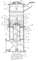
- the bearing 19 further includes a connecting hub 21, in which the front end of the conveyor shaft 11 engages in a corresponding bore 23.
- outlet opening 27 In front of the end 25 of the conveying channel 1 receiving the bearing 19 there is an outlet opening 27 at the bottom for the material to be conveyed and mixed, the outlet opening 27 being arranged between the holding and centering device 7b and the end end 25.
- the mixing shaft 29 is also guided at the end facing the delivery channel 1 in the connecting hub 21 and at the opposite end 35 in a front bearing 37 arranged there. About a before the outlet channel 39 attached to the front end 35, the mix is discharged downwards.
- the mix is fed via the mentioned and not shown silo container to the delivery channel 1 via the attachment flange 5.
- the conveyor shaft 11 is set in rotation via the motor 5, so that the mix is conveyed further via conveyor vanes 41 below the attachment flange 5 into the conveyor tube 9.
- Due to the rotation of the screw conveyor with the delivery pipe 9 arranged in a rotationally fixed manner the material to be mixed is transported further through it and is discharged at its front end in front of the bearing 19 through the lower outlet opening 27 into the subsequent mixing chamber or the mixing channel 3, the lower wall of the mixing channel 3 is arranged lower than the corresponding lower wall of the delivery pipe 9.
- the delivery pipe 9 is installed axially symmetrically to a surrounding outer jacket 43, which at the same time represents the outer wall of the mixing channel 3.
- the conveying channel 1 with the conveying shaft 11 represents a metering device for the uniform feeding of mixed material.
- the mixing shaft 29 is driven via the connecting hub 21 together with the screw conveyor, the material to be mixed being conveyed, if necessary, with the addition of water via the water inlet connector 33 to the front end 35 of the mixing channel 3 and then being discharged via the outlet channel 39.
- short blades 31a are also provided for the further transport of the conveyed material, which are connected to an adjacent one on the mixing shaft 29 seated transport and mixing vanes 31 are attached and encircle the part of the delivery pipe 9 which projects into the mixing channel 3.
- the conveying shaft 11 and the mixing shaft 29 are not only held and guided securely not only at their outer end, but also jointly at their mutually facing end via a common bearing 19. This significantly minimizes the shrinkage of the entire arrangement. Since the conveyor tube 9 thus also no longer has to assume a centering function for the screw conveyor 13 and the conveyor shaft 11, it is possible for the outer edges 45 of the conveyor screw 13 to end at a distance 46 from the inside of the conveyor tube 9. The distance can be more than 3 mm, preferably 4 to 10 mm and, if necessary, even more. A jamming of sand grains and the grains, in particular in the so-called dry discharge between the outer edge 45 and the inside of the conveyor tube 9, is thereby reliably avoided. Furthermore, this ensures a completely uniform metering of the mixture to be supplied, so that the mixture discharged at the outlet 39 always has the same mixing ratio with the water supplied.
- the delivery pipe 9 can also be easily removed if necessary after screws 57 are removed, via which a centering flange 59 welded to the outer circumference of the delivery pipe 9 is firmly connected to the second holding device 7b.
- the holding device 7b ends at a distance from the outer circumference of the delivery pipe 9, so that the delivery pipe 9 can be easily installed or removed in the axial direction from the mixing chamber by this holding device 7b.
- the delivery pipe 9 is centered via the centering flange 59, which comes to rest in an appropriately dimensioned annular fold 61 of the holding device 7b in the installed state.
- the first holding device 7b is merely designed as a pipe socket 63 welded to the inside of the outer jacket 43 for further centering.
- the connecting hub 21 is provided on the end face with at least one radial groove 53, into which corresponding drivers 55 of the mixing shaft 29 or the conveying shaft 11 are inserted by being pushed axially into one another. This ensures the common rotation from the drive unit 15 to the mixing shaft 29.
- the delivery pipe 9 at the end facing the motor 15 is likewise axially essentially non-displaceable in a shaft journal 17 and the mixing shaft 29 is also secured against axial displacement at its opposite end 35 in a manner not shown, no further is required technical measures to prevent that the connecting hub 21 is not axially displaced, since this is automatically and automatically centered by the inserted driver 55 on the conveyor and mixing shaft.
- the outer jacket - as shown in the figure - can also be divided into two, with a split in the area of the holding device 7b. By loosening a quick-release fastener 58, the outer jacket can then be removed in the area of the mixing shaft when the mixing shaft 29 has already been removed lower by a lower swivel bearing 59.
Landscapes
- Chemical & Material Sciences (AREA)
- Chemical Kinetics & Catalysis (AREA)
- Engineering & Computer Science (AREA)
- Mechanical Engineering (AREA)
- Structural Engineering (AREA)
- Screw Conveyors (AREA)
- Disintegrating Or Milling (AREA)
- Soil Conditioners And Soil-Stabilizing Materials (AREA)
- Mixers Of The Rotary Stirring Type (AREA)
- On-Site Construction Work That Accompanies The Preparation And Application Of Concrete (AREA)
- Preparation Of Clay, And Manufacture Of Mixtures Containing Clay Or Cement (AREA)
Priority Applications (1)
| Application Number | Priority Date | Filing Date | Title |
|---|---|---|---|
| AT84114191T ATE45539T1 (de) | 1983-12-23 | 1984-11-23 | Trockenmoertel-mischanlage. |
Applications Claiming Priority (2)
| Application Number | Priority Date | Filing Date | Title |
|---|---|---|---|
| DE3346823 | 1983-12-23 | ||
| DE19833346823 DE3346823A1 (de) | 1983-12-23 | 1983-12-23 | Trockenmoertel-mischanlage |
Publications (3)
| Publication Number | Publication Date |
|---|---|
| EP0147631A2 true EP0147631A2 (fr) | 1985-07-10 |
| EP0147631A3 EP0147631A3 (en) | 1987-05-20 |
| EP0147631B1 EP0147631B1 (fr) | 1989-08-16 |
Family
ID=6217958
Family Applications (1)
| Application Number | Title | Priority Date | Filing Date |
|---|---|---|---|
| EP84114191A Expired EP0147631B1 (fr) | 1983-12-23 | 1984-11-23 | Installation pour mélanger du mortier sec |
Country Status (3)
| Country | Link |
|---|---|
| EP (1) | EP0147631B1 (fr) |
| AT (1) | ATE45539T1 (fr) |
| DE (2) | DE3346823A1 (fr) |
Cited By (14)
| Publication number | Priority date | Publication date | Assignee | Title |
|---|---|---|---|---|
| DE3546501A1 (de) * | 1985-09-13 | 1987-04-23 | Heidelberger Zement Ag | Vorrichtung zur kontinuierlichen bereitstellung von hydraulisch abbindender masse |
| DE3612853A1 (de) * | 1986-04-16 | 1987-11-05 | Bhs Bayerische Berg | Durchlaufmischanlage |
| EP0300342A2 (fr) * | 1987-07-24 | 1989-01-25 | P.F.T. Putz- und Fördertechnik GmbH | Dispositif pour mélanger en continu un mortier avec de l'eau et transporter le mélange au moyen d'une pompe |
| FR2706482A1 (fr) * | 1993-06-18 | 1994-12-23 | Buehler Ag Geb | Fermentateur à orientation couchée, avec un agitateur fixé à un arbre. |
| EP0841137A2 (fr) * | 1996-11-08 | 1998-05-13 | Amann, Markus | Installation et procédé pour la fabrication de matériaux à mélanger, en particulier pour mortier sec |
| EP1688176A3 (fr) * | 2005-02-03 | 2006-08-30 | alsecco GmbH & Co. KG | Dispositif de pompage et de mélange pour des matériaux en poudre et liquides et système pour la production des matériaux pâteuses destinés à la construction |
| ITMO20130181A1 (it) * | 2013-06-24 | 2014-12-25 | Piovan Spa | Apparato di mescolazione per resine |
| CN104890123A (zh) * | 2015-06-19 | 2015-09-09 | 金烜伊 | 一种传送带自动上料均匀出料水泥搅拌机 |
| CN107486944A (zh) * | 2017-09-15 | 2017-12-19 | 南通欧伦嘉机械设备有限公司 | 一种搅拌装置 |
| CN107672023A (zh) * | 2017-10-26 | 2018-02-09 | 黄波 | 一种混凝土砌块成型机 |
| CN109435051A (zh) * | 2019-01-04 | 2019-03-08 | 河北乾昂新型材料科技有限公司 | 一种保温砂浆搅拌系统 |
| CN112717835A (zh) * | 2020-12-16 | 2021-04-30 | 亚洲硅业(青海)股份有限公司 | 氢化反应系统及提高氢化反应转化率的方法 |
| CN114211609A (zh) * | 2021-12-23 | 2022-03-22 | 浙江金州科技有限公司 | 一种用于制备干混砂浆的搅拌机 |
| CN109435051B (zh) * | 2019-01-04 | 2024-05-31 | 河北乾昂新型材料科技有限公司 | 一种保温砂浆搅拌系统 |
Families Citing this family (3)
| Publication number | Priority date | Publication date | Assignee | Title |
|---|---|---|---|---|
| DE9206293U1 (fr) * | 1992-05-11 | 1992-08-20 | Thermozell Entwicklungs- Und Vertriebs Gmbh, Glanegg, At | |
| DE19710067C1 (de) * | 1997-03-12 | 1998-12-03 | Maxit Holding Gmbh | Vorrichtung zum kontinuierlichen Anmachen von Schüttgut- oder Baustoffmischungen |
| DE102006049171B4 (de) * | 2006-10-18 | 2009-01-15 | Werner Dutschmann | Einrichtung zum kontinuierlichen und intensiven Mischen von Trockenmörtel |
Citations (3)
| Publication number | Priority date | Publication date | Assignee | Title |
|---|---|---|---|---|
| US1689963A (en) * | 1926-05-04 | 1928-10-30 | B H Pelton Jr | Concrete mixer and conveyer |
| GB1599856A (en) * | 1978-02-24 | 1981-10-07 | Mathis Fertigputz | Mixing apparatus |
| EP0051224A2 (fr) * | 1980-10-31 | 1982-05-12 | Mathis System-Technik GmbH | Procédé et appareil pour la préparation continue de mortier, enduit ou matériau de construction analogue |
Family Cites Families (3)
| Publication number | Priority date | Publication date | Assignee | Title |
|---|---|---|---|---|
| DE834845C (de) * | 1949-11-01 | 1952-04-15 | Gerhard Sayffaerth Dr | Mischmaschine, insbesondere fuer die Torfveredelung |
| DE7707226U1 (de) * | 1977-03-09 | 1977-06-30 | Mathis Fertigputz Gmbh, 7801 Merdingen | Vorrichtung zur herstellung von angemachtem moertel o.dgl. |
| DE8009428U1 (de) * | 1980-04-05 | 1980-07-24 | Mathis System-Technik Gmbh, 7801 Merdingen | Vorrichtung zur insbesondere kontinuierlichen herstellung von angemachtem moertel o.dgl. |
-
1983
- 1983-12-23 DE DE19833346823 patent/DE3346823A1/de not_active Ceased
-
1984
- 1984-11-23 AT AT84114191T patent/ATE45539T1/de not_active IP Right Cessation
- 1984-11-23 EP EP84114191A patent/EP0147631B1/fr not_active Expired
- 1984-11-23 DE DE8484114191T patent/DE3479410D1/de not_active Expired
Patent Citations (3)
| Publication number | Priority date | Publication date | Assignee | Title |
|---|---|---|---|---|
| US1689963A (en) * | 1926-05-04 | 1928-10-30 | B H Pelton Jr | Concrete mixer and conveyer |
| GB1599856A (en) * | 1978-02-24 | 1981-10-07 | Mathis Fertigputz | Mixing apparatus |
| EP0051224A2 (fr) * | 1980-10-31 | 1982-05-12 | Mathis System-Technik GmbH | Procédé et appareil pour la préparation continue de mortier, enduit ou matériau de construction analogue |
Cited By (19)
| Publication number | Priority date | Publication date | Assignee | Title |
|---|---|---|---|---|
| DE3546501A1 (de) * | 1985-09-13 | 1987-04-23 | Heidelberger Zement Ag | Vorrichtung zur kontinuierlichen bereitstellung von hydraulisch abbindender masse |
| DE3612853A1 (de) * | 1986-04-16 | 1987-11-05 | Bhs Bayerische Berg | Durchlaufmischanlage |
| EP0300342A2 (fr) * | 1987-07-24 | 1989-01-25 | P.F.T. Putz- und Fördertechnik GmbH | Dispositif pour mélanger en continu un mortier avec de l'eau et transporter le mélange au moyen d'une pompe |
| EP0300342A3 (en) * | 1987-07-24 | 1990-11-07 | P.F.T. Putz- Und Fordertechnik Gmbh | Device for continuously mixing mortar with water and for transporting this mixture by pumping |
| FR2706482A1 (fr) * | 1993-06-18 | 1994-12-23 | Buehler Ag Geb | Fermentateur à orientation couchée, avec un agitateur fixé à un arbre. |
| BE1010222A3 (fr) * | 1993-06-18 | 1998-04-07 | Buehler Ag Geb | Fermentateur. |
| EP0841137A2 (fr) * | 1996-11-08 | 1998-05-13 | Amann, Markus | Installation et procédé pour la fabrication de matériaux à mélanger, en particulier pour mortier sec |
| EP0841137A3 (fr) * | 1996-11-08 | 1998-10-21 | Amann, Markus | Installation et procédé pour la fabrication de matériaux à mélanger, en particulier pour mortier sec |
| EP1688176A3 (fr) * | 2005-02-03 | 2006-08-30 | alsecco GmbH & Co. KG | Dispositif de pompage et de mélange pour des matériaux en poudre et liquides et système pour la production des matériaux pâteuses destinés à la construction |
| ITMO20130181A1 (it) * | 2013-06-24 | 2014-12-25 | Piovan Spa | Apparato di mescolazione per resine |
| EP2818290A1 (fr) * | 2013-06-24 | 2014-12-31 | Piovan S.P.A. | Appareil de mélange de résines |
| CN104890123A (zh) * | 2015-06-19 | 2015-09-09 | 金烜伊 | 一种传送带自动上料均匀出料水泥搅拌机 |
| CN107486944A (zh) * | 2017-09-15 | 2017-12-19 | 南通欧伦嘉机械设备有限公司 | 一种搅拌装置 |
| CN107486944B (zh) * | 2017-09-15 | 2020-02-11 | 江苏易明昌建设工程有限公司 | 一种搅拌装置 |
| CN107672023A (zh) * | 2017-10-26 | 2018-02-09 | 黄波 | 一种混凝土砌块成型机 |
| CN109435051A (zh) * | 2019-01-04 | 2019-03-08 | 河北乾昂新型材料科技有限公司 | 一种保温砂浆搅拌系统 |
| CN109435051B (zh) * | 2019-01-04 | 2024-05-31 | 河北乾昂新型材料科技有限公司 | 一种保温砂浆搅拌系统 |
| CN112717835A (zh) * | 2020-12-16 | 2021-04-30 | 亚洲硅业(青海)股份有限公司 | 氢化反应系统及提高氢化反应转化率的方法 |
| CN114211609A (zh) * | 2021-12-23 | 2022-03-22 | 浙江金州科技有限公司 | 一种用于制备干混砂浆的搅拌机 |
Also Published As
| Publication number | Publication date |
|---|---|
| EP0147631B1 (fr) | 1989-08-16 |
| DE3479410D1 (en) | 1989-09-21 |
| DE3346823A1 (de) | 1985-07-11 |
| ATE45539T1 (de) | 1989-09-15 |
| EP0147631A3 (en) | 1987-05-20 |
Similar Documents
| Publication | Publication Date | Title |
|---|---|---|
| EP0147631B1 (fr) | Installation pour mélanger du mortier sec | |
| EP1914056B1 (fr) | Dispositif de mélange continu et intensif de mortier sec | |
| EP2722103A2 (fr) | Malaxeur à mélange forcé avec fonction d'auto-nettoyage et utilisation d'entrées d'air correspondantes | |
| DE2751773A1 (de) | Foerdereinrichtung fuer pulverfoermiges material | |
| EP1055450A2 (fr) | Agitateur | |
| EP0802879A1 (fr) | Dispositif pour doser des produits en vrac | |
| DE3809661A1 (de) | Vorrichtung zum kontinuierlichen mischen eines baustoffs | |
| DE3304129A1 (de) | Verfahren und mischer zum kontinuierlichen beleimen von aus holz-spaenen, -fasern od. dgl. bestehendem mischgut | |
| EP2342060B1 (fr) | Dispositif de dosage | |
| DE2810767A1 (de) | Strahlpumpe | |
| EP0584573A1 (fr) | Dispositif pour la fabrication de mortier apte à être pompé sur le chantier | |
| DE6910964U (de) | Mischvorrichtung | |
| DE3612853C2 (fr) | ||
| DE19542663A1 (de) | Mischvorrichtung | |
| AT399201B (de) | Längsschneidarm für vortriebs- und abbauzwecke u.dgl. | |
| EP0259567B1 (fr) | Dispositif de dosage pour matériel additionnel | |
| DE102005048176B4 (de) | Dosiervorrichtung mit einem Förderkanal und Dosierverfahren | |
| DE102006043596B3 (de) | Fördervorrichtung | |
| DE3013280A1 (de) | Vorrichtung zur insbesondere kontinuierlichen herstellung von angemachtem moertel o.dgl. | |
| DE1913940B1 (de) | Mischvorrichtung | |
| EP0902189A2 (fr) | Pompe d'alimentation | |
| DE2000278A1 (de) | Foerdergeraet fuer pump- und spritzfaehige Betonmischungen | |
| DE491279C (de) | Vorrichtung zum Foerdern von vorgemischtem Moertel, Beton u. dgl. mit Hilfe von Druckluft durch eine Leitung unter Fertigmischen | |
| DE721850C (de) | Einschleusvorrichtung fuer Druckluftfoerderanlagen | |
| EP4338826A1 (fr) | Dispositif et procédé de mélange d'un milieu de gel mou |
Legal Events
| Date | Code | Title | Description |
|---|---|---|---|
| PUAI | Public reference made under article 153(3) epc to a published international application that has entered the european phase |
Free format text: ORIGINAL CODE: 0009012 |
|
| AK | Designated contracting states |
Designated state(s): AT BE CH DE FR GB IT LI LU NL SE |
|
| RAP1 | Party data changed (applicant data changed or rights of an application transferred) |
Owner name: BHS-BAYERISCHE BERG-, HUETTEN- UND SALZWERKE AKTIE |
|
| PUAL | Search report despatched |
Free format text: ORIGINAL CODE: 0009013 |
|
| AK | Designated contracting states |
Kind code of ref document: A3 Designated state(s): AT BE CH DE FR GB IT LI LU NL SE |
|
| 17P | Request for examination filed |
Effective date: 19870926 |
|
| 17Q | First examination report despatched |
Effective date: 19881012 |
|
| GRAA | (expected) grant |
Free format text: ORIGINAL CODE: 0009210 |
|
| AK | Designated contracting states |
Kind code of ref document: B1 Designated state(s): AT BE CH DE FR GB IT LI LU NL SE |
|
| PG25 | Lapsed in a contracting state [announced via postgrant information from national office to epo] |
Ref country code: SE Effective date: 19890816 Ref country code: IT Free format text: LAPSE BECAUSE OF FAILURE TO SUBMIT A TRANSLATION OF THE DESCRIPTION OR TO PAY THE FEE WITHIN THE PRESCRIBED TIME-LIMIT;WARNING: LAPSES OF ITALIAN PATENTS WITH EFFECTIVE DATE BEFORE 2007 MAY HAVE OCCURRED AT ANY TIME BEFORE 2007. THE CORRECT EFFECTIVE DATE MAY BE DIFFERENT FROM THE ONE RECORDED. Effective date: 19890816 Ref country code: GB Effective date: 19890816 Ref country code: FR Free format text: THE PATENT HAS BEEN ANNULLED BY A DECISION OF A NATIONAL AUTHORITY Effective date: 19890816 Ref country code: BE Effective date: 19890816 |
|
| REF | Corresponds to: |
Ref document number: 45539 Country of ref document: AT Date of ref document: 19890915 Kind code of ref document: T |
|
| REF | Corresponds to: |
Ref document number: 3479410 Country of ref document: DE Date of ref document: 19890921 |
|
| PG25 | Lapsed in a contracting state [announced via postgrant information from national office to epo] |
Ref country code: LU Free format text: LAPSE BECAUSE OF NON-PAYMENT OF DUE FEES Effective date: 19891130 |
|
| EN | Fr: translation not filed | ||
| GBV | Gb: ep patent (uk) treated as always having been void in accordance with gb section 77(7)/1977 [no translation filed] | ||
| PLBE | No opposition filed within time limit |
Free format text: ORIGINAL CODE: 0009261 |
|
| STAA | Information on the status of an ep patent application or granted ep patent |
Free format text: STATUS: NO OPPOSITION FILED WITHIN TIME LIMIT |
|
| 26N | No opposition filed | ||
| PGFP | Annual fee paid to national office [announced via postgrant information from national office to epo] |
Ref country code: AT Payment date: 19971009 Year of fee payment: 14 |
|
| PGFP | Annual fee paid to national office [announced via postgrant information from national office to epo] |
Ref country code: CH Payment date: 19971023 Year of fee payment: 14 |
|
| PGFP | Annual fee paid to national office [announced via postgrant information from national office to epo] |
Ref country code: DE Payment date: 19971128 Year of fee payment: 14 |
|
| PGFP | Annual fee paid to national office [announced via postgrant information from national office to epo] |
Ref country code: NL Payment date: 19971130 Year of fee payment: 14 |
|
| PG25 | Lapsed in a contracting state [announced via postgrant information from national office to epo] |
Ref country code: AT Free format text: LAPSE BECAUSE OF NON-PAYMENT OF DUE FEES Effective date: 19981123 |
|
| PG25 | Lapsed in a contracting state [announced via postgrant information from national office to epo] |
Ref country code: LI Free format text: LAPSE BECAUSE OF NON-PAYMENT OF DUE FEES Effective date: 19981130 Ref country code: CH Free format text: LAPSE BECAUSE OF NON-PAYMENT OF DUE FEES Effective date: 19981130 |
|
| PG25 | Lapsed in a contracting state [announced via postgrant information from national office to epo] |
Ref country code: NL Free format text: LAPSE BECAUSE OF NON-PAYMENT OF DUE FEES Effective date: 19990601 |
|
| REG | Reference to a national code |
Ref country code: CH Ref legal event code: PL |
|
| NLV4 | Nl: lapsed or anulled due to non-payment of the annual fee |
Effective date: 19990601 |
|
| PG25 | Lapsed in a contracting state [announced via postgrant information from national office to epo] |
Ref country code: DE Free format text: LAPSE BECAUSE OF NON-PAYMENT OF DUE FEES Effective date: 19990901 |