EP0145331A2 - Drehkopf-Ablenkungsgerät - Google Patents
Drehkopf-Ablenkungsgerät Download PDFInfo
- Publication number
- EP0145331A2 EP0145331A2 EP84307931A EP84307931A EP0145331A2 EP 0145331 A2 EP0145331 A2 EP 0145331A2 EP 84307931 A EP84307931 A EP 84307931A EP 84307931 A EP84307931 A EP 84307931A EP 0145331 A2 EP0145331 A2 EP 0145331A2
- Authority
- EP
- European Patent Office
- Prior art keywords
- rotary
- magnetic heads
- deflection apparatus
- magnets
- movable members
- Prior art date
- Legal status (The legal status is an assumption and is not a legal conclusion. Google has not performed a legal analysis and makes no representation as to the accuracy of the status listed.)
- Withdrawn
Links
Images


Classifications
-
- G—PHYSICS
- G11—INFORMATION STORAGE
- G11B—INFORMATION STORAGE BASED ON RELATIVE MOVEMENT BETWEEN RECORD CARRIER AND TRANSDUCER
- G11B5/00—Recording by magnetisation or demagnetisation of a record carrier; Reproducing by magnetic means; Record carriers therefor
- G11B5/48—Disposition or mounting of heads or head supports relative to record carriers ; arrangements of heads, e.g. for scanning the record carrier to increase the relative speed
- G11B5/58—Disposition or mounting of heads or head supports relative to record carriers ; arrangements of heads, e.g. for scanning the record carrier to increase the relative speed with provision for moving the head for the purpose of maintaining alignment of the head relative to the record carrier during transducing operation, e.g. to compensate for surface irregularities of the latter or for track following
- G11B5/584—Disposition or mounting of heads or head supports relative to record carriers ; arrangements of heads, e.g. for scanning the record carrier to increase the relative speed with provision for moving the head for the purpose of maintaining alignment of the head relative to the record carrier during transducing operation, e.g. to compensate for surface irregularities of the latter or for track following for track following on tapes
- G11B5/588—Disposition or mounting of heads or head supports relative to record carriers ; arrangements of heads, e.g. for scanning the record carrier to increase the relative speed with provision for moving the head for the purpose of maintaining alignment of the head relative to the record carrier during transducing operation, e.g. to compensate for surface irregularities of the latter or for track following for track following on tapes by controlling the position of the rotating heads
Definitions
- This invention relates to a rotary head deflection apparatus which is adapted to displace rotary magnetic heads axially to properly scan the signal tracks recorded on a magnetic tape and is effectively usable for a rotary head type video tape recorder of a helical scan system.
- the system of displacing the rotary magnetic heads as abovementioned is that the magnetic heads are mounted , for example, on a bimorph type piezoelectric element to thereby utilize the electric-to-mechanical characteristic thereof to displace -the magnetic heads.
- the bimorph type piezoelectric element has hysteresis due to the property of material and is insufficient in the mechanical strength.
- the element when intended to be displaced in greater amplitude, involves danger of being broken and moreover the characteristic changes with the lapse of time. Accordingly, it is difficult to construct a rotary head deflection apparatus of durability and stability.
- this system should drive the piezoelectric element by electric signals including the positional change information after the signals are transmitted to a rotary unit, the transmission of signals from the stationary unit to the rotary unit requires electrically conductive slip rings and brushes, thereby having created a problem in that the system becomes complicated in construction. Also, usually high voltage of several hundreds volts is required to displace in the desired pitch the piezoelectric element and a high voltage generating circuit is required for driving the piezoelectric element, whereby the system is defective in a high manufacturing cost.
- the conventional rotary head deflection apparatus such that the magnetic heads are mounted on the bimorph type piezoelectric element, when displaced in greater amplitude, cannot hold the magnetic heads in position perpendicular to the surface of magnetic tape, thereby generating in the magnetic heads the so-called flapping.
- the conventional rotary head deflection apparatus has been defective in that when the magnetic heads. are displaced in greater amplitude, reproducing output voltage attenuates to lead to deterioration of picture quality.
- An object of the invention is to provide a rotary head deflection apparatus which is adapted to vertically displace rotary magnetic heads so as to enable proper scanning on signal tracks recorded on a magnetic tape and which is simple in construction and effectively usable for a helical scan system video tape recorder.
- This rotary head deflection apparatus controls control currents flowing in first and second driving coils disposed at the stationary portion on a concentric circle with the axis of rotation of a rotary member to thereby utilize an electromotive force to enable reliable displacement of magnetic heads mounted on movable members in the direction of the axis of rotation of the rotary member.
- the natural frequency depending on the whole mass of movable members to which the magnetic heads are fixed and the spring constant of an elastic support member for supporting the movable members is set in the vicinity of the basic frequency component of the rotary path, thereby enabling the power necessary for displacing the magnetic heads to be reduced to a minimum.
- the rotary head deflection apparatus of the invention requires no slip rings or brushes, thereby being more advantageous than the conventional apparatus using the slip rings or brushes.
- the rotary head deflection apparatus of the invention can independently control an amount of displacement of each of a pair of magnetic heads in the direction of the axis of rotation, so that each magnetic head can be displaced independently of each other so as to have the optimum rotary path less in vibration and power consumption.
- a rotary head reflection apparatus of high efficiency can be realized.
- the movable members carrying the magnetic heads are supported to the rotary member through two leaf springs fixed to the upper and lower end faces of the movable members, the magnetic heads are displaced always perpendicularly with respect to the surface of magnetic tape, whereby contact pressure of each magnetic head on the tape is kept constant to obtain the stable reproducing output voltage.
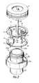
- reference numeral 1 designates a usual rotary drum, on the outer periphery of which a magnetic tape is wound, the rotary drum 1 comprising a rotary body rotated by a motor (not shown) around the axis A of rotation, and 2 and 3 designate magnetic heads, which are mounted on movable members 4 and 5 displaceable in the direction of the axis of rotation and are displaceable in the direction of the same, i.e., in the directions of the arrows of dotted line and solid line.
- Reference numerals 6a, 6b, 7a and 7b designate magnets fixed to the movable members 4 and 5 and magnetized radially with respect to the axis A of rotation, and 10 designates a stationary portion of a rotary cylinder, which constitute in part a stationary drum 10a.
- Reference numeral 9 designates a cylindrical stator, around which first and second driving coils 8a and 8b are wound, the stator 9 being fixed to a stationary portion 10 and positioned to be coaxial with the axis A of rotation, and 11 and 12 designate ring-like-shaped leaf springs used as elastic support members, the movable members 4 and 5 being supported to the rotary member 1 through the leaf springs 11 and 12 in relation of being displaceable only axially of rotary member 1.
- the first and second magnets 6a, 7a, 6b and 7b mounted on the movable members 4 and 5 are disposed to be opposite at the magnetized faces to the first and second driving coils 8a and 8b wound onto the stator 9 and spaced at the predetermined gaps from the coils 8a and 8b respectively.
- Reference numeral 13 designates a rotary shaft supported by bearings 14a and 14b provided at a boss of stationary portion 10, 15a and 15b designate a rotar and a stator of a rotary transformer which properly transfer signals to the magnetic heads 2 and 3, and 16a and 16b designate head position detecting coils for detecting the displacement amount of each magnetic head, the coil faces of coils 16a and 16b being opposite to conductive head base members 17a and 17b keeping the predetermined gaps therefrom respectively.
- This kind of position detection method applies the principle that a high frequency current flows in the head position detection coils 16a and 16b to generate therearound AC magnetic fields, and when the conductive head base members 17a and 17b approach the magnetic fields, and an eddy current is generated at each head base member, so that impedance of the respective head position detecting coils 16a and 16b changes.
- the head position detecting coils 16a and 16b detect the positions of magnetic heads 2 and 3 to thereby position-control the head deflection apparatus under the proper dumping.
- connecting wires from the magnetic heads 2 and 3 to the rotor 15a at the rotary transformer, lead wires from the stator 15b at the same, and lead wires for feeding control currents to the driving coils 8a and 8b, are not shown.
- reference numerals 21a and 21b designate mounting spacers for mounting the leaf springs 11 and 12 onto the rotary body 1
- 22a and 22b designate spring mounting screws for mounting the leaf spring 12 onto the mounting spacers 21a and 21b.
- the spring mounting spacers 21a and 21b and spring mounting screws 22a and 22b mount on the rotary member 1 the leaf springs 11 and 12 carrying the movable members 4 and 5 respectively.
- FIG. 4 the operational principle of the embodiment is shown, in which the components corresponding to those in Figs. 1, 2 and 3 are designated by the same reference numerals and duplicate description is omitted herein.
- reference numerals 30 and 31 designate drive circuits for feeding control currents to the first and second driving coils 8a and 8b respectively
- 32 designates an adder
- 33 designates a subtracter, which are given input commands l A and l B respectively
- 34 and 35 designate the fixed points for mounting the leaf springs 11 and 12 onto the rotary member 1.
- the first magnet 6a and the second magnet 6b mounted on the movable member 4 are of the same N poles at the magnetized faces opposite to the first and second driving coils 8a and 8b
- the first magnet 7 a and the second magnet 7b mounted on the movable member 5 are of N pole and S pole at the magnetized faces opposite to the first and second driving coils 8a and 8b respectively.
- the first magnet 6a and second magnet 6b fixed to the movable member 4 generate the upwardly driving forces respectively, in which the driving forces are represented by f 1 and f 21 the movable member 4 is subjected to the driving force f l + f 2 to move the movable member 4 upwardly.
- the first magnet 7a fixed to the movable member 5 is subjected to the upward driving force f 1 and the second magnet 7b to the downward driving force f 2 , whereby the movable member 5 is subjected to a driving force f l - f 2'
- the first magnet 7a and second magnet 7b fixed to the movable member 5 generate the upward driving forces f l ' and f 2 ' respectively, whereby the movable member 5 is subjected to an upward driving force f 1 ' + f 2 ' as a whole.
- The, first and second driving coils 8a and 8b are given the control currents i 1 and i 2 from the drive circuits 30 and 31.
- the adder 32 and subtracter 33 displace the first and second movable members 4 and 5 corresponding to l A and eB .
- n is the number of turns per unit height of first and second driving coils
- B is magnetic flux generated by the first magnets 6a and 7a and second magnets 6b and 7b, across the magnets and stator 9
- S is the magnet opposite area of the first and second magnets opposite to the first and second driving coils respectively.
- the command input l A can independently control the driving force F A of first movable member 4 and that can similarly control the driving force F B of second movable member 5.
- Reference numeral 40 designates a magnetic tape.
- Fig. 5-(a) shows the first and second driving coils 8a and 8b in condition of giving thereto no control current, in which the gap surface of magnetic head 2 is in contact perpendicularly with the surface of magnetic tape.
- Figs. 5-(b) and -(c) show the displacements of magnetic head 2 when the control currents i 1 and i 2 flow in the first and second driving coils 8a and 8b in the directions of the arrows F respectively.
- the first and second magnets 6a and 6b are subjected to both the downwardly driving forces.
- the composite driving force F acts downwardly to displace the movable member 4 carrying the magnetic heads 2 until the movable member 4 balances with restoring forces of leaf springs 11 and 12 constituting the elastic support member.
- the magnetic head 2 mounted on the movable member 4 is described in Fig. 5, the magnetic head 3 mounted on the movable member 5 is similar to the above.
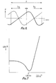
- Fig. 6 is a graph showing the rotary path of magnetic head during, for example, still reproduction, in which the axis of ordinate represents the amount of displacement of magnetic head in the direction of axis of rotation, and the axis of abscissa, the time.
- the rotary path of one magnetic head (to be hereinafter called the A head) is shown by the solid line and that of the other magnetic head (to be hereinafter called the B head) by the dotted line.
- the initial straight line (a time period of T 2) shows the A head in tracking the recorded tracks on the magnetic tape.
- the B head instead of A head is tracking the recorded tracks on the magnetic tape, the A head is restored to the subsequent tracking start position.
- Fig. 7 is a graph of plotting the mean consumptive power P i when the rotary head deflection apparatus of the invention is driven in the rotary path shown in Fig. 6.
- the axis of abscissa represents the natural frequency f 0 of movable member supported to the elastic support member.
- the still reproduction state has been described as the above, but even in other tape speed play states, the basic frequency component of rotary path of magnetic head, is f m [Hz ] as the same as in the still reproduction condition, so that, when the natural frequency f o [Hz] of movable member is set in the vicinity of the rotational speed f m [Hz] of rotary member, the mean consumptive power P i similarly becomes minimum.
Landscapes
- Adjustment Of The Magnetic Head Position Track Following On Tapes (AREA)
Applications Claiming Priority (6)
| Application Number | Priority Date | Filing Date | Title |
|---|---|---|---|
| JP215488/83 | 1983-11-15 | ||
| JP58215488A JPS60107722A (ja) | 1983-11-15 | 1983-11-15 | 回転ヘッド作動装置 |
| JP218911/83 | 1983-11-21 | ||
| JP58218911A JPS60111316A (ja) | 1983-11-21 | 1983-11-21 | 回転ヘッド作動装置 |
| JP224716/83 | 1983-11-29 | ||
| JP58224716A JPS60117410A (ja) | 1983-11-29 | 1983-11-29 | 回転ヘッド作動装置 |
Publications (2)
| Publication Number | Publication Date |
|---|---|
| EP0145331A2 true EP0145331A2 (de) | 1985-06-19 |
| EP0145331A3 EP0145331A3 (de) | 1986-04-23 |
Family
ID=27329763
Family Applications (1)
| Application Number | Title | Priority Date | Filing Date |
|---|---|---|---|
| EP84307931A Withdrawn EP0145331A3 (de) | 1983-11-15 | 1984-11-15 | Drehkopf-Ablenkungsgerät |
Country Status (3)
| Country | Link |
|---|---|
| US (1) | US4695907A (de) |
| EP (1) | EP0145331A3 (de) |
| KR (1) | KR890003199B1 (de) |
Cited By (9)
| Publication number | Priority date | Publication date | Assignee | Title |
|---|---|---|---|---|
| GB2193369A (en) * | 1986-07-16 | 1988-02-03 | Mitsubishi Electric Corp | Rotating drum device |
| GB2209238A (en) * | 1987-08-27 | 1989-05-04 | Mitsubishi Electric Corp | Rotary head deflection apparatus |
| EP0302756A3 (en) * | 1987-08-06 | 1990-04-18 | Mitsubishi Denki Kabushiki Kaisha | Movable rotary head assembly |
| US4970611A (en) * | 1987-08-27 | 1990-11-13 | Mitsubishi Denki Kabushiki Kaisha | Variable tape speed head-carrier drum control apparatus |
| GB2240658A (en) * | 1990-01-12 | 1991-08-07 | Mitsubishi Electric Corp | A rotating magnetic head for a magnetic recording reproduction system |
| EP0441035A1 (de) * | 1990-02-07 | 1991-08-14 | Ampex Systems Corporation | Pantographische Halterung für einen Wandlerkopf |
| EP0503762A3 (en) * | 1991-03-14 | 1993-01-13 | Ampex Corporation | Pantographic mount for a transducer |
| EP0713211A1 (de) * | 1994-11-16 | 1996-05-22 | Sharp Kabushiki Kaisha | Drehkopfartiges magnetisches Aufnahme- oder Wiedergabegerät |
| GB2307774A (en) * | 1995-11-28 | 1997-06-04 | Daewoo Electronics Co Ltd | Track following mechanism for a rotary head drum |
Families Citing this family (8)
| Publication number | Priority date | Publication date | Assignee | Title |
|---|---|---|---|---|
| JP2580655B2 (ja) * | 1987-12-24 | 1997-02-12 | ソニー株式会社 | 回転ヘッド装置 |
| NL8800219A (nl) * | 1988-01-29 | 1989-08-16 | Philips Nv | Roteerbare magneetkopeenheid voor een magneetbandapparaat. |
| WO1990010929A1 (fr) * | 1989-03-06 | 1990-09-20 | Nippon Hoso Kyokai | Appareil d'enregistrement et de reproduction magnetique |
| US5483401A (en) * | 1990-08-08 | 1996-01-09 | Canon Kabushiki Kaisha | Rotary head drum having a connecting member for providing electrical conduction |
| US5343348A (en) * | 1991-04-03 | 1994-08-30 | Victor Company Of Japan, Ltd. | Actuator for displacing a magnetic head |
| JPH0612639A (ja) * | 1992-06-29 | 1994-01-21 | Matsushita Electric Ind Co Ltd | 磁気ヘッド駆動装置 |
| AU1339195A (en) * | 1993-12-15 | 1995-07-03 | Conner Peripherals, Inc | Voice coil driven positioner for coarse and fine positioning of magnetic head in multi-track tape drive |
| JPH1166523A (ja) * | 1997-08-22 | 1999-03-09 | Mitsubishi Electric Corp | 精密回転装置 |
Family Cites Families (10)
| Publication number | Priority date | Publication date | Assignee | Title |
|---|---|---|---|---|
| SU769612A1 (ru) * | 1977-12-05 | 1980-10-07 | Предприятие П/Я А-1705 | Блок вращающихс головок |
| JPS54138413A (en) * | 1978-04-19 | 1979-10-26 | Matsushita Electric Ind Co Ltd | Rotary magnetic head device |
| US4212043A (en) * | 1978-11-01 | 1980-07-08 | Ampex Corporation | Magnetic transducing |
| JPS5563187A (en) * | 1978-11-07 | 1980-05-13 | Nec Corp | Special reproduction device |
| FR2473829B1 (fr) * | 1979-08-21 | 1985-12-27 | Victor Company Of Japan | Appareil magnetique d'enregistrement et de reproduction muni d'un dispositif de reglage des erreurs de suivi de piste de tetes magnetiques rotatives |
| US4337492A (en) * | 1980-04-08 | 1982-06-29 | Minnesota Mining And Manufacturing Company | Head positioning transducer for helical scan video reproducer |
| JPS56165927A (en) * | 1980-05-24 | 1981-12-19 | Sony Corp | Vibration imparting device |
| FR2490048B1 (fr) * | 1980-09-09 | 1986-03-28 | Victor Company Of Japan | Unite de commande de tete video |
| JPS5798130A (en) * | 1980-12-10 | 1982-06-18 | Hitachi Ltd | Inching device for rotating magnetic head |
| JPS5894126A (ja) * | 1981-11-30 | 1983-06-04 | Victor Co Of Japan Ltd | 回転磁気ヘツド装置 |
-
1984
- 1984-11-15 KR KR1019840007166A patent/KR890003199B1/ko not_active Expired
- 1984-11-15 US US06/671,583 patent/US4695907A/en not_active Expired - Lifetime
- 1984-11-15 EP EP84307931A patent/EP0145331A3/de not_active Withdrawn
Cited By (18)
| Publication number | Priority date | Publication date | Assignee | Title |
|---|---|---|---|---|
| GB2193369A (en) * | 1986-07-16 | 1988-02-03 | Mitsubishi Electric Corp | Rotating drum device |
| US4882635A (en) * | 1986-07-16 | 1989-11-21 | Mitsubishi Denki Kabushiki Kaisha | Rotating drum device for a VCR in which the position of the magnetic head is controlled by a magnetic positioning device |
| GB2193369B (en) * | 1986-07-16 | 1990-03-14 | Mitsubishi Electric Corp | Rotating drum device |
| EP0302756A3 (en) * | 1987-08-06 | 1990-04-18 | Mitsubishi Denki Kabushiki Kaisha | Movable rotary head assembly |
| GB2209238A (en) * | 1987-08-27 | 1989-05-04 | Mitsubishi Electric Corp | Rotary head deflection apparatus |
| US4970611A (en) * | 1987-08-27 | 1990-11-13 | Mitsubishi Denki Kabushiki Kaisha | Variable tape speed head-carrier drum control apparatus |
| GB2209238B (en) * | 1987-08-27 | 1991-07-10 | Mitsubishi Electric Corp | Head-carrier drum control apparatus |
| US5313347A (en) * | 1990-01-12 | 1994-05-17 | Mitsubishi Denki Kabushiki Kaisha | Rotating magnetic head for a magnetic recording reproduction system |
| GB2240658B (en) * | 1990-01-12 | 1994-04-06 | Mitsubishi Electric Corp | A rotating magnetic head for a magnetic recording/reproduction system |
| GB2240658A (en) * | 1990-01-12 | 1991-08-07 | Mitsubishi Electric Corp | A rotating magnetic head for a magnetic recording reproduction system |
| EP0441035A1 (de) * | 1990-02-07 | 1991-08-14 | Ampex Systems Corporation | Pantographische Halterung für einen Wandlerkopf |
| EP0503762A3 (en) * | 1991-03-14 | 1993-01-13 | Ampex Corporation | Pantographic mount for a transducer |
| US5227937A (en) * | 1991-03-14 | 1993-07-13 | Ampex Corporation | Side-stiffened flexural pantographic mount for positioning a magnetic transducing head assembly |
| EP0713211A1 (de) * | 1994-11-16 | 1996-05-22 | Sharp Kabushiki Kaisha | Drehkopfartiges magnetisches Aufnahme- oder Wiedergabegerät |
| US5694273A (en) * | 1994-11-16 | 1997-12-02 | Sharp Kabushiki Kaisha | Rotary head type magnetic recording reproducing apparatus |
| US5798894A (en) * | 1994-11-16 | 1998-08-25 | Sharp Kabushiki Kaisha | Rotary head type magnetic recording reproducing apparatus |
| GB2307774A (en) * | 1995-11-28 | 1997-06-04 | Daewoo Electronics Co Ltd | Track following mechanism for a rotary head drum |
| US5798893A (en) * | 1995-11-28 | 1998-08-25 | Daewoo Electronics Co., Ltd. | Head drum assembly for use in a video cassette recorder |
Also Published As
| Publication number | Publication date |
|---|---|
| KR850004162A (ko) | 1985-07-01 |
| KR890003199B1 (ko) | 1989-08-26 |
| US4695907A (en) | 1987-09-22 |
| EP0145331A3 (de) | 1986-04-23 |
Similar Documents
| Publication | Publication Date | Title |
|---|---|---|
| EP0145331A2 (de) | Drehkopf-Ablenkungsgerät | |
| US5418436A (en) | Motor starting method and apparatus | |
| CA1252204A (en) | Positionable transducer mounting structure | |
| CA1252205A (en) | Method and apparatus for producing special motion effects in video recording and reproducing apparatus | |
| US5392176A (en) | Recording/reproducing device employing device housing and printed circuit board and electronics as structural and functional part of media drive motor and the media drive motor | |
| US4692999A (en) | Method of making a multi-coil/multi-magnet actuator | |
| US4160268A (en) | Signal pickup device with tracking control and jitter compensation for a video disc | |
| JPS6346487B2 (de) | ||
| GB1431141A (en) | Linear electromagnetic actuator | |
| US4612592A (en) | Dual coil/dual magnet actuator | |
| US4868432A (en) | Multi-coil actuator with end cap flux carrier | |
| US5223992A (en) | Rotary magnetic head device in magnetic recording and reproducing apparatus | |
| JPH0682451B2 (ja) | 回転磁気ヘツドアツセンブリ | |
| US4590529A (en) | Carriage device for moving and positioning magnetic head | |
| US4916342A (en) | Rotary actuator | |
| JPS6151331B2 (de) | ||
| JPS61246911A (ja) | 回転ヘツド作動装置 | |
| JPS60111316A (ja) | 回転ヘッド作動装置 | |
| JPH058486B2 (de) | ||
| US6498407B1 (en) | Low speed moving magnet motor having a high inertia rotor | |
| GB2212650A (en) | Deflectable transducer head | |
| JPH0123852B2 (de) | ||
| JP3310530B2 (ja) | 回転ヘッド型磁気記録再生装置 | |
| JPS60117410A (ja) | 回転ヘッド作動装置 | |
| JP2529701B2 (ja) | 回転ドラム制御装置 |
Legal Events
| Date | Code | Title | Description |
|---|---|---|---|
| PUAI | Public reference made under article 153(3) epc to a published international application that has entered the european phase |
Free format text: ORIGINAL CODE: 0009012 |
|
| AK | Designated contracting states |
Designated state(s): DE FR GB |
|
| PUAL | Search report despatched |
Free format text: ORIGINAL CODE: 0009013 |
|
| AK | Designated contracting states |
Kind code of ref document: A3 Designated state(s): DE FR GB |
|
| STAA | Information on the status of an ep patent application or granted ep patent |
Free format text: STATUS: THE APPLICATION IS DEEMED TO BE WITHDRAWN |
|
| 18D | Application deemed to be withdrawn |
Effective date: 19861224 |
|
| RIN1 | Information on inventor provided before grant (corrected) |
Inventor name: OKAMOTO, HIROSHI Inventor name: INAJI, TOSHIO Inventor name: YOKOBORI, NOBUYOSHI |