EP0441035A1 - Pantographische Halterung für einen Wandlerkopf - Google Patents
Pantographische Halterung für einen Wandlerkopf Download PDFInfo
- Publication number
- EP0441035A1 EP0441035A1 EP90313391A EP90313391A EP0441035A1 EP 0441035 A1 EP0441035 A1 EP 0441035A1 EP 90313391 A EP90313391 A EP 90313391A EP 90313391 A EP90313391 A EP 90313391A EP 0441035 A1 EP0441035 A1 EP 0441035A1
- Authority
- EP
- European Patent Office
- Prior art keywords
- leaves
- head
- leaf
- rigid
- assembly according
- Prior art date
- Legal status (The legal status is an assumption and is not a legal conclusion. Google has not performed a legal analysis and makes no representation as to the accuracy of the status listed.)
- Withdrawn
Links
- 230000002463 transducing effect Effects 0.000 title claims description 9
- 238000010009 beating Methods 0.000 claims abstract description 4
- 239000000463 material Substances 0.000 claims description 5
- 238000010276 construction Methods 0.000 claims description 2
- 230000003247 decreasing effect Effects 0.000 claims description 2
- 239000007787 solid Substances 0.000 claims 8
- 238000005452 bending Methods 0.000 description 10
- 238000006073 displacement reaction Methods 0.000 description 8
- 230000008901 benefit Effects 0.000 description 6
- 230000000694 effects Effects 0.000 description 5
- 238000000034 method Methods 0.000 description 4
- 230000009471 action Effects 0.000 description 2
- 230000001154 acute effect Effects 0.000 description 2
- 230000007246 mechanism Effects 0.000 description 2
- 230000004044 response Effects 0.000 description 2
- RYGMFSIKBFXOCR-UHFFFAOYSA-N Copper Chemical compound [Cu] RYGMFSIKBFXOCR-UHFFFAOYSA-N 0.000 description 1
- 239000000853 adhesive Substances 0.000 description 1
- 230000001070 adhesive effect Effects 0.000 description 1
- 230000004075 alteration Effects 0.000 description 1
- 229910052782 aluminium Inorganic materials 0.000 description 1
- XAGFODPZIPBFFR-UHFFFAOYSA-N aluminium Chemical compound [Al] XAGFODPZIPBFFR-UHFFFAOYSA-N 0.000 description 1
- 230000000712 assembly Effects 0.000 description 1
- 238000000429 assembly Methods 0.000 description 1
- 230000008859 change Effects 0.000 description 1
- 238000004140 cleaning Methods 0.000 description 1
- 150000001875 compounds Chemical group 0.000 description 1
- 229910052802 copper Inorganic materials 0.000 description 1
- 239000010949 copper Substances 0.000 description 1
- 238000012937 correction Methods 0.000 description 1
- 230000002349 favourable effect Effects 0.000 description 1
- 230000003760 hair shine Effects 0.000 description 1
- 238000005304 joining Methods 0.000 description 1
- 239000000696 magnetic material Substances 0.000 description 1
- 238000004519 manufacturing process Methods 0.000 description 1
- 229910052751 metal Inorganic materials 0.000 description 1
- 239000002184 metal Substances 0.000 description 1
- 230000010363 phase shift Effects 0.000 description 1
- 229910001220 stainless steel Inorganic materials 0.000 description 1
- 239000010935 stainless steel Substances 0.000 description 1
- 238000003466 welding Methods 0.000 description 1
Images

Classifications
-
- G—PHYSICS
- G11—INFORMATION STORAGE
- G11B—INFORMATION STORAGE BASED ON RELATIVE MOVEMENT BETWEEN RECORD CARRIER AND TRANSDUCER
- G11B17/00—Guiding record carriers not specifically of filamentary or web form, or of supports therefor
- G11B17/02—Details
-
- G—PHYSICS
- G11—INFORMATION STORAGE
- G11B—INFORMATION STORAGE BASED ON RELATIVE MOVEMENT BETWEEN RECORD CARRIER AND TRANSDUCER
- G11B5/00—Recording by magnetisation or demagnetisation of a record carrier; Reproducing by magnetic means; Record carriers therefor
- G11B5/48—Disposition or mounting of heads or head supports relative to record carriers ; arrangements of heads, e.g. for scanning the record carrier to increase the relative speed
- G11B5/58—Disposition or mounting of heads or head supports relative to record carriers ; arrangements of heads, e.g. for scanning the record carrier to increase the relative speed with provision for moving the head for the purpose of maintaining alignment of the head relative to the record carrier during transducing operation, e.g. to compensate for surface irregularities of the latter or for track following
- G11B5/584—Disposition or mounting of heads or head supports relative to record carriers ; arrangements of heads, e.g. for scanning the record carrier to increase the relative speed with provision for moving the head for the purpose of maintaining alignment of the head relative to the record carrier during transducing operation, e.g. to compensate for surface irregularities of the latter or for track following for track following on tapes
- G11B5/588—Disposition or mounting of heads or head supports relative to record carriers ; arrangements of heads, e.g. for scanning the record carrier to increase the relative speed with provision for moving the head for the purpose of maintaining alignment of the head relative to the record carrier during transducing operation, e.g. to compensate for surface irregularities of the latter or for track following for track following on tapes by controlling the position of the rotating heads
-
- G—PHYSICS
- G11—INFORMATION STORAGE
- G11B—INFORMATION STORAGE BASED ON RELATIVE MOVEMENT BETWEEN RECORD CARRIER AND TRANSDUCER
- G11B5/00—Recording by magnetisation or demagnetisation of a record carrier; Reproducing by magnetic means; Record carriers therefor
- G11B5/48—Disposition or mounting of heads or head supports relative to record carriers ; arrangements of heads, e.g. for scanning the record carrier to increase the relative speed
- G11B5/52—Disposition or mounting of heads or head supports relative to record carriers ; arrangements of heads, e.g. for scanning the record carrier to increase the relative speed with simultaneous movement of head and record carrier, e.g. rotation of head
- G11B5/53—Disposition or mounting of heads on rotating support
Definitions
- This invention relates to assemblies for mounting transducing heads and particularly to mounts for moving a magnetic head transversely across a magnetic tape track.
- the tape In the conventional "helical-scan" technique of writing and reading television signals on a tape, the tape is moved longitudinally in a helical path around a rotating drum that carries one or more transducing heads for scanning tracks that cross the tape diagonally at an acute angle to the tape length, the angle being determined as a compound function (vector resultant) of the longitudinally-directed tape velocity and the obliquely directed head speed. If, during the reading or reproducing mode, the tape is slowed down to provide a "slow-motion” effect, or speeded up to provide a "fast-motion” effect, or stopped to provide a "stop-motion” or “still-frame” effect, the head still scans the tape obliquely, but at a slightly offset angle to the tape tracks.
- the head To cause the head to follow a previously-recorded track under such circumstances, it has been usual to mount the head on the end of an arm that deflects under magnetic or electric influence, or that bends transversely to the plane of the drum, and to derive a signal from the continuously reading head to indicate its lateral position with respect to the track being read.
- the signal may indicate that the head is either properly in register with the track, or is off-center. This signal is used to control the deflection of the arm to keep the head centered on the track.
- this system is also useful in correcting for undesirable wandering of the head relative to the track as a result of differences in recording-reproducing machines or operational variations in the tape speed, or as the result of shrinking or extension of the tape length due to temperature or humidity changes between the times and places of recording and reproducing.
- the structure disclosed in the aforementioned patent application employs a leaf member which is extremely stiff throughout the greater part of its length, and flexible only in a limited zone adjacent to its bending-pivoting anchorage at the base member to which it was attached.
- This arrangement provides a substantial increase in the range or width of the band of operating frequencies, and improves the "jump speed" of the automatic-scan-tracking apparaus - that is, the ability of the head to leave the end of a track at one end of the tape and to jump back to the correct lateral position for approaching the other tape edge and for picking up the beginning of the same track or the next, depending on whether the tape is stopped or is moving in normal, slow or fast motion mode.
- the track itself is wrapped in a helical path around slightly more than 180 degrees of the drum circumference, and two heads are used, each of which scans the tape for 180 degrees of its circuit and then moves free of the tape for the next 180 degrees while the other head is scanning.
- the head on its arm must make the so-called lateral "jump" to correct for any mis-alignment caused by a change in speed or physical dimensions of the tape.
- pantographic structure The primary benefit of an ideal pantographic structure is to maintain the head perpendicular to the tape at all deflections.
- a head deflection sensing means can be mounted on the head-carrying portion of the pantograph, and at a convenient shorter radius, while maintaining the ratio of head-deflection to sensing-means deflection at a value of unity, so as to achieve an optimum signal-to-noise ratio. Examples of known structures are described in US-A-4337492, US-A-4099211 and US-A-4212043.
- such concentration of stresses may be tolerable.
- concentration of repeated bending stresses would engender the danger of early failure, for the arms would have to be made extremely thin in order to increase the resonant frequencies of the arms to values above the zone in which they might cause instability in the operation of a head-position servo mechanism.
- repeated flexings at concentrated points would contribute to much shorter fatigue life.
- each arm can be flexed in an S-shaped curve, and the system may be operated at high speed, yet the bending stresses are distributed along the length of the arm, and the arm life is maintained at a much higher value.
- the ensemble in the exacting uses contemplated for the present invention, may be extremely sensitive to torsional deflection and vibration of the arms about their longitudinal axes, which can throw off the tracking of the head both directly and also indirectly, as by affecting the operation of the head-position sensing means that is needed to control and correct the tracking (see for example, the arrangement described in US-A-4363046).
- a final problem with some known pantographic designs is that, when subjected to the high-speed flexures at which the present invention is meant to operate, the two arms have nearly the same resonant frequency, and when such a frequency is reached, the action of each arm tends to exaggerate the action of the other, to produce a "beating" effect which is much more severe than it would be for either arm alone.
- the present invention in its preferred forms aims to improve the accuracy of orientation of the head with respect to the tape, to improve the frequency response and jump speed of a mount which moves a magnetic transducing head transversely across a magnetic tape track, to achieve a servo gain ratio of unity, to improve the resistance of such a mount to torsional deformation, and to avoid the tendency for a beat resonance between the two arms of a pantographic mount; though not all such improvements are necessary features of all embodiments of the invention.
- the invention provides a pantograph mounting assembly for moving a magnetic transducing head across a tape track, comprising: a rigid base portion; a rigid tip portion having a box-like structure and carrying the magnetic head in a normal relationship to a predetermined plane corresponding to the tape; a pair of elongate spring arm leaves each having an inboard end portion thereof solidly mounted on said base portion and an outboard end portion thereof solidly connected with and forming part of the rigid tip portion, said leaves being arranged in parallel so as to constitute a flexible pantograph maintaining said head in said normal relationship notwithstanding deflection of the head in said predetermined plane; and electromagnetic means mounted for acting upon said rigid tip portion to deflect said head while maintaining said normal relationship of said head.
- the rigid tip portion may be characterized by selected width, height and length dimensions which maintain optimum stability of the mount and particularly the spring leaf arms.
- the invention provides a pantographic mount for a transducing head, comprising: a rigid base member, a rigid head-carrying member, and a pair of first and second spring leaves each formed of a material having predetermined flexibility characteristics, said leaves being solidly affixed to said base member at respective first and second locations thereon and to said head-carrying member at respective third and fourth locations thereon, said locations having a parallelogram-defining relationship in that said locations define the vertices of a parallelogram; each of said leaves having a structural configuration that is different from the structural configuration of the other leaf, and the structural configuration of each leaf being selected to cooperate with said flexibility characteristics of the leaf to maintain a parallelogram-defining relationship of said locations to one another when said head-carrying member is deflected under load; and an electromagnetic motor arranged to load and to thereby deflect said head-carrying member reciprocatingly such that the head moves in parallel motion only without changing its orientation.
- a preferred embodiment of the invention comprises a pantographic head mount with a pair of generally parallel flexible arms each solidly based at an inboard end and affixed at an outboard end to a voice-coil-driven rigid structure that carries a magnetic head or multiple head stack and holds it continuously normal to a recording medium while traversing across the medium.
- the ensemble has a structure that resists torsional deformation.
- the two arms are structured to have different resonant frequencies, and beating resonance between the arms during high-speed operation is avoided. However, the structures of the two arms are carefully designed to ensure that they still maintain the head continuously normal to the recording medium.
- the arms have different reticulated structural configurations so as to present incongruent but equal-area cross-sections at various chosen points along the arm lengths.
- the two arms may also be formed with differently shaped transverse corrugations or unlike wavy shapes as viewed from the side.
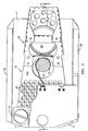
- FIG. 1 a head mounting assembly 10, comprising a base 11 attached to a rotating head drum 12, which rotates about an axis that lies in the plane of the paper (FIGURE 1) to the left of the assembly 10 and extends parallel to the height of the assembly 10.
- the particular structure of the present invention comprises a generally parallel-arm pantographic assembly 14, including an upper flexible arm 14a and a lower flexible arm 14b, the two arms being joined by an intervening web portion 14c integral with arm 14a.
- Arm 14b has an integral extension to the right, forming the bottom plate and nose portion of a rigid head-carrying structure 16 (see below). Both arms 14a and 14b are formed with numerous perforations 91 to decrease the mass of the arm.
- tab portion 14d From the web portion 14c, and integral therewith, extends a tab portion 14d, which is bent orthogonally to the web, parallel to the arm 14b and toward the right, so as to make it possible to join the two arms together solidly as by means of fasteners, adhesives or welds.
- tab portions 14e Also extending to the right from the web 14c are two tab portions 14e, orthogonal to the planes of the arms 14a, 14b and nearly orthogonal to the plane of web 14c.
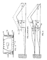
- the tab portions 14e are meant for joining (riveting or welding) the element 14 to the side walls of the rigid head-carrying structure 16 to define therewith a truncated-wedge shaped deflecting assembly 14, 16 (see also FIGURE 2).
- the assembly 14, 16 deflects upwardly and downwardly, as seen in FIGURE 1, from a clamping structure 17 mounting the leftmost end portions 18 of the arms 14a, 14b (FIGURE 1), which are clamped solidly by means of a clamping bolt 19, which is threaded into the base 11.
- the above-described rigid structure 16 is proportioned and formed with a stubby, box-like construction characterized by width, height and length dimensions all in the same general order, so as to maintain optimal torsional stability of the entire mount and particularly of the spring arm leaves that are integrated with the rigid portion 16.
- the rigid portion 16 is strongly cross-braced along all of its three orthogonal planes - length, width and height - and is particularly adapted to help the two flexible spring-arm leaves resist torsional deformation, for the width of the structure at the portion 14c (see FIGURES 2 and 3) is greater than the height at that portion (see FIGURES 1 and 3), and the length of the portion 16 (FIGURES 1 and 2) is hardly more that twice the maximum height dimension.
- the favorable bending characteristics of the pantographic structure including the flexible arms 14a and 14b receive the benefit of enhanced torsional stability from the rigid portion 16.
- the portion 16 maintains the width and spacing of leaves in a rigid relation that substantially eliminates torsional deflections of the leaves 14a and 14b.
- arm 14b to the right to help define the rigid structure 16 is primarily to increase the structural integrity of the apparatus, but in some embodiments of the invention this extension of arm 14b carries further benefits, described more fully below.
- a magnetic transducing head 21 is mounted on the rightmost tip of the rigid portion 16 of the arm structure, and is particularly affixed to the underside of the rightwardly-extending portion of the lower arm 14b, just at the tip point where this extending portion is bent upwardly and to the left to define an acute angle opening toward the left.
- the base 11 has a pair of upstanding side walls 20, across the tops of which is arranged a bridging clamp member 22 (FIGURE 1 only), which is bolted to the head drum 12, together with the base 11, by means of a bolt 23.
- the clamp member 22 supports a head position sensing apparatus 26, which is described in further detail below.
- a voice-coil mechanism 27 which includes a cup-shaped outer pole piece 28 and an inner pole piece 29 assembled with a permanent magnet 30 therebetween; and between the two pole pieces is suspended a hollow cylindrical coil member 31, which extends from the underside of the rigid head mount portion 16.
- Leads 32 extending from the coil 31 carry the operating current used to move the coil 31 and head 21 up or down, depending on the current polarity, for positioning the head transversely of the magnetic track (not shown).
- non-magnetic material such as aluminum or stainless steel (or copper for the coil 31 and leads 32).
- the rigid portion 16 of the head mount has an inner vertical wall containing an aperture 46; and to provide the light source and photocell apparatus that cooperates with the mask and aperture 46, the clamp member 22 is formed with a body portion 55 and with a portion depending therefrom for mounting a light-emitting diode (“LED”) 58, which shines through the aperture 46 from the inboard side as the head and its associated mask and window 46 move up and down.
- LED light-emitting diode
- the LED 58 is supplied with voltage through leads 61 and posts 63, and the currents generated by the photocells 59, 60 are drawn off by leads 62 coupled to conductive posts 64, as by means of a flex-circuit interconnection (not shown).
- the servo circuits that are operated to receive the signals from photocells 59, 60, and to control the position of head 21 through the coil 31 of the voice-coil motor are described in U.S. Patent Application SN-179,161, and form no part of the present invention. It should be clear, however, that such circuits are constrained to operate more precisely by reason of the innovations in the physical structure of the head mount of the present invention.
- the head mount of SN-179,161 comprised a single leaf structure in which the leaf bends essentially about the point in block 11 where the lower arm 14b of the present invention enters block 11.
- the vertical displacement of the aperture 46 was smaller than the vertical displacement of the head 21 (compare dimensions 71, 72 in FIGURE 4), resulting in an other-than-optimum signal-to-noise ratio for the servo system.
- the displacement of the aperture 46 is always substantially the same as the displacement of the head 21 - that is, the displacement ratio between aperture 46 and head 21 is always unity, and the S/N ratio is optimum (compare dimensions 73, 74 in FIGURE 5).
- Another important feature of the present invention is a further application of the principle of altering the structure of the head mount to improve the electronic performance of the head servo system.
- This feature relates to undesired aberrations that appear in the signal from the sensing photocells 59, 60 as a result of resonant harmonic vibrations in the deflecting arm or arms of the mount.
- the higher the frequency of operation the more numerous are the combinations of structural relationships that produce resonance.
- One known method for evading such combinations is to de-regularize the conformation of the structure, and one sub-method of this method is to avoid symmetries during design of the structure.
- one basic symmetry that cannot be done without in a pantographic apparatus is the equi-spacing of the two arms of the mount, at least at the two ends of the arms. If the two pairs of ends are not equi-spaced, then the rigid portion 16 of the mount will alter its inclination to the tape as it traverses the magnetic track, and the ratio of displacements of the head 21 and aperture 46 will depart from unity.
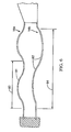
- the present invention contemplates forming the two arms with transverse corrugations 81 and 82 of unlike shape, as shown in FIGURE 6.
- FIGURE 6 Particularly demonstrated in FIGURE 6 are a set of corrugations formed as sine waves, but with the corrugations 81 having a pitch 83 that is different from the pitch 84 of corrugations 82.
- the corrugations 81 having a pitch 83 that is different from the pitch 84 of corrugations 82.
- many other variations would also be suitable, so long as corrugations 81 are different from corrugations 82, either in shape or dimension.
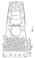
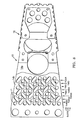
- the two arms 14a and 14b may be formed as shown in FIGURES 7 and 8, to have differently reticulated structural configurations, and to thereby present incongruent but equal-area cross-sections at various chosen points along the arm lengths.
- the arms have incongruent patterns of perforations 91 that are substantially random and asymmetrical about any line or point, and with the pattern for one arm being different from that of the other arm, but nevertheless, both arms having substantially equal cross-sectional areas transverse to the arm length at various given points along the arm length.
- FIGURE 7 the pattern of circular perforations 91 that was shown in FIGURE 2 is varied in the upper arm 14a so that four of the circular perforations in the most outboard row are joined to four of the perforations in the next-inboard row to define four oblong slots.
- the showing of the lower arm 14b is broken away in the Figure so as to show the pattern of 14a more distinctly, because the pattern of 14b is different from that of 14a, as shown in FIGURE 8.
- arm 14b a different four pairs of circular holes 91 in the outboard and next-to-outboard rows are joined to make slots.
- the second and third rows are joined by two slots in each arm; the third and fourth rows by two slots; the fourth and fifth rows by three slots; the fifth and sixth rows by two slots; the sixth and seventh by three slots; the seventh and eighth by three; and the eighth and ninth by three.
- the patterns are different for each pair of rows, the cross-sectional areas of the arms, at any radius of motion of the arms in the general zone of perforations 91, remain equal; and it follows that the qualities of stiffness or flexibility are equal for both arms at any such radius, and the S-shaped or "first-order" bending curves must also remain identical.
- the upper arm 14a could bend more sharply (smaller radius of curvature) near its fixed end, and more gently (greater radius of curvature) near its outboard portion 92, while the other arm 14b bends more sharply near the outboard portion 94 and more gently near the inboard end, so long as both arms translate their outboard portions 92, 94 in the same direction and to the same distance.
- the more sharply bending portions might have smaller cross-sectional areas, and the more gently bending portions might have greater cross-sectional areas; but the end result would be unchanged: the head would be translated but not tilted or pivoted.
- the first and second locations at which the arms 14a and 14b are attached respectively to the base 17, and the third and fourth locations 92 and 94, respectively, have a parallelogram relationship in that these four locations define the vertices of a parallelogram; and when the head-carrying structure 22 is loaded and thereby displaced by the motor means 27-31, a parallelogram relationship of this type is maintained, with the result that the head 21 always remains perpendicular to the magnetic tape.
- perforations 91 one underlying purpose of having perforations 91 is to enable a greater width dimension for the arm without increasing the mass thereof, thus to give the arm a greater resistance to torsional deformations of the type that can be produced by banging or knocking the arm about during head cleaning or adjustment.
- the perforation pattern is made to be asymmetrical, then two further advantages are gained at one stroke: the desired asymmetry is attained by use of the perforations, and also the increased torsional stiffness.
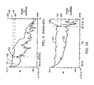
- FIGURES 9 and 10 A comparison of the actual performance of a 10: 1 scale model of the present invention with that of a similarly scaled model of a prior-art type of pantographic structure with stiffened arms, is presented in FIGURES 9 and 10. Both charts begin at about the first resonant frequency, near 10 Hz, at the leftmost point of the abcissa, and extend to the right to about 1000 Hz. These models were constructed at a scale of 10: 1, and it follows that for the actual prototype, having a scale of 1: 1, the frequencies shown on the charts should be translated accordingly, as by multiplying them by a factor of ten.
- the solid line curve in each chart, 101 for FIGURE 9 (prior art), and 102 for FIGURE 10 (present invention), represents the relative amplitude of deflection of the deflecting structure for a given (constant) experimental input, and at the frequencies covered by the chart. This relative amplitude is measured in terms of decibels ("dB") as indicated along the ordinate axis at the left side of the chart, the range covered being between+20.0 and-100 dB.
- the useful range of frequencies for each structure extends to the right as far as the second resonant frequency of the structure, indicated by reference numeral 103 at 227.8 Hz for Figure 9 and by reference numeral 104 at 851.5 Hz for Figure 10.
- the displacement of the leaf arms undergoes an almost instantaneous 180-degree phase shift.
- the input signal has a sinusoidal shape with a pitch or time lapse between peaks that is inversely proportional to the frequency, and the motion of the leaf arms is constantly in phase with this sinusoidal variation: when the signal is increasing on its sinusoidal curve, the deflecting motion of the leaf arms is in a first direction, and when the signal is decreasing on its sinusoidal curve, the arms are deflecting in the opposite direction.
- the present invention multiplies both the useful bandwidth and the upper frequency limit of the electronic system by a factor of nearly four, simply by changing the structure in such a way as to raise its second resonant frequency.
- the structure of the present invention is intended for use in assignee Ampex Corporation's VPR-300 and ACR-225 machines.
Landscapes
- Adjustment Of The Magnetic Head Position Track Following On Tapes (AREA)
- Supporting Of Heads In Record-Carrier Devices (AREA)
Applications Claiming Priority (2)
| Application Number | Priority Date | Filing Date | Title |
|---|---|---|---|
| US477268 | 1990-02-07 | ||
| US07/477,268 US5047883A (en) | 1990-02-07 | 1990-02-07 | Pantograph head mount having double leaves integral with a rigid tip structure |
Publications (1)
| Publication Number | Publication Date |
|---|---|
| EP0441035A1 true EP0441035A1 (de) | 1991-08-14 |
Family
ID=23895232
Family Applications (1)
| Application Number | Title | Priority Date | Filing Date |
|---|---|---|---|
| EP90313391A Withdrawn EP0441035A1 (de) | 1990-02-07 | 1990-12-10 | Pantographische Halterung für einen Wandlerkopf |
Country Status (4)
| Country | Link |
|---|---|
| US (1) | US5047883A (de) |
| EP (1) | EP0441035A1 (de) |
| JP (1) | JPH04214209A (de) |
| KR (1) | KR910015985A (de) |
Cited By (2)
| Publication number | Priority date | Publication date | Assignee | Title |
|---|---|---|---|---|
| EP0503762A3 (en) * | 1991-03-14 | 1993-01-13 | Ampex Corporation | Pantographic mount for a transducer |
| WO1994001862A1 (en) * | 1992-07-01 | 1994-01-20 | Ampex Systems Corporation | Pantographic mount for a magnetic transducing head |
Families Citing this family (15)
| Publication number | Priority date | Publication date | Assignee | Title |
|---|---|---|---|---|
| JP2607756B2 (ja) * | 1990-07-18 | 1997-05-07 | シーゲイト テクノロジー インターナショナル | 磁気ディスクのトラック上でトランスデューサーを位置決めする装置 |
| US5377052A (en) * | 1993-06-14 | 1994-12-27 | International Business Machines Corporation | Actuator assembly for servo-controlled magnetic tape head |
| USH1573H (en) * | 1993-07-01 | 1996-08-06 | Budde; Richard A. | Reduced mass/inertia suspension |
| US6229677B1 (en) | 1993-11-12 | 2001-05-08 | Seagate Technology Llc | Disc drive actuator arm assembly with outer arm z-height less than inner arm z-height |
| US5459921A (en) * | 1993-11-12 | 1995-10-24 | Seagate Technology, Inc. | Method of making a disc drive actuator arm with arm compliance compensation |
| US5521774A (en) * | 1994-03-18 | 1996-05-28 | Cartesian Data, Inc. | Memory storage module for storing and accessing |
| US5508865A (en) * | 1994-05-02 | 1996-04-16 | International Business Machines Corporation | Head guide assembly providing critial alignments and improved resonance response |
| US5726834A (en) * | 1995-06-07 | 1998-03-10 | International Business Machines Corporation | Actuator for servo actuated tape drive |
| US5710681A (en) * | 1995-06-07 | 1998-01-20 | International Business Machines Corporation | Pivot bearing having no moving parts for use in a high density data tape drive |
| US5859105A (en) * | 1997-02-11 | 1999-01-12 | Johnson Matthey, Inc. | Organosilicon-containing compositions capable of rapid curing at low temperature |
| US5793573A (en) * | 1995-06-07 | 1998-08-11 | International Business Machines Corporation | Hybrid actuator servo actuated tape drive having a pivotally mounted motion transmission member |
| US5663854A (en) * | 1995-06-07 | 1997-09-02 | International Business Machines Corporation | Prebent ceramic suspension |
| US5739984A (en) * | 1996-08-28 | 1998-04-14 | International Business Machines Corporation | damping loop for a tape drive actuator with a servo control system |
| US6801405B2 (en) * | 2000-10-25 | 2004-10-05 | Seagate Technology Llc | Unibody (monocoque) arm design for high performance disc drives |
| JP2008262645A (ja) * | 2007-04-13 | 2008-10-30 | Fujifilm Corp | 記録再生装置 |
Citations (3)
| Publication number | Priority date | Publication date | Assignee | Title |
|---|---|---|---|---|
| EP0145331A2 (de) * | 1983-11-15 | 1985-06-19 | Matsushita Electric Industrial Co., Ltd. | Drehkopf-Ablenkungsgerät |
| EP0302756A2 (de) * | 1987-08-06 | 1989-02-08 | Mitsubishi Denki Kabushiki Kaisha | Bewegbare rotierende Kopf-Anordnung |
| GB2212650A (en) * | 1987-12-24 | 1989-07-26 | Sony Corp | Deflectable transducer head |
Family Cites Families (23)
| Publication number | Priority date | Publication date | Assignee | Title |
|---|---|---|---|---|
| US2478223A (en) * | 1946-03-01 | 1949-08-09 | Clarkstan Corp | Electrostrictive translator |
| DE1067232B (de) * | 1957-02-23 | |||
| US3069667A (en) * | 1958-11-26 | 1962-12-18 | Ibm | Transducer apparatus |
| US3931641A (en) * | 1974-08-22 | 1976-01-06 | International Business Machines Corporation | Transducer suspension mount apparatus |
| JPS598891B2 (ja) * | 1974-11-26 | 1984-02-28 | ソニー株式会社 | 回転磁気ヘッド装置 |
| US4203140A (en) * | 1974-11-26 | 1980-05-13 | Sony Corporation | Helical scan VTR with deflectable head |
| US4106065A (en) * | 1976-03-19 | 1978-08-08 | Ampex Corporation | Drive circuitry for controlling movable video head |
| US4151569A (en) * | 1976-03-19 | 1979-04-24 | Ampex Corporation | Positionable transducer mounting structure using a piezoelectric bender element |
| US4099211A (en) * | 1976-09-13 | 1978-07-04 | Ampex Corporation | Positionable transducing mounting structure and driving system therefor |
| JPS5492308A (en) * | 1977-12-29 | 1979-07-21 | Sony Corp | Head tracking device in recorder-reproducer |
| DE2751180C2 (de) * | 1977-11-16 | 1979-11-15 | Grundig E.M.V. Elektro-Mechanische Versuchsanstalt Max Grundig, 8510 Fuerth | Verfahren und Anordnung zur störungsfreien Standbildwiedergabe |
| JPS5923226Y2 (ja) * | 1978-02-10 | 1984-07-11 | ソニー株式会社 | 回転磁気ヘツド装置のヘツド支持装置 |
| US4184183A (en) * | 1978-04-07 | 1980-01-15 | Ampex Corporation | Field replaceable heads for magnetic tape machine |
| US4212043A (en) * | 1978-11-01 | 1980-07-08 | Ampex Corporation | Magnetic transducing |
| GB2050671B (en) * | 1979-06-09 | 1983-08-17 | Sony Corp | Rotary transducer head assemblies |
| NL7907219A (nl) * | 1979-09-28 | 1981-03-31 | Philips Nv | Apparaat voor het opnemen en/of weergeven van op een magneetband in een aantal parallele, longitudinale sporen opgenomen magnetische signalen. |
| US4337492A (en) * | 1980-04-08 | 1982-06-29 | Minnesota Mining And Manufacturing Company | Head positioning transducer for helical scan video reproducer |
| JPS56156924A (en) * | 1980-05-08 | 1981-12-03 | Sony Corp | Track following device |
| JPS56165927A (en) * | 1980-05-24 | 1981-12-19 | Sony Corp | Vibration imparting device |
| JPS6074114A (ja) * | 1983-09-29 | 1985-04-26 | Olympus Optical Co Ltd | ヘツド変位装置 |
| JPS60167173A (ja) * | 1984-02-09 | 1985-08-30 | Nec Corp | ヘツドスライダ加圧支持機構 |
| US4647999A (en) * | 1984-12-03 | 1987-03-03 | Datatape Inc. | Frame for positioning transducing head |
| EP0408659A1 (de) * | 1988-04-08 | 1991-01-23 | Ampex Systems Corporation | Aufstellungsstruktur für magnetwandler |
-
1990
- 1990-02-07 US US07/477,268 patent/US5047883A/en not_active Expired - Lifetime
- 1990-12-10 EP EP90313391A patent/EP0441035A1/de not_active Withdrawn
- 1990-12-20 KR KR1019900021205A patent/KR910015985A/ko not_active Withdrawn
-
1991
- 1991-02-07 JP JP3016674A patent/JPH04214209A/ja active Pending
Patent Citations (3)
| Publication number | Priority date | Publication date | Assignee | Title |
|---|---|---|---|---|
| EP0145331A2 (de) * | 1983-11-15 | 1985-06-19 | Matsushita Electric Industrial Co., Ltd. | Drehkopf-Ablenkungsgerät |
| EP0302756A2 (de) * | 1987-08-06 | 1989-02-08 | Mitsubishi Denki Kabushiki Kaisha | Bewegbare rotierende Kopf-Anordnung |
| GB2212650A (en) * | 1987-12-24 | 1989-07-26 | Sony Corp | Deflectable transducer head |
Non-Patent Citations (1)
| Title |
|---|
| PATENT ABSTRACTS OF JAPAN vol. 12, no. 253 (P-731)(3100) 16 July 1988, & JP-A-63 042017 (MITSUBISHI ELECTRIC CORPORATION) 23 February 1988, * |
Cited By (4)
| Publication number | Priority date | Publication date | Assignee | Title |
|---|---|---|---|---|
| EP0503762A3 (en) * | 1991-03-14 | 1993-01-13 | Ampex Corporation | Pantographic mount for a transducer |
| US5227937A (en) * | 1991-03-14 | 1993-07-13 | Ampex Corporation | Side-stiffened flexural pantographic mount for positioning a magnetic transducing head assembly |
| WO1994001862A1 (en) * | 1992-07-01 | 1994-01-20 | Ampex Systems Corporation | Pantographic mount for a magnetic transducing head |
| US5699211A (en) * | 1992-07-01 | 1997-12-16 | Ampex Corporation | Boxed leaf flexural pantographic mount for a magnetic transducing head assembly |
Also Published As
| Publication number | Publication date |
|---|---|
| KR910015985A (ko) | 1991-09-30 |
| JPH04214209A (ja) | 1992-08-05 |
| US5047883A (en) | 1991-09-10 |
Similar Documents
| Publication | Publication Date | Title |
|---|---|---|
| EP0441035A1 (de) | Pantographische Halterung für einen Wandlerkopf | |
| EP0338698B1 (de) | Trägervorrichtung für einen Wandlerkopf | |
| US5014146A (en) | Magnetic head mounting arm having asymmetrical configuration | |
| US6515834B1 (en) | Side-arm microactuator with piezoelectric adjuster | |
| US4472024A (en) | Apparatus for driving objective lens | |
| US5208703A (en) | Apparatus for supporting optical system | |
| US5949617A (en) | Dynamic-absorber for the suppression of suspension vibrations | |
| US5825590A (en) | Magnetic head suspension mechanism with a thin film thereon for creating a bent portion of a vibration absorbing portion | |
| JPH0729131A (ja) | 低剛性横方向帯たわみ部材を有するヘッド/ジンバル組立体 | |
| US5377052A (en) | Actuator assembly for servo-controlled magnetic tape head | |
| US5894381A (en) | Low mass sectioned load beam of head gimbal assembly having increased high first torsion frequency mode | |
| US4840457A (en) | Angled strut diaphragm spring | |
| US4739430A (en) | Apparatus for positioning a plurality of magnetic heads over preselected tracks of at least two recording disks | |
| CN100416658C (zh) | 具有较低刚度悬挂设计的配置金属框架压电微致动器 | |
| US5339208A (en) | Assembly for supporting a magnetic head to float relative to a magnetic disk | |
| JP2579101B2 (ja) | 磁気変換手段の位置を保持しかつ変化させるための装着体 | |
| JPH07210838A (ja) | 磁気ヘッドサスペンションアセンブリ | |
| JP3806035B2 (ja) | 改善されたロール静的角度調整のための方法および装置 | |
| US5136446A (en) | Apparatus for movably supporting and positioning a transducer | |
| JPH0766644B2 (ja) | ヘツド支持装置 | |
| US5014144A (en) | Magnetic head slider supporting apparatus | |
| WO1998045841A1 (en) | Improved suspension design for a head gimbal assembly | |
| US5764440A (en) | Three flange carriage structure for improved voice coil support | |
| GB2050037A (en) | Signal pickup cartridge for reproducing signals recorded on rotating recording mediums | |
| JPS63144473A (ja) | 浮動型磁気ヘツド装置用サスペンシヨン |
Legal Events
| Date | Code | Title | Description |
|---|---|---|---|
| PUAI | Public reference made under article 153(3) epc to a published international application that has entered the european phase |
Free format text: ORIGINAL CODE: 0009012 |
|
| AK | Designated contracting states |
Kind code of ref document: A1 Designated state(s): DE FR GB NL |
|
| 17P | Request for examination filed |
Effective date: 19911102 |
|
| RAP1 | Party data changed (applicant data changed or rights of an application transferred) |
Owner name: AMPEX SYSTEMS CORPORATION |
|
| 17Q | First examination report despatched |
Effective date: 19940331 |
|
| STAA | Information on the status of an ep patent application or granted ep patent |
Free format text: STATUS: THE APPLICATION HAS BEEN WITHDRAWN |
|
| 18W | Application withdrawn |
Withdrawal date: 19950124 |