EP0302756A2 - Bewegbare rotierende Kopf-Anordnung - Google Patents
Bewegbare rotierende Kopf-Anordnung Download PDFInfo
- Publication number
- EP0302756A2 EP0302756A2 EP88307284A EP88307284A EP0302756A2 EP 0302756 A2 EP0302756 A2 EP 0302756A2 EP 88307284 A EP88307284 A EP 88307284A EP 88307284 A EP88307284 A EP 88307284A EP 0302756 A2 EP0302756 A2 EP 0302756A2
- Authority
- EP
- European Patent Office
- Prior art keywords
- spring plate
- bobbin
- spring
- plate
- yoke assembly
- Prior art date
- Legal status (The legal status is an assumption and is not a legal conclusion. Google has not performed a legal analysis and makes no representation as to the accuracy of the status listed.)
- Granted
Links
Images

Classifications
-
- G—PHYSICS
- G11—INFORMATION STORAGE
- G11B—INFORMATION STORAGE BASED ON RELATIVE MOVEMENT BETWEEN RECORD CARRIER AND TRANSDUCER
- G11B5/00—Recording by magnetisation or demagnetisation of a record carrier; Reproducing by magnetic means; Record carriers therefor
- G11B5/48—Disposition or mounting of heads or head supports relative to record carriers ; arrangements of heads, e.g. for scanning the record carrier to increase the relative speed
- G11B5/58—Disposition or mounting of heads or head supports relative to record carriers ; arrangements of heads, e.g. for scanning the record carrier to increase the relative speed with provision for moving the head for the purpose of maintaining alignment of the head relative to the record carrier during transducing operation, e.g. to compensate for surface irregularities of the latter or for track following
- G11B5/584—Disposition or mounting of heads or head supports relative to record carriers ; arrangements of heads, e.g. for scanning the record carrier to increase the relative speed with provision for moving the head for the purpose of maintaining alignment of the head relative to the record carrier during transducing operation, e.g. to compensate for surface irregularities of the latter or for track following for track following on tapes
- G11B5/588—Disposition or mounting of heads or head supports relative to record carriers ; arrangements of heads, e.g. for scanning the record carrier to increase the relative speed with provision for moving the head for the purpose of maintaining alignment of the head relative to the record carrier during transducing operation, e.g. to compensate for surface irregularities of the latter or for track following for track following on tapes by controlling the position of the rotating heads
Definitions
- This invention relates to an axially deflectable rotary transducer head assembly for a video cassette tape recorder (VCR).
- VCR video cassette tape recorder
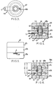
- FIG. 1 designates a rotary shaft
- 2 is a fixed lower drum
- 3 is a rotary upper drum
- 6 are bearings for the shaft
- 7 is an upper transmitter which rotates with the drum 3
- 8 is a lower transmitter mounted on the fixed drum
- 9 is a base block for mounting the upper drum to the shaft
- 13 designates a magnetic tape wrapped obliquely around the outer surfaces of the upper and lower drums.
- a plurality of electrodes 15 mounted to the base block 9 are disposed in sliding engagement with an equal plurality of fixed contacts 14.
- a connector post 16 is electrically coupled to the drive unit 4a through the electrodes 15, a connector 12, and a wiring plate 11.
- the head 5 is electrically connected to the upper transmitter 7 through a connector post 10, the wiring plate 11, and the connector 12.
- reference numeral 41 designates a circular lower spring plate made of a non-magnetic material and having an outwardly extending arm or tab on which the head 5 is mounted
- 43 is a coil bobbin attached to the spring plate 41
- 44 is a deflection control coil wound around the bobbin
- 42 is a circular upper spring plate attached to the bobbin and deformable together with the lower spring plate when the bobbin is linearly driven in a vertical direction
- 45 and 46 are lower and upper, cylindrical, permanent pole magnets extending within the bobbin and having oppositely oriented polarities
- 46a designates a ferromagnetic center pole disposed within the bobbin between the two permanent magnets
- 47 is a yoke assembly constituted by lower, intermediate and upper portions 47a, 47b and 47c.
- a window 49 is provided in the lower portion of the assembly, through which the tab of the lower spring plate extends such that the head 5 fixed to the end thereof is disposed in sliding contact with the tape 13 as shown in Fig. 1.
- the bobbin 43 and coil 44 are disposed for vertical movement in an annular gap defined between the intermediate yoke portion 47b and the magnets 45, 46 and the center pole 46a.
- the outer peripheries of the spring plates 41, 42 are clamped between the yoke assembly portions as shown in Fig. 4.
- a threaded bore 48a in the upper portion 47c accommodates the screw 48 for mounting the yoke assembly 47 to the upper wall 50a of the upper drum recess 50.
- a first closed magnetic circuit is formed by the yoke portions 47a, 47b and the permanent magnet 45 through which a magnetic flux D flows radially outwardly from the center pole 46a in a toroidal path.
- a second closed magnetic circuit is similarly formed by the yoke portions 47b, 47c and the permanent magnet 46 to accommodate a magnetic flux E which flows in a toroidal direction opposite to that of flux D.
- the total flux traversing the coil 44 is thus the sum of the two fluxes D and E.
- automatic tracking compensation may be implemented by applying an appropriate control signal to the coil 44 from a source, not shown, which serves to linearly displace the coil and thus the bobbin, the spring plates 41, 42 and the magnetic head 5 in a vertical direction parallel to the drum shaft 1.
- This invention eliminates the above described thermal expansion problem attendant with the known construction by configuring the upper and lower spring plates such that the lower plate mounting the magnetic head has a substantially larger spring constant than the upper plate.
- the comparatively "softer” and more resilient upper spring plate absorbs or undergoes substantially all of the bending or distortion necessary to accommodate any axial thermal expansion (or contraction) of the coil and bobbin.
- the position of the relatively “stiff" lower spring plate and the magnetic head mounted thereon is thus substantially unaffected by thermally induced bobbin elongations, and the head tracking accuracy and attendantly the reproduced signal fidelity are correspondingly improved.
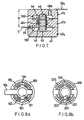
- the lower spring plate 100 is here stamped from a sheet of non-magnetic material having a thickness substantially greater than that of the sheet from which the upper spring plate 200 is stamped (although this is not readily visible in the drawing owing to the small dimensions of the spring plates).
- the axial elongation of the bobbin 43 and coil 44 due to thermal expansion is almost entirely absorbed by the deformation of the upper spring plate 200 due to its much smaller spring constant as compared with that of the thicker lower spring plate 100.
- the lower spring plate undergoes substantially no deformation to accommodate thermal expansions and contractions of the bobbin, and the spacing H of the magnetic head 5 from the wall 50a of the upper drum recess remains substantially constant; it is exclusively varied, in an essentially linear manner, by applying an appropriate control signal to the coil 44 pursuant to automatic tracking compensation.
- the resort to costly bobbin materials having low coefficients of thermal expansion is thus avoided.
- each spring plate 100, 200 includes a central aperture 101, 201 for mounting to the coil bobbin 43, an outer peripheral portion 103, 203 for clamping between the yoke assembly portions, and intermediate portions 102, 202 provided with a plurality of concentric, arcuate slots 105, 205.
- the lower spring plate 100 is provided with an outwardly extending tab 104 to which the magnetic head 5 is fixed. As may be seen by comparing Figs.
- the gaps or spaces 106 between adjacent slot ends in the lower spring plate 100 are wider than the corresponding gaps 206 in the upper spring plate 200, thereby rendering the lower spring plate stiffer than the upper one and imparting a larger spring constant to it.
- the cumulative length of the slots 205 in the upper spring plate may be greater than the overall length of the slots 105 in the lower plate and/or the upper plate slots may be made wider than those of the lower plate.
- the described configurations may be “reversed” such that the upper spring plate is the stiffer one and mounts the magnetic head.
Landscapes
- Adjustment Of The Magnetic Head Position Track Following On Tapes (AREA)
Applications Claiming Priority (2)
| Application Number | Priority Date | Filing Date | Title |
|---|---|---|---|
| JP198468/87 | 1987-08-06 | ||
| JP62198468A JPH0682451B2 (ja) | 1987-08-06 | 1987-08-06 | 回転磁気ヘツドアツセンブリ |
Publications (3)
| Publication Number | Publication Date |
|---|---|
| EP0302756A2 true EP0302756A2 (de) | 1989-02-08 |
| EP0302756A3 EP0302756A3 (en) | 1990-04-18 |
| EP0302756B1 EP0302756B1 (de) | 1992-10-21 |
Family
ID=16391609
Family Applications (1)
| Application Number | Title | Priority Date | Filing Date |
|---|---|---|---|
| EP88307284A Expired EP0302756B1 (de) | 1987-08-06 | 1988-08-05 | Bewegbare rotierende Kopf-Anordnung |
Country Status (4)
| Country | Link |
|---|---|
| US (1) | US4930030A (de) |
| EP (1) | EP0302756B1 (de) |
| JP (1) | JPH0682451B2 (de) |
| DE (1) | DE3875421T2 (de) |
Cited By (2)
| Publication number | Priority date | Publication date | Assignee | Title |
|---|---|---|---|---|
| EP0441035A1 (de) * | 1990-02-07 | 1991-08-14 | Ampex Systems Corporation | Pantographische Halterung für einen Wandlerkopf |
| CN1034033C (zh) * | 1992-01-22 | 1997-02-12 | 夏普公司 | 旋转磁头动态磁迹跟踪装置 |
Families Citing this family (10)
| Publication number | Priority date | Publication date | Assignee | Title |
|---|---|---|---|---|
| JP2840609B2 (ja) * | 1989-11-08 | 1998-12-24 | 日本パイオニクス株式会社 | シート状発熱体 |
| JP2595752B2 (ja) * | 1990-03-27 | 1997-04-02 | 三菱電機株式会社 | 磁気記録再生装置 |
| US5166848A (en) * | 1990-10-03 | 1992-11-24 | Ampex Systems Corporation | Automatic scan tracking mechanism |
| US5343348A (en) * | 1991-04-03 | 1994-08-30 | Victor Company Of Japan, Ltd. | Actuator for displacing a magnetic head |
| US5365390A (en) * | 1991-09-10 | 1994-11-15 | Canon Kabushiki Kaisha | Magnetic head actuator with improved support |
| JP2717494B2 (ja) * | 1992-07-17 | 1998-02-18 | 三菱電機株式会社 | 回転磁気ヘッド装置 |
| TW245792B (de) * | 1993-06-10 | 1995-04-21 | Ibm | |
| JP3046729B2 (ja) * | 1994-11-16 | 2000-05-29 | シャープ株式会社 | 回転ヘッド型磁気記録再生装置 |
| US5798891A (en) * | 1995-07-28 | 1998-08-25 | Daewoo Electronics Co., Ltd | Rotary head drum for a VCR having ring shaped and circular magnets |
| KR0135669Y1 (ko) * | 1995-12-29 | 1999-04-15 | 배순훈 | 브이씨알장치의 헤드드럼 조립체 |
Family Cites Families (5)
| Publication number | Priority date | Publication date | Assignee | Title |
|---|---|---|---|---|
| GB1236765A (en) * | 1968-07-09 | 1971-06-23 | Int Computers Ltd | Improvements in or relating to magnetic head mounting arrangements |
| US4337492A (en) * | 1980-04-08 | 1982-06-29 | Minnesota Mining And Manufacturing Company | Head positioning transducer for helical scan video reproducer |
| JPS56165927A (en) * | 1980-05-24 | 1981-12-19 | Sony Corp | Vibration imparting device |
| JPS5760528A (en) * | 1980-09-30 | 1982-04-12 | Sony Corp | Head supporting in recorder and reproducer |
| EP0145331A3 (de) * | 1983-11-15 | 1986-04-23 | Matsushita Electric Industrial Co., Ltd. | Drehkopf-Ablenkungsgerät |
-
1987
- 1987-08-06 JP JP62198468A patent/JPH0682451B2/ja not_active Expired - Lifetime
-
1988
- 1988-08-05 DE DE8888307284T patent/DE3875421T2/de not_active Expired - Fee Related
- 1988-08-05 EP EP88307284A patent/EP0302756B1/de not_active Expired
- 1988-08-08 US US07/229,410 patent/US4930030A/en not_active Expired - Fee Related
Cited By (2)
| Publication number | Priority date | Publication date | Assignee | Title |
|---|---|---|---|---|
| EP0441035A1 (de) * | 1990-02-07 | 1991-08-14 | Ampex Systems Corporation | Pantographische Halterung für einen Wandlerkopf |
| CN1034033C (zh) * | 1992-01-22 | 1997-02-12 | 夏普公司 | 旋转磁头动态磁迹跟踪装置 |
Also Published As
| Publication number | Publication date |
|---|---|
| JPH0682451B2 (ja) | 1994-10-19 |
| DE3875421T2 (de) | 1993-05-13 |
| DE3875421D1 (de) | 1992-11-26 |
| JPS6442018A (en) | 1989-02-14 |
| EP0302756A3 (en) | 1990-04-18 |
| US4930030A (en) | 1990-05-29 |
| EP0302756B1 (de) | 1992-10-21 |
Similar Documents
| Publication | Publication Date | Title |
|---|---|---|
| CA1252204A (en) | Positionable transducer mounting structure | |
| US4363046A (en) | Deflectable transducer head assembly | |
| EP0302756B1 (de) | Bewegbare rotierende Kopf-Anordnung | |
| GB1579853A (en) | Automatic scan tracking | |
| US5739984A (en) | damping loop for a tape drive actuator with a servo control system | |
| GB2083682A (en) | Video head driving unit | |
| JPS5923226Y2 (ja) | 回転磁気ヘツド装置のヘツド支持装置 | |
| EP0026523B1 (de) | Gerät zum Aufnehmen und/oder Wiedergeben von Information auf einem Magnetband | |
| US5012373A (en) | Apparatus for positioning a magnetic head on a head drum | |
| JP2522019B2 (ja) | 回転ドラム装置 | |
| JP3229432B2 (ja) | 磁気記録再生装置およびその磁気ヘッド駆動方法 | |
| KR0136479Y1 (ko) | 회전 헤드드럼 | |
| JPS626611Y2 (de) | ||
| JP2770724B2 (ja) | 磁気ヘッド駆動装置 | |
| JPH0677281B2 (ja) | 回転ヘッド装置 | |
| KR0154712B1 (ko) | 브이씨알용 회전드럼의 이동헤드 엑츄에이터 장치 | |
| JP2522017B2 (ja) | 回転ドラム装置 | |
| JP2824181B2 (ja) | 回転磁気ヘッド装置 | |
| GB2209237A (en) | Rotary head deflection apparatus | |
| JPH0340210A (ja) | 磁気ヘッド駆動装置 | |
| JPH027218A (ja) | ヘッド駆動素子 | |
| JPH01307011A (ja) | 回転ドラム装置 | |
| JPH06101108B2 (ja) | 回転磁気ヘツド装置 | |
| JPH04132009A (ja) | 磁気記録再生装置 | |
| JPH0461015A (ja) | 回転磁気ヘッドアセンブリ |
Legal Events
| Date | Code | Title | Description |
|---|---|---|---|
| PUAI | Public reference made under article 153(3) epc to a published international application that has entered the european phase |
Free format text: ORIGINAL CODE: 0009012 |
|
| AK | Designated contracting states |
Kind code of ref document: A2 Designated state(s): DE FR GB NL |
|
| PUAL | Search report despatched |
Free format text: ORIGINAL CODE: 0009013 |
|
| AK | Designated contracting states |
Kind code of ref document: A3 Designated state(s): DE FR GB NL |
|
| 17P | Request for examination filed |
Effective date: 19900508 |
|
| 17Q | First examination report despatched |
Effective date: 19911212 |
|
| GRAA | (expected) grant |
Free format text: ORIGINAL CODE: 0009210 |
|
| AK | Designated contracting states |
Kind code of ref document: B1 Designated state(s): DE FR GB NL |
|
| REF | Corresponds to: |
Ref document number: 3875421 Country of ref document: DE Date of ref document: 19921126 |
|
| ET | Fr: translation filed | ||
| REG | Reference to a national code |
Ref country code: GB Ref legal event code: 727 |
|
| REG | Reference to a national code |
Ref country code: GB Ref legal event code: 727 |
|
| REG | Reference to a national code |
Ref country code: GB Ref legal event code: 727B |
|
| REG | Reference to a national code |
Ref country code: GB Ref legal event code: 727B |
|
| REG | Reference to a national code |
Ref country code: GB Ref legal event code: SP |
|
| PLBE | No opposition filed within time limit |
Free format text: ORIGINAL CODE: 0009261 |
|
| STAA | Information on the status of an ep patent application or granted ep patent |
Free format text: STATUS: NO OPPOSITION FILED WITHIN TIME LIMIT |
|
| 26N | No opposition filed | ||
| REG | Reference to a national code |
Ref country code: GB Ref legal event code: 746 Effective date: 20000121 |
|
| REG | Reference to a national code |
Ref country code: FR Ref legal event code: D6 |
|
| PGFP | Annual fee paid to national office [announced via postgrant information from national office to epo] |
Ref country code: DE Payment date: 20010730 Year of fee payment: 14 |
|
| PGFP | Annual fee paid to national office [announced via postgrant information from national office to epo] |
Ref country code: GB Payment date: 20010801 Year of fee payment: 14 |
|
| PGFP | Annual fee paid to national office [announced via postgrant information from national office to epo] |
Ref country code: FR Payment date: 20010810 Year of fee payment: 14 |
|
| PGFP | Annual fee paid to national office [announced via postgrant information from national office to epo] |
Ref country code: NL Payment date: 20010830 Year of fee payment: 14 |
|
| REG | Reference to a national code |
Ref country code: GB Ref legal event code: IF02 |
|
| PG25 | Lapsed in a contracting state [announced via postgrant information from national office to epo] |
Ref country code: GB Free format text: LAPSE BECAUSE OF NON-PAYMENT OF DUE FEES Effective date: 20020805 |
|
| PG25 | Lapsed in a contracting state [announced via postgrant information from national office to epo] |
Ref country code: NL Free format text: LAPSE BECAUSE OF NON-PAYMENT OF DUE FEES Effective date: 20030301 Ref country code: DE Free format text: LAPSE BECAUSE OF NON-PAYMENT OF DUE FEES Effective date: 20030301 |
|
| GBPC | Gb: european patent ceased through non-payment of renewal fee |
Effective date: 20020805 |
|
| PG25 | Lapsed in a contracting state [announced via postgrant information from national office to epo] |
Ref country code: FR Free format text: LAPSE BECAUSE OF NON-PAYMENT OF DUE FEES Effective date: 20030430 |
|
| NLV4 | Nl: lapsed or anulled due to non-payment of the annual fee |
Effective date: 20030301 |
|
| REG | Reference to a national code |
Ref country code: FR Ref legal event code: ST |