EP0145238A2 - Seitlich verstellbare Befestigungsvorrichtung - Google Patents
Seitlich verstellbare Befestigungsvorrichtung Download PDFInfo
- Publication number
- EP0145238A2 EP0145238A2 EP84307566A EP84307566A EP0145238A2 EP 0145238 A2 EP0145238 A2 EP 0145238A2 EP 84307566 A EP84307566 A EP 84307566A EP 84307566 A EP84307566 A EP 84307566A EP 0145238 A2 EP0145238 A2 EP 0145238A2
- Authority
- EP
- European Patent Office
- Prior art keywords
- fastener
- workpiece
- base
- aperture
- weld surface
- Prior art date
- Legal status (The legal status is an assumption and is not a legal conclusion. Google has not performed a legal analysis and makes no representation as to the accuracy of the status listed.)
- Granted
Links
Images
Classifications
-
- B—PERFORMING OPERATIONS; TRANSPORTING
- B29—WORKING OF PLASTICS; WORKING OF SUBSTANCES IN A PLASTIC STATE IN GENERAL
- B29C—SHAPING OR JOINING OF PLASTICS; SHAPING OF MATERIAL IN A PLASTIC STATE, NOT OTHERWISE PROVIDED FOR; AFTER-TREATMENT OF THE SHAPED PRODUCTS, e.g. REPAIRING
- B29C65/00—Joining or sealing of preformed parts, e.g. welding of plastics materials; Apparatus therefor
- B29C65/02—Joining or sealing of preformed parts, e.g. welding of plastics materials; Apparatus therefor by heating, with or without pressure
- B29C65/06—Joining or sealing of preformed parts, e.g. welding of plastics materials; Apparatus therefor by heating, with or without pressure using friction, e.g. spin welding
- B29C65/0672—Spin welding
-
- B—PERFORMING OPERATIONS; TRANSPORTING
- B29—WORKING OF PLASTICS; WORKING OF SUBSTANCES IN A PLASTIC STATE IN GENERAL
- B29C—SHAPING OR JOINING OF PLASTICS; SHAPING OF MATERIAL IN A PLASTIC STATE, NOT OTHERWISE PROVIDED FOR; AFTER-TREATMENT OF THE SHAPED PRODUCTS, e.g. REPAIRING
- B29C65/00—Joining or sealing of preformed parts, e.g. welding of plastics materials; Apparatus therefor
- B29C65/02—Joining or sealing of preformed parts, e.g. welding of plastics materials; Apparatus therefor by heating, with or without pressure
- B29C65/06—Joining or sealing of preformed parts, e.g. welding of plastics materials; Apparatus therefor by heating, with or without pressure using friction, e.g. spin welding
- B29C65/069—Joining or sealing of preformed parts, e.g. welding of plastics materials; Apparatus therefor by heating, with or without pressure using friction, e.g. spin welding the welding tool cooperating with specially formed features of at least one of the parts to be joined, e.g. cooperating with holes or ribs of at least one of the parts to be joined
-
- B—PERFORMING OPERATIONS; TRANSPORTING
- B29—WORKING OF PLASTICS; WORKING OF SUBSTANCES IN A PLASTIC STATE IN GENERAL
- B29C—SHAPING OR JOINING OF PLASTICS; SHAPING OF MATERIAL IN A PLASTIC STATE, NOT OTHERWISE PROVIDED FOR; AFTER-TREATMENT OF THE SHAPED PRODUCTS, e.g. REPAIRING
- B29C66/00—General aspects of processes or apparatus for joining preformed parts
- B29C66/01—General aspects dealing with the joint area or with the area to be joined
- B29C66/05—Particular design of joint configurations
- B29C66/10—Particular design of joint configurations particular design of the joint cross-sections
- B29C66/11—Joint cross-sections comprising a single joint-segment, i.e. one of the parts to be joined comprising a single joint-segment in the joint cross-section
- B29C66/112—Single lapped joints
- B29C66/1122—Single lap to lap joints, i.e. overlap joints
-
- B—PERFORMING OPERATIONS; TRANSPORTING
- B29—WORKING OF PLASTICS; WORKING OF SUBSTANCES IN A PLASTIC STATE IN GENERAL
- B29C—SHAPING OR JOINING OF PLASTICS; SHAPING OF MATERIAL IN A PLASTIC STATE, NOT OTHERWISE PROVIDED FOR; AFTER-TREATMENT OF THE SHAPED PRODUCTS, e.g. REPAIRING
- B29C66/00—General aspects of processes or apparatus for joining preformed parts
- B29C66/01—General aspects dealing with the joint area or with the area to be joined
- B29C66/05—Particular design of joint configurations
- B29C66/302—Particular design of joint configurations the area to be joined comprising melt initiators
- B29C66/3022—Particular design of joint configurations the area to be joined comprising melt initiators said melt initiators being integral with at least one of the parts to be joined
- B29C66/30223—Particular design of joint configurations the area to be joined comprising melt initiators said melt initiators being integral with at least one of the parts to be joined said melt initiators being rib-like
-
- B—PERFORMING OPERATIONS; TRANSPORTING
- B29—WORKING OF PLASTICS; WORKING OF SUBSTANCES IN A PLASTIC STATE IN GENERAL
- B29C—SHAPING OR JOINING OF PLASTICS; SHAPING OF MATERIAL IN A PLASTIC STATE, NOT OTHERWISE PROVIDED FOR; AFTER-TREATMENT OF THE SHAPED PRODUCTS, e.g. REPAIRING
- B29C66/00—General aspects of processes or apparatus for joining preformed parts
- B29C66/40—General aspects of joining substantially flat articles, e.g. plates, sheets or web-like materials; Making flat seams in tubular or hollow articles; Joining single elements to substantially flat surfaces
- B29C66/47—Joining single elements to sheets, plates or other substantially flat surfaces
- B29C66/474—Joining single elements to sheets, plates or other substantially flat surfaces said single elements being substantially non-flat
-
- F—MECHANICAL ENGINEERING; LIGHTING; HEATING; WEAPONS; BLASTING
- F16—ENGINEERING ELEMENTS AND UNITS; GENERAL MEASURES FOR PRODUCING AND MAINTAINING EFFECTIVE FUNCTIONING OF MACHINES OR INSTALLATIONS; THERMAL INSULATION IN GENERAL
- F16B—DEVICES FOR FASTENING OR SECURING CONSTRUCTIONAL ELEMENTS OR MACHINE PARTS TOGETHER, e.g. NAILS, BOLTS, CIRCLIPS, CLAMPS, CLIPS OR WEDGES; JOINTS OR JOINTING
- F16B5/00—Joining sheets or plates, e.g. panels, to one another or to strips or bars parallel to them
- F16B5/06—Joining sheets or plates, e.g. panels, to one another or to strips or bars parallel to them by means of clamps or clips
- F16B5/0607—Joining sheets or plates, e.g. panels, to one another or to strips or bars parallel to them by means of clamps or clips joining sheets or plates to each other
- F16B5/0621—Joining sheets or plates, e.g. panels, to one another or to strips or bars parallel to them by means of clamps or clips joining sheets or plates to each other in parallel relationship
- F16B5/0628—Joining sheets or plates, e.g. panels, to one another or to strips or bars parallel to them by means of clamps or clips joining sheets or plates to each other in parallel relationship allowing for adjustment parallel or perpendicular to the plane of the sheets or plates
-
- B—PERFORMING OPERATIONS; TRANSPORTING
- B29—WORKING OF PLASTICS; WORKING OF SUBSTANCES IN A PLASTIC STATE IN GENERAL
- B29C—SHAPING OR JOINING OF PLASTICS; SHAPING OF MATERIAL IN A PLASTIC STATE, NOT OTHERWISE PROVIDED FOR; AFTER-TREATMENT OF THE SHAPED PRODUCTS, e.g. REPAIRING
- B29C66/00—General aspects of processes or apparatus for joining preformed parts
- B29C66/01—General aspects dealing with the joint area or with the area to be joined
- B29C66/05—Particular design of joint configurations
- B29C66/10—Particular design of joint configurations particular design of the joint cross-sections
- B29C66/11—Joint cross-sections comprising a single joint-segment, i.e. one of the parts to be joined comprising a single joint-segment in the joint cross-section
- B29C66/112—Single lapped joints
-
- B—PERFORMING OPERATIONS; TRANSPORTING
- B29—WORKING OF PLASTICS; WORKING OF SUBSTANCES IN A PLASTIC STATE IN GENERAL
- B29C—SHAPING OR JOINING OF PLASTICS; SHAPING OF MATERIAL IN A PLASTIC STATE, NOT OTHERWISE PROVIDED FOR; AFTER-TREATMENT OF THE SHAPED PRODUCTS, e.g. REPAIRING
- B29C66/00—General aspects of processes or apparatus for joining preformed parts
- B29C66/01—General aspects dealing with the joint area or with the area to be joined
- B29C66/05—Particular design of joint configurations
- B29C66/10—Particular design of joint configurations particular design of the joint cross-sections
- B29C66/13—Single flanged joints; Fin-type joints; Single hem joints; Edge joints; Interpenetrating fingered joints; Other specific particular designs of joint cross-sections not provided for in groups B29C66/11 - B29C66/12
- B29C66/131—Single flanged joints, i.e. one of the parts to be joined being rigid and flanged in the joint area
-
- B—PERFORMING OPERATIONS; TRANSPORTING
- B29—WORKING OF PLASTICS; WORKING OF SUBSTANCES IN A PLASTIC STATE IN GENERAL
- B29L—INDEXING SCHEME ASSOCIATED WITH SUBCLASS B29C, RELATING TO PARTICULAR ARTICLES
- B29L2031/00—Other particular articles
- B29L2031/727—Fastening elements
-
- Y—GENERAL TAGGING OF NEW TECHNOLOGICAL DEVELOPMENTS; GENERAL TAGGING OF CROSS-SECTIONAL TECHNOLOGIES SPANNING OVER SEVERAL SECTIONS OF THE IPC; TECHNICAL SUBJECTS COVERED BY FORMER USPC CROSS-REFERENCE ART COLLECTIONS [XRACs] AND DIGESTS
- Y10—TECHNICAL SUBJECTS COVERED BY FORMER USPC
- Y10S—TECHNICAL SUBJECTS COVERED BY FORMER USPC CROSS-REFERENCE ART COLLECTIONS [XRACs] AND DIGESTS
- Y10S403/00—Joints and connections
- Y10S403/14—Resilient cinch, locking-catch or retainer type
-
- Y—GENERAL TAGGING OF NEW TECHNOLOGICAL DEVELOPMENTS; GENERAL TAGGING OF CROSS-SECTIONAL TECHNOLOGIES SPANNING OVER SEVERAL SECTIONS OF THE IPC; TECHNICAL SUBJECTS COVERED BY FORMER USPC CROSS-REFERENCE ART COLLECTIONS [XRACs] AND DIGESTS
- Y10—TECHNICAL SUBJECTS COVERED BY FORMER USPC
- Y10T—TECHNICAL SUBJECTS COVERED BY FORMER US CLASSIFICATION
- Y10T24/00—Buckles, buttons, clasps, etc.
- Y10T24/30—Trim molding fastener
- Y10T24/309—Plastic type
-
- Y—GENERAL TAGGING OF NEW TECHNOLOGICAL DEVELOPMENTS; GENERAL TAGGING OF CROSS-SECTIONAL TECHNOLOGIES SPANNING OVER SEVERAL SECTIONS OF THE IPC; TECHNICAL SUBJECTS COVERED BY FORMER USPC CROSS-REFERENCE ART COLLECTIONS [XRACs] AND DIGESTS
- Y10—TECHNICAL SUBJECTS COVERED BY FORMER USPC
- Y10T—TECHNICAL SUBJECTS COVERED BY FORMER US CLASSIFICATION
- Y10T24/00—Buckles, buttons, clasps, etc.
- Y10T24/45—Separable-fastener or required component thereof [e.g., projection and cavity to complete interlock]
- Y10T24/45225—Separable-fastener or required component thereof [e.g., projection and cavity to complete interlock] including member having distinct formations and mating member selectively interlocking therewith
- Y10T24/45597—Projection member including noninserted spring for engaging and pushing against receiving member
-
- Y—GENERAL TAGGING OF NEW TECHNOLOGICAL DEVELOPMENTS; GENERAL TAGGING OF CROSS-SECTIONAL TECHNOLOGIES SPANNING OVER SEVERAL SECTIONS OF THE IPC; TECHNICAL SUBJECTS COVERED BY FORMER USPC CROSS-REFERENCE ART COLLECTIONS [XRACs] AND DIGESTS
- Y10—TECHNICAL SUBJECTS COVERED BY FORMER USPC
- Y10T—TECHNICAL SUBJECTS COVERED BY FORMER US CLASSIFICATION
- Y10T24/00—Buckles, buttons, clasps, etc.
- Y10T24/45—Separable-fastener or required component thereof [e.g., projection and cavity to complete interlock]
- Y10T24/45225—Separable-fastener or required component thereof [e.g., projection and cavity to complete interlock] including member having distinct formations and mating member selectively interlocking therewith
- Y10T24/4588—Means for mounting projection or cavity portion
-
- Y—GENERAL TAGGING OF NEW TECHNOLOGICAL DEVELOPMENTS; GENERAL TAGGING OF CROSS-SECTIONAL TECHNOLOGIES SPANNING OVER SEVERAL SECTIONS OF THE IPC; TECHNICAL SUBJECTS COVERED BY FORMER USPC CROSS-REFERENCE ART COLLECTIONS [XRACs] AND DIGESTS
- Y10—TECHNICAL SUBJECTS COVERED BY FORMER USPC
- Y10T—TECHNICAL SUBJECTS COVERED BY FORMER US CLASSIFICATION
- Y10T24/00—Buckles, buttons, clasps, etc.
- Y10T24/45—Separable-fastener or required component thereof [e.g., projection and cavity to complete interlock]
- Y10T24/45225—Separable-fastener or required component thereof [e.g., projection and cavity to complete interlock] including member having distinct formations and mating member selectively interlocking therewith
- Y10T24/4588—Means for mounting projection or cavity portion
- Y10T24/45937—Consisting of thermally fusible substance
-
- Y—GENERAL TAGGING OF NEW TECHNOLOGICAL DEVELOPMENTS; GENERAL TAGGING OF CROSS-SECTIONAL TECHNOLOGIES SPANNING OVER SEVERAL SECTIONS OF THE IPC; TECHNICAL SUBJECTS COVERED BY FORMER USPC CROSS-REFERENCE ART COLLECTIONS [XRACs] AND DIGESTS
- Y10—TECHNICAL SUBJECTS COVERED BY FORMER USPC
- Y10T—TECHNICAL SUBJECTS COVERED BY FORMER US CLASSIFICATION
- Y10T403/00—Joints and connections
- Y10T403/16—Joints and connections with adjunctive protector, broken parts retainer, repair, assembly or disassembly feature
- Y10T403/1616—Position or guide means
-
- Y—GENERAL TAGGING OF NEW TECHNOLOGICAL DEVELOPMENTS; GENERAL TAGGING OF CROSS-SECTIONAL TECHNOLOGIES SPANNING OVER SEVERAL SECTIONS OF THE IPC; TECHNICAL SUBJECTS COVERED BY FORMER USPC CROSS-REFERENCE ART COLLECTIONS [XRACs] AND DIGESTS
- Y10—TECHNICAL SUBJECTS COVERED BY FORMER USPC
- Y10T—TECHNICAL SUBJECTS COVERED BY FORMER US CLASSIFICATION
- Y10T403/00—Joints and connections
- Y10T403/47—Molded joint
- Y10T403/471—And independent connection
Definitions
- the present invention relates to fasteners which are capable of lateral adjustment in the securing of workpieces.
- fasteners will find particular use in the automobile, appliance and like industries. For example, it often happens that a first workpiece (in the form of an article) is to be secured by a plurality of fasteners to a second workpiece (in the form of a plate or panel) which is pre-formed with a plurality of apertures for engagement with respective ones of the fasteners. Consistently exact fastener and aperture alignment is unlikely to occur in practice. However, bodily movement of the article relatively to the apertured panel may not be possible, and in any event may not bring all of the fasteners into exact alignment with all of the apertures. A first aim of the present invention has been to overcome this type of difficulty.
- a fastener capable of lateral adjustment in the securing of workpieces is characterised by comprising a base and a fastening element, said base having a centrally disposed aperture, having a recess in communication with said aperture and having a weld surface of a material that can be fused to a compatible workpiece, said fastening element having a head and having a shank for securement to a second workpiece, said head being floatingly seated in said recess with said shank extending through said aperture, whereby said head can be freely moved within said recess and is captivated thereby both during and after a welding operation in which said weld surface is fused to said compatible workpiece.
- the base of the fastener has a weld surface of a material that can be fused to a compatible workpiece.
- the present invention is particularly pertinent in friction welding, ultrasonic welding and solvent welding.
- solvent welding here includes the straight forward use of an appropriate adhesive.
- Retaining means may be provided for allowing pre-assembly of said element and said base before a welding operation.
- Said retaining means may comprise at least one resilient member extending outwardly from said element and engageable with a portion of said base near said aperture.
- said at least one resilient member comprises a thin flexible resilient annular collar.
- said shank at locations thereof which extend through said aperture may be substantially smaller in maximum lateral dimension than the minimum lateral dimension of said aperture.
- At least one yielding driving tab may be provided adjacent said weld surface, said at least one tab being adapted to be used to rotate said base during a friction welding operation and being adapted to yield when an optimal melt condition- exists between- said weld surface and said compatible workpiece.
- sealing biasing means may be provided in the form of a continuous annular flexible generally frustoconical skirt extending from said base.
- said base is generally annular and has a centrally disposed-gener-ally cylindrical portion
- said weld surface is generally annular and is formed on a flange which extends laterally outwardly from one end of said cylindrical portion, there being an inwardly directed rim having an aperture at the opposite end of said cylindrical portion, and said head of said element being axially and radially smaller than said cylindrical portion and radially larger than said aperture in said rim.
- a second aim, of the present invention has been to tackle the problem that the increased use of polymeric (i.e. plastics) materials has created a need for new ways of accurately connecting such materials to each other as well as to different materials, and in particular has been to tackle the problem of properly positioning any construction of fastener with respect to a workpiece to which the fastener is to be secured by welding.
- polymeric (i.e. plastics) materials has created a need for new ways of accurately connecting such materials to each other as well as to different materials, and in particular has been to tackle the problem of properly positioning any construction of fastener with respect to a workpiece to which the fastener is to be secured by welding.
- a combination of a fastener and a moulded workpiece is characterised by said fastener having a weld surface weldable to said workpiece, said workpiece and said fastener having complementary surface locating means for ensuring that said fastener is positioned at a predetermined location on said workpiece during and after a welding operation.
- the fastener preferably includes the various features of construction discussed hereinbefore.
- Said locating means may comprise at least one surface interruption on said workpiece for resisting lateral movement of said fastener relative to said workpiece, and indeed may comprise a plurality of concentric annular protrusions moulded integrally with said workpiece, and a matching plurality of concentric annular protrusions on said weld surface.
- said locating means comprises at least one annular formation moulded integrally with said workpiece, it may be that at least a portion of said weld surface is generally circular and fits complementarily with said at least one annular formation on said workpiece.
- means are provided for assuring proper positioning of said fastener in a direction generally parallel to the axis of said fastener, said positioning means comprising cross ribs on said workpiece.
- the purpose of said locating means is to provide a rough placement guide.
- the base is welded to the article while the fastening element is captivated within the recess.
- the shape of the locating means is such that welding is prevented between the fastening element and the article. After welding, fine lateral adjustment can be made between the-fastening element and-the aperture panel. The result is an easier assembly operation and simplified moulding of parts.
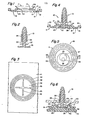
- Figures 1 and 2 show the two parts of the fastener of the present invention in an unassembled condition, the fastener possibly being formed of a plastics material such as a thermoplastics material.
- Base 11 shown in Figure 1 comprises a generally low-profile cylinder 13 with an outwardly directed annular flange 15 at the lower end of the cylinder 13 and an inwardly directed rim 17 at the opposite end of the cylinder 13.
- the flange 15 has a weld surface 19 which includes a series of concentric circular ribs 21.
- the cylinder 13 forms a recess 25 in the base 11, and the recess 25 communicates with an aperture 27 in the rim 17.
- a relatively thin tapering frustoconical skirt 29 extends from the rim 17.
- Fastening element 31 shown in Figure 2 has an elongate shank 33 with a head 35 at one end.
- the element 31 shown has laterally extending prongs 39, but the prongs 39 could be replaced by any of a variety of fastenings including push, snap and resilient self-expanding types.
- a collar 37 projects outwardly from the shank 33 near the head 35.
- Figure 3 shows concentric rings 42 moulded in an article 41.
- the rings 42 protrude from an adjacent surface 43 of the article.
- the rings 42 on the article 41 and the annular ribs 21 on the base 11 are complementary in shape such that the base 11 can be positioned on the article 41 at a specific location.
- the interfitting complementary surface configurations of the ribs 21 and the rings 42 facilitate welding of the base 11 to the article 41.
- Protruding cross ribs 45 form an abutment against which the head 35 can react after attachment of the base 11 to the article 41.
- Figures 4 and 5 show the two-part fastener 10 assembled but unattached to the article 41.
- the head 35 fits loosely within the recess 25 so that the fastening element 31 can be moved laterally relative to the base 11.
- the collar 37 is snappingly engaged by the rim 17 as the shank 33 and the collar 37 are inserted, from below as shown in Figure 4, through the aperture 27 in the rim 17.
- Either the collar 37 or the inner portion of the rim 17_ or both may be resiliently flexible to achieve the engaging relationship between the two parts of the fastener 10. Once assembled the fastener is ready to be attached.
- the base 11 has driving tabs 22 formed at the outer edge 23 thereof. The tabs 22 are used to spin the base and achieve a friction weld between the base and the article 41.
- the tabs 22 are located adjacent to the weld surface 19 so that, when an optimal melt condition exists at the interface between the surface 19 and the article 41, the tabs will yield and thereby terminate the application of rotative force to the base 11.
- Figure 6 shows a complete assembly including the fastener 10, the article 41 to which the fastener 10 is welded, and an apertured panel 50 to which the article 41 is mounted.
- the rings 42 project from the article 41.
- the height of the rings 42 may be specified to achieve a desired spacing in a direction generally perpendicular to the planes of the panel 50 and the article 41. It may be desirable to form a surface indentation in the article 41 if the article is thick enough. If several fasteners are used, various heights can be specified to achieve an overall slope of the article 41 relative to the panel 50. This allows the designer to specify a single size of fastener even for different situations.
- the skirt 29 has two functions. One function is to prevent moisture entering through the aperture 51 from reaching the article 41 which may be part of the interior finish of an automobile, for example.
- the second function is to maintain tension in the shank 33 of the fastening element 31.
- the skirt 29 will resiliently deflect upon insertion of the shank 33 into the apertured panel 50 to such an extent that at least one or more sets of the prongs 39 have passed through the panel 50. Once insertion force is stopped the resilience of the skirt 29 will react against one side of the panel 50, while the prongs 39 engage the opposite side. The resulting tension in the shank 33 ensures a snug non-rattling connection between the fastener 10, the article 41 and the panel 50.
- the cross ribs 45 are formed in the article 41 to maintain the perpendicularity of the shank 33 relative to the rim 17.
- the cross ribs 45 stabilise the shank 33 when bending forces are applied to the shank 33.
- one side of the head 35 abuts the ribs 45, and the other side of the head 35 abuts the rim 17.
- Some small amount of axial movement of the head 35 is desirable so that the fastening element 31 can be moved laterally as discussed above.
- the axial distance between the rim 17 and the ribs 45 of the welded assembly is preferably slightly greater than the thickness of the head 35.
- the cross ribs 45 are designed to support the head 35 with a minimum of surface contact so as to prevent inadvertent fusion between the fastening element 31 and the article 41.
Landscapes
- Engineering & Computer Science (AREA)
- Mechanical Engineering (AREA)
- General Engineering & Computer Science (AREA)
- Connection Of Plates (AREA)
- Insertion Pins And Rivets (AREA)
- Standing Axle, Rod, Or Tube Structures Coupled By Welding, Adhesion, Or Deposition (AREA)
- Lining Or Joining Of Plastics Or The Like (AREA)
Applications Claiming Priority (2)
| Application Number | Priority Date | Filing Date | Title |
|---|---|---|---|
| US06/553,453 US4568215A (en) | 1983-11-21 | 1983-11-21 | Laterally adjustable fastening assembly |
| US553453 | 1983-11-21 |
Publications (3)
| Publication Number | Publication Date |
|---|---|
| EP0145238A2 true EP0145238A2 (de) | 1985-06-19 |
| EP0145238A3 EP0145238A3 (en) | 1986-08-20 |
| EP0145238B1 EP0145238B1 (de) | 1989-04-26 |
Family
ID=24209461
Family Applications (1)
| Application Number | Title | Priority Date | Filing Date |
|---|---|---|---|
| EP84307566A Expired EP0145238B1 (de) | 1983-11-21 | 1984-11-02 | Seitlich verstellbare Befestigungsvorrichtung |
Country Status (9)
| Country | Link |
|---|---|
| US (1) | US4568215A (de) |
| EP (1) | EP0145238B1 (de) |
| JP (1) | JPS60132112A (de) |
| AU (1) | AU570502B2 (de) |
| BR (1) | BR8405081A (de) |
| CA (1) | CA1274709A (de) |
| DE (1) | DE3477955D1 (de) |
| ES (1) | ES282693Y (de) |
| NZ (1) | NZ209555A (de) |
Cited By (18)
| Publication number | Priority date | Publication date | Assignee | Title |
|---|---|---|---|---|
| GB2187785A (en) * | 1986-02-25 | 1987-09-16 | United Carr Ltd Trw | Connectors |
| DE3715496A1 (de) * | 1987-05-09 | 1988-12-01 | Daimler Benz Ag | Zweiteiliges verbindungselement zum justierbaren verbinden zweier bauteile |
| DE3721674A1 (de) * | 1987-07-01 | 1989-01-12 | Schmidt Gmbh R | Verkleidungsteil mit verbindungsklipp aus kunststoff fuer kraftfahrzeuge |
| DE3804555A1 (de) * | 1988-02-13 | 1989-08-24 | Raymond A Fa | Steckbolzen mit halteplatte |
| FR2641588A1 (fr) * | 1989-01-09 | 1990-07-13 | Degremont | Dispositif pour la mise en place et la fixation, sur le plancher d'un filtre, d'organes assurant le transit de fluides a travers le plancher |
| EP0456187A1 (de) * | 1990-05-07 | 1991-11-13 | TRW United-Carr GmbH & Co. KG | Verbindung zwischen einem Träger und einem Plattenelement |
| DE4022173A1 (de) * | 1990-07-12 | 1992-01-23 | Tucker Gmbh | Befestigungsvorrichtung |
| GB2275732A (en) * | 1993-02-01 | 1994-09-07 | Sumitomo Wall Systems Ltd | Threaded stud bolt clip |
| EP0618379A1 (de) * | 1993-04-02 | 1994-10-05 | A. Raymond & Cie | Pufferelement zur schwingungsdämpfenden Auflage einer Grundplatte |
| FR2710704A1 (fr) * | 1993-09-29 | 1995-04-07 | Bosch Gmbh Robert | Dispositif pour monter un organe en forme de douille sur une pièce d'un véhicule. |
| DE4334926A1 (de) * | 1993-10-13 | 1995-04-20 | United Carr Gmbh Trw | Verbindungselement aus Kunststoff |
| DE4438309A1 (de) * | 1993-12-27 | 1995-06-29 | Ford Werke Ag | Befestigungsklammer mit wasserdichter Dichtung zur Befestigung von Verkleidungen |
| FR2723409A1 (fr) * | 1994-08-05 | 1996-02-09 | Ejot Verbindungstech Gmbh & Co | Element de retenue encollable en matiere plastique |
| DE19827472A1 (de) * | 1998-06-19 | 1999-12-30 | Metzeler Automotive Profiles | Befestigungselement |
| DE10148385C1 (de) * | 2001-09-29 | 2003-03-13 | Trocellen Gmbh | Form- oder Verkleidungsteil und Verfahren zu seiner Herstellung |
| EP1873882A1 (de) | 2006-06-29 | 2008-01-02 | TRW Automotive Electronics & Components GmbH & Co. KG | Befestigungsvorrichtung für eine Leitung |
| EP2713061A1 (de) * | 2012-10-01 | 2014-04-02 | Fairchild Fasteners Europe - Camloc GmbH | Verschluss und Verkleidungssystem hiermit |
| AU2017274579B2 (en) * | 2016-06-03 | 2022-03-24 | Tomm Tech Pty Ltd | Panel systems and components |
Families Citing this family (62)
| Publication number | Priority date | Publication date | Assignee | Title |
|---|---|---|---|---|
| DE3545680C2 (de) * | 1985-12-21 | 1995-11-23 | Mulfingen Elektrobau Ebm | Ventilatorgehäuse mit Schutzgitter |
| US4707894A (en) * | 1987-01-14 | 1987-11-24 | Polycast Technology Corporation | Fastening system for interconnecting sheets of plastic materials including glass |
| WO1988007139A1 (en) * | 1987-03-19 | 1988-09-22 | Donwale Pty. Ltd. | Stabiliser for use with structural elements |
| JPH01105005A (ja) * | 1987-10-15 | 1989-04-21 | Toyoda Gosei Co Ltd | 樹脂製品の取付け構造 |
| US4987714A (en) * | 1988-08-25 | 1991-01-29 | Lemke Stuart H | Method for installing a roof fastener |
| DE3903146A1 (de) * | 1988-09-09 | 1990-08-09 | Astl Franz | Verbindungselement, insbesondere fuer holzteile |
| DE3843765A1 (de) * | 1988-12-24 | 1990-07-05 | Opel Adam Ag | Befestigungselement |
| US4958470A (en) * | 1989-01-24 | 1990-09-25 | Silver Metal Products, Inc. | Elevated post anchor |
| FR2652735B1 (fr) * | 1989-10-09 | 1994-09-09 | Kaysersberg Sa | Distributeur antivol pour bande de materiau en rouleau. |
| US5056199A (en) * | 1990-02-02 | 1991-10-15 | General Motors Corporation | Plastic fastener to attach door trim panel |
| FR2675219A1 (fr) * | 1991-04-11 | 1992-10-16 | Moulinex Sa | Dispositif de fixation destine a retenir en une position determinee une premiere piece sur une seconde piece. |
| US5355648A (en) * | 1993-03-12 | 1994-10-18 | Armstrong World Industries, Inc. | Locking clip |
| US5519973A (en) * | 1993-08-17 | 1996-05-28 | H.K. Composites, Inc. | Highly insulative connector rods and methods for their manufacture and use in highly insulated composite walls |
| IT238841Y1 (it) * | 1995-03-09 | 2000-11-15 | Zanussi Elettrodomestici | Elettrodomestico con pannello decorativo frontale |
| DE19538107A1 (de) * | 1995-10-13 | 1997-04-17 | Bayerische Motoren Werke Ag | Vorrichtung zum Befestigen zweier Bauteile |
| JP2000516882A (ja) * | 1996-07-26 | 2000-12-19 | キャスケイド エンジニアリング,インク. | シート材料を共に固定するためのシステム |
| US5831225A (en) * | 1996-07-26 | 1998-11-03 | Cascade Engineering, Inc. | System and method for fastening insulating layers to a support structure |
| US5829937A (en) * | 1996-11-04 | 1998-11-03 | General Motors Corporation | Tolerance clip |
| US5934729A (en) * | 1997-03-10 | 1999-08-10 | Ford Global Technologies, Inc. | Energy-absorbing fastener system |
| US5876084A (en) * | 1997-07-15 | 1999-03-02 | Prince Corporation | Panel mounting clip |
| DE29810437U1 (de) * | 1998-06-10 | 1998-10-01 | TRW Automotive Electronics & Components GmbH & Co. KG, 78315 Radolfzell | Verbindungselement zwischen einem Träger, insbesondere einem Karosserieteil eines Kraftfahrzeuges und einem Plattenelement |
| GB2363405A (en) | 1998-09-02 | 2001-12-19 | Chris Andros | Device and method for connecting concrete plies in pre-cast concrete wall and ceiling panels |
| US6196607B1 (en) * | 1999-09-09 | 2001-03-06 | Patent Holding Company | Trim panel assembly and plastic interior trim panel for use therein |
| FR2804183B1 (fr) * | 2000-01-25 | 2002-07-26 | Rapid Sa | Dispositif d'attache pour la fixation l'un a l'autre de deux corps notamment de surface etendue |
| FR2806683A1 (fr) * | 2000-03-24 | 2001-09-28 | Novetud | Baguette de protection pour carrosserie de vehicule automobile |
| US6540425B1 (en) * | 2000-05-01 | 2003-04-01 | Bob Knizner | Joining device for constructing arts and crafts projects |
| US6464101B1 (en) | 2000-07-10 | 2002-10-15 | Illinois Tool Works Inc. | Hole plug with mechanically retained adhesive gasket |
| JP3787327B2 (ja) * | 2000-10-10 | 2006-06-21 | ティーアールダブリュー・オートモーティブ・エレクトロニクス・アンド・コンポーネンツ・ゲーエムベーハー・ウント・コンパニー・コマンディートゲゼルシャフト | 支持体特に自動車の車体部分と板要素特にドア表張り又は壁表張りとの結合装置 |
| DE20017376U1 (de) * | 2000-10-10 | 2001-02-15 | TRW Automotive Electronics & Components GmbH & Co. KG, 78315 Radolfzell | Vorrichtung zur Verbindung eines Trägers, insbesondere eines Karosserieteils eines Kraftfahrzeuges, mit einem Plattenelement, insbesondere einer Tür- oder Wandverkleidung |
| EP1201935A1 (de) * | 2000-10-26 | 2002-05-02 | SONY-WEGA PRODUKTIONS GmbH | Befestigungsmittel |
| WO2003046393A1 (en) * | 2001-11-21 | 2003-06-05 | Newfrey Llc | Plastic retaining clip for rib attachment |
| DE10256144A1 (de) * | 2002-11-29 | 2004-06-17 | Newfrey Llc, Newark | Befestigungsvorrichtung für einen länglichen Gegenstand, insbesondere Kabelbaum |
| US7114221B2 (en) * | 2003-01-17 | 2006-10-03 | Newfrey Llc | Two-piece interior trim retainer |
| US20060230988A1 (en) * | 2003-02-06 | 2006-10-19 | Berg Adrian V | Recycable plastic pallet |
| JP4211713B2 (ja) | 2003-09-05 | 2009-01-21 | トヨタ紡織株式会社 | 結合構造 |
| DE102004012153B4 (de) * | 2004-03-12 | 2014-01-23 | Volkswagen Ag | Vorrichtung zur Befestigung einer eine Aussparung in einem Spoiler eines Kraftfahrzeugs verschließenden Abdeckkappe |
| US7261489B2 (en) * | 2004-05-20 | 2007-08-28 | United Technologies Corporation | Fastener assembly for attaching a non-metal component to a metal component |
| US20060239796A1 (en) * | 2005-04-20 | 2006-10-26 | Franks John R | Cable tie with fir-tree type fastener |
| US20070134073A1 (en) * | 2005-12-14 | 2007-06-14 | Shereyk David A | Fastener |
| US7880112B2 (en) * | 2007-02-13 | 2011-02-01 | GM Global Technology Operations LLC | Method for welding and adhesively attaching a shaped fastener to inside of member |
| JP5036594B2 (ja) * | 2008-02-28 | 2012-09-26 | 株式会社パイオラックス | クリップと取付部材との組付構造 |
| US8381368B2 (en) * | 2008-04-04 | 2013-02-26 | Honda Motor Co., Ltd. | Vehicle clip centering device and method |
| DE102008017451B4 (de) * | 2008-04-05 | 2010-02-11 | Itw Automotive Products Gmbh & Co. Kg | Befestigungsvorrichtung |
| US8029222B2 (en) * | 2008-07-24 | 2011-10-04 | Zephyros, Inc. | Push-pin fastening system |
| US20100132296A1 (en) * | 2008-11-26 | 2010-06-03 | Harold Bootier | Siding containing composite building material and interlocking mechanism |
| WO2010075104A2 (en) * | 2008-12-15 | 2010-07-01 | Mohawk Carpet Corporation | Tile systems and methods of making and using same |
| US7896601B2 (en) * | 2009-01-22 | 2011-03-01 | Marimba Auto, Llc | Two-piece Fastener |
| US8459920B2 (en) * | 2009-01-31 | 2013-06-11 | Stafast Products, Inc. | Fastener |
| US20120042607A1 (en) * | 2010-08-17 | 2012-02-23 | James Russell Chauncey | Masonry Insulation and Siding Connector |
| US8579240B2 (en) * | 2011-07-07 | 2013-11-12 | Delphi Technologies, Inc. | Sealing tie clip that holds an object and prevents lateral movement thereto |
| FR2985518B1 (fr) * | 2012-01-05 | 2014-02-07 | Sartorius Stedim Biotech Sa | Conteneur pour contenu biopharmaceutique. |
| US9610904B2 (en) * | 2012-08-13 | 2017-04-04 | Ford Global Technologies, Llc | Push pin with over-travel stop |
| DE102014221927A1 (de) * | 2014-10-28 | 2016-04-28 | Ford Global Technologies, Llc | Clip zur Befestigung von Verkleidungen an einer Fahrzeugkarosserie |
| US9862422B2 (en) * | 2016-02-26 | 2018-01-09 | Ford Global Technologies, Llc | Fastener for providing a clamp load between two parts |
| US10414543B2 (en) * | 2016-11-14 | 2019-09-17 | Haier Us Appliance Solutions, Inc. | Multi-density skid assembly |
| US10384623B2 (en) * | 2017-07-17 | 2019-08-20 | GM Global Technology Operations LLC | Clip assembly and a vehicle that utilizes the clip assembly |
| TR201918999A1 (tr) * | 2019-12-02 | 2021-06-21 | Tofas Tuerk Otomobil Fabrikasi Anonim Sirketi | Yaylanabi̇len sabi̇tleyi̇ci̇ pi̇m |
| US11867216B2 (en) * | 2020-06-04 | 2024-01-09 | Hando Kim | Compliant self-anchoring screw with auxetic properties |
| JP7570935B2 (ja) * | 2021-01-21 | 2024-10-22 | 大和化成工業株式会社 | クリップの取付構造 |
| US20230160412A1 (en) * | 2021-11-23 | 2023-05-25 | The Boeing Company | Coupling assembly including a scrivet fastener |
| USD1039362S1 (en) | 2022-03-16 | 2024-08-20 | Zephyros, Inc. | Fastening device |
| GB2700096A (en) * | 2023-12-15 | 2025-09-24 | Autex Industries Ltd | Fixing of pet panels to allow for recycling |
Family Cites Families (16)
| Publication number | Priority date | Publication date | Assignee | Title |
|---|---|---|---|---|
| CA670707A (en) * | 1963-09-17 | Ford Motor Company Of Canada | Trim panel fastener | |
| GB784528A (en) * | 1954-12-20 | 1957-10-09 | Ici Ltd | Flexible liquid containers |
| US3580793A (en) * | 1966-08-19 | 1971-05-25 | Uniroyal Inc | Apparatus for welding thermoplastic sheet material |
| GB1375619A (de) * | 1972-12-14 | 1974-11-27 | ||
| US3771275A (en) * | 1970-04-08 | 1973-11-13 | Trw Inc | Retainer for a headed member |
| ZA726548B (en) * | 1971-10-02 | 1973-06-27 | Lucas Industries Ltd | Friction welding apparatus |
| JPS49123476U (de) * | 1973-02-24 | 1974-10-23 | ||
| US3810279A (en) * | 1973-02-28 | 1974-05-14 | Illinois Tool Works | Plastic drive fastener |
| DE2718170C3 (de) * | 1977-04-23 | 1979-10-25 | Ford-Werke Ag, 5000 Koeln | Befestigungsclip für verkleidete Abdeckplatten, insbesondere für Kraftfahrzeuge |
| JPS5554610U (de) * | 1978-10-03 | 1980-04-12 | ||
| US4393551A (en) * | 1980-08-25 | 1983-07-19 | Phillips Plastics Corp. | Rotatably engaging head for fastener |
| JPS6017527Y2 (ja) * | 1980-09-22 | 1985-05-29 | 株式会社ニフコ | プラスチック製留め具 |
| EP0051351B1 (de) * | 1980-10-08 | 1986-01-22 | Perfil En Frio S.A. | Plattenverbindung |
| US4422276A (en) * | 1981-08-10 | 1983-12-27 | General Motors Corporation | Door trim fastener assembly |
| US4477307A (en) * | 1982-12-06 | 1984-10-16 | Illinois Tool Works Inc. | Friction welded fastener system |
| JPS6062613U (ja) * | 1983-10-07 | 1985-05-01 | 株式会社ニフコ | スタツドのワ−クに対する固定装置 |
-
1983
- 1983-11-21 US US06/553,453 patent/US4568215A/en not_active Expired - Lifetime
-
1984
- 1984-09-11 CA CA000462921A patent/CA1274709A/en not_active Expired - Fee Related
- 1984-09-14 NZ NZ209555A patent/NZ209555A/en unknown
- 1984-09-18 AU AU33240/84A patent/AU570502B2/en not_active Ceased
- 1984-10-08 BR BR8405081A patent/BR8405081A/pt not_active IP Right Cessation
- 1984-11-02 DE DE8484307566T patent/DE3477955D1/de not_active Expired
- 1984-11-02 EP EP84307566A patent/EP0145238B1/de not_active Expired
- 1984-11-20 ES ES1984282693U patent/ES282693Y/es not_active Expired
- 1984-11-20 JP JP59243578A patent/JPS60132112A/ja active Granted
Cited By (28)
| Publication number | Priority date | Publication date | Assignee | Title |
|---|---|---|---|---|
| GB2187785B (en) * | 1986-02-25 | 1990-11-21 | United Carr Ltd Trw | Connectors |
| GB2187785A (en) * | 1986-02-25 | 1987-09-16 | United Carr Ltd Trw | Connectors |
| DE3715496A1 (de) * | 1987-05-09 | 1988-12-01 | Daimler Benz Ag | Zweiteiliges verbindungselement zum justierbaren verbinden zweier bauteile |
| DE3721674A1 (de) * | 1987-07-01 | 1989-01-12 | Schmidt Gmbh R | Verkleidungsteil mit verbindungsklipp aus kunststoff fuer kraftfahrzeuge |
| DE3804555A1 (de) * | 1988-02-13 | 1989-08-24 | Raymond A Fa | Steckbolzen mit halteplatte |
| EP0378024A1 (de) * | 1989-01-09 | 1990-07-18 | Degremont S.A. | Vorrichtung zum Plazieren und Befestigen von Teilen auf einem Filterboden, wobei die Teile den Durchgang von Fluiden durch diesen Filterboden sicherstellen |
| FR2641588A1 (fr) * | 1989-01-09 | 1990-07-13 | Degremont | Dispositif pour la mise en place et la fixation, sur le plancher d'un filtre, d'organes assurant le transit de fluides a travers le plancher |
| US5087361A (en) * | 1989-01-09 | 1992-02-11 | Degremont | Filter floor nozzle housing and support arrangement |
| EP0456187A1 (de) * | 1990-05-07 | 1991-11-13 | TRW United-Carr GmbH & Co. KG | Verbindung zwischen einem Träger und einem Plattenelement |
| DE4022173A1 (de) * | 1990-07-12 | 1992-01-23 | Tucker Gmbh | Befestigungsvorrichtung |
| GB2275732A (en) * | 1993-02-01 | 1994-09-07 | Sumitomo Wall Systems Ltd | Threaded stud bolt clip |
| GB2275732B (en) * | 1993-02-01 | 1995-10-04 | Sumitomo Wall Systems Ltd | Stud bolt clip |
| US5423647A (en) * | 1993-02-01 | 1995-06-13 | Sumitomo Wiring Systems, Ltd. | Stud bolt clip |
| EP0618379A1 (de) * | 1993-04-02 | 1994-10-05 | A. Raymond & Cie | Pufferelement zur schwingungsdämpfenden Auflage einer Grundplatte |
| GB2284011A (en) * | 1993-09-29 | 1995-05-24 | Bosch Gmbh Robert | Device for fitting a sleeve-shaped body to a vehicle part |
| FR2710704A1 (fr) * | 1993-09-29 | 1995-04-07 | Bosch Gmbh Robert | Dispositif pour monter un organe en forme de douille sur une pièce d'un véhicule. |
| GB2284011B (en) * | 1993-09-29 | 1997-10-22 | Bosch Gmbh Robert | Device for fitting a sleeve-shaped body to a vehicle part |
| DE4334926A1 (de) * | 1993-10-13 | 1995-04-20 | United Carr Gmbh Trw | Verbindungselement aus Kunststoff |
| EP0761986A3 (de) * | 1993-10-13 | 1997-03-19 | TRW United-Carr GmbH & Co. KG | Verbindungselement aus Kunststoff |
| DE4438309C2 (de) * | 1993-12-27 | 1998-08-06 | Ford Werke Ag | Kraftfahrzeug-Türinnenverkleidungsanordnung |
| DE4438309A1 (de) * | 1993-12-27 | 1995-06-29 | Ford Werke Ag | Befestigungsklammer mit wasserdichter Dichtung zur Befestigung von Verkleidungen |
| FR2723409A1 (fr) * | 1994-08-05 | 1996-02-09 | Ejot Verbindungstech Gmbh & Co | Element de retenue encollable en matiere plastique |
| BE1010530A4 (fr) * | 1994-08-05 | 1998-10-06 | Ejot Verbindungstech Gmbh & Co | Element de retenue encollable en matiere plastique. |
| DE19827472A1 (de) * | 1998-06-19 | 1999-12-30 | Metzeler Automotive Profiles | Befestigungselement |
| DE10148385C1 (de) * | 2001-09-29 | 2003-03-13 | Trocellen Gmbh | Form- oder Verkleidungsteil und Verfahren zu seiner Herstellung |
| EP1873882A1 (de) | 2006-06-29 | 2008-01-02 | TRW Automotive Electronics & Components GmbH & Co. KG | Befestigungsvorrichtung für eine Leitung |
| EP2713061A1 (de) * | 2012-10-01 | 2014-04-02 | Fairchild Fasteners Europe - Camloc GmbH | Verschluss und Verkleidungssystem hiermit |
| AU2017274579B2 (en) * | 2016-06-03 | 2022-03-24 | Tomm Tech Pty Ltd | Panel systems and components |
Also Published As
| Publication number | Publication date |
|---|---|
| ES282693U (es) | 1985-05-01 |
| EP0145238A3 (en) | 1986-08-20 |
| AU570502B2 (en) | 1988-03-17 |
| BR8405081A (pt) | 1985-08-20 |
| AU3324084A (en) | 1985-05-30 |
| NZ209555A (en) | 1986-07-11 |
| EP0145238B1 (de) | 1989-04-26 |
| ES282693Y (es) | 1985-12-16 |
| JPS60132112A (ja) | 1985-07-15 |
| US4568215A (en) | 1986-02-04 |
| DE3477955D1 (en) | 1989-06-01 |
| CA1274709A (en) | 1990-10-02 |
| JPH0586483B2 (de) | 1993-12-13 |
Similar Documents
| Publication | Publication Date | Title |
|---|---|---|
| EP0145238B1 (de) | Seitlich verstellbare Befestigungsvorrichtung | |
| US4397061A (en) | Grommet for setting in sheet material | |
| US4420859A (en) | Two-part panel fastener | |
| US5301396A (en) | Fastener assembly with compression member | |
| US7337505B1 (en) | Panel fastener | |
| KR100340739B1 (ko) | 차량용패널파스너 | |
| US4728238A (en) | Plastic drive fastener | |
| US7186051B2 (en) | Metal/plastic insert molded sill plate fastener | |
| KR0167835B1 (ko) | 나선형 가요성 트리파스너 | |
| US5111557A (en) | Metal weld stud and plastic clip | |
| US5297322A (en) | Connection between a support and a plate element | |
| KR0142102B1 (ko) | 푸쉬-인 패스너 | |
| US4551189A (en) | Friction welded fastener system | |
| EP1264743A1 (de) | Befestigungsstift für eine Schnappbefestigung | |
| EP0887543A2 (de) | Federklemme zum Befestigen von einem Brennstoffeinspritzventil in einem Anschlusstutzen eines Brennstoffverteilers | |
| JPH08135632A (ja) | 部材の取付具 | |
| JPS6349519A (ja) | 標準窓アセンブリ用クリップ | |
| EP1975013B1 (de) | Airbag-Klammer / -Befestigung | |
| EP2086796B1 (de) | Anklemmbare innenbeplankungsdichtungsanordnung | |
| US4895485A (en) | Locking key for threaded insert | |
| WO1996029198A1 (en) | Sheet with integral fastener | |
| CA2144030A1 (en) | Retention clip | |
| US5549271A (en) | Vibration canceler | |
| EP0360473B1 (de) | Befestigungsvorrichtung für ein Bekleidungsverschlusselement | |
| EP0489505A1 (de) | Metallischer Schweissbolzen und Kunststoffklammer |
Legal Events
| Date | Code | Title | Description |
|---|---|---|---|
| PUAI | Public reference made under article 153(3) epc to a published international application that has entered the european phase |
Free format text: ORIGINAL CODE: 0009012 |
|
| AK | Designated contracting states |
Designated state(s): DE FR GB IT SE |
|
| PUAL | Search report despatched |
Free format text: ORIGINAL CODE: 0009013 |
|
| AK | Designated contracting states |
Kind code of ref document: A3 Designated state(s): DE FR GB IT SE |
|
| 17P | Request for examination filed |
Effective date: 19861029 |
|
| 17Q | First examination report despatched |
Effective date: 19870720 |
|
| GRAA | (expected) grant |
Free format text: ORIGINAL CODE: 0009210 |
|
| AK | Designated contracting states |
Kind code of ref document: B1 Designated state(s): DE FR GB IT SE |
|
| REF | Corresponds to: |
Ref document number: 3477955 Country of ref document: DE Date of ref document: 19890601 |
|
| ITF | It: translation for a ep patent filed | ||
| ET | Fr: translation filed | ||
| PLBE | No opposition filed within time limit |
Free format text: ORIGINAL CODE: 0009261 |
|
| STAA | Information on the status of an ep patent application or granted ep patent |
Free format text: STATUS: NO OPPOSITION FILED WITHIN TIME LIMIT |
|
| 26N | No opposition filed | ||
| PGFP | Annual fee paid to national office [announced via postgrant information from national office to epo] |
Ref country code: SE Payment date: 19910820 Year of fee payment: 8 |
|
| ITTA | It: last paid annual fee | ||
| PG25 | Lapsed in a contracting state [announced via postgrant information from national office to epo] |
Ref country code: SE Effective date: 19921103 |
|
| EUG | Se: european patent has lapsed |
Ref document number: 84307566.4 Effective date: 19930610 |
|
| PGFP | Annual fee paid to national office [announced via postgrant information from national office to epo] |
Ref country code: FR Payment date: 19950928 Year of fee payment: 12 |
|
| PGFP | Annual fee paid to national office [announced via postgrant information from national office to epo] |
Ref country code: GB Payment date: 19951024 Year of fee payment: 12 |
|
| PG25 | Lapsed in a contracting state [announced via postgrant information from national office to epo] |
Ref country code: GB Effective date: 19961102 |
|
| GBPC | Gb: european patent ceased through non-payment of renewal fee |
Effective date: 19961102 |
|
| PG25 | Lapsed in a contracting state [announced via postgrant information from national office to epo] |
Ref country code: FR Effective date: 19970731 |
|
| REG | Reference to a national code |
Ref country code: FR Ref legal event code: ST |
|
| PGFP | Annual fee paid to national office [announced via postgrant information from national office to epo] |
Ref country code: DE Payment date: 20001019 Year of fee payment: 17 |
|
| PG25 | Lapsed in a contracting state [announced via postgrant information from national office to epo] |
Ref country code: DE Free format text: LAPSE BECAUSE OF NON-PAYMENT OF DUE FEES Effective date: 20020702 |