EP0141568A1 - Sealed lead-acid battery - Google Patents
Sealed lead-acid battery Download PDFInfo
- Publication number
- EP0141568A1 EP0141568A1 EP84307042A EP84307042A EP0141568A1 EP 0141568 A1 EP0141568 A1 EP 0141568A1 EP 84307042 A EP84307042 A EP 84307042A EP 84307042 A EP84307042 A EP 84307042A EP 0141568 A1 EP0141568 A1 EP 0141568A1
- Authority
- EP
- European Patent Office
- Prior art keywords
- plates
- electrolyte
- separators
- positive
- acid battery
- Prior art date
- Legal status (The legal status is an assumption and is not a legal conclusion. Google has not performed a legal analysis and makes no representation as to the accuracy of the status listed.)
- Withdrawn
Links
Images
Classifications
-
- H—ELECTRICITY
- H01—ELECTRIC ELEMENTS
- H01M—PROCESSES OR MEANS, e.g. BATTERIES, FOR THE DIRECT CONVERSION OF CHEMICAL ENERGY INTO ELECTRICAL ENERGY
- H01M10/00—Secondary cells; Manufacture thereof
- H01M10/34—Gastight accumulators
- H01M10/342—Gastight lead accumulators
-
- Y—GENERAL TAGGING OF NEW TECHNOLOGICAL DEVELOPMENTS; GENERAL TAGGING OF CROSS-SECTIONAL TECHNOLOGIES SPANNING OVER SEVERAL SECTIONS OF THE IPC; TECHNICAL SUBJECTS COVERED BY FORMER USPC CROSS-REFERENCE ART COLLECTIONS [XRACs] AND DIGESTS
- Y02—TECHNOLOGIES OR APPLICATIONS FOR MITIGATION OR ADAPTATION AGAINST CLIMATE CHANGE
- Y02E—REDUCTION OF GREENHOUSE GAS [GHG] EMISSIONS, RELATED TO ENERGY GENERATION, TRANSMISSION OR DISTRIBUTION
- Y02E60/00—Enabling technologies; Technologies with a potential or indirect contribution to GHG emissions mitigation
- Y02E60/10—Energy storage using batteries
-
- Y—GENERAL TAGGING OF NEW TECHNOLOGICAL DEVELOPMENTS; GENERAL TAGGING OF CROSS-SECTIONAL TECHNOLOGIES SPANNING OVER SEVERAL SECTIONS OF THE IPC; TECHNICAL SUBJECTS COVERED BY FORMER USPC CROSS-REFERENCE ART COLLECTIONS [XRACs] AND DIGESTS
- Y02—TECHNOLOGIES OR APPLICATIONS FOR MITIGATION OR ADAPTATION AGAINST CLIMATE CHANGE
- Y02P—CLIMATE CHANGE MITIGATION TECHNOLOGIES IN THE PRODUCTION OR PROCESSING OF GOODS
- Y02P70/00—Climate change mitigation technologies in the production process for final industrial or consumer products
- Y02P70/50—Manufacturing or production processes characterised by the final manufactured product
Definitions
- This invention relates to a sealed lead-acid battery, and particularly to a sealed lead-acid battery which is sealed by utilizing what is called “oxygen cycle,” i.e. the action of causing the oxygen gas evolved at the positive plate toward the end of charge to react with a negative active material.
- the oxygen gas evolved toward the end of charge must be transported from the positive plates to the negative plates.
- gelled electrolyte or absorbed of the electrolyte by porous separators is adopted.
- the porous separators are not completely filled with the electrolyte and voids for the transport of the oxygen gas from the positive plates to the negative plates are present in the porous separators.
- the inventors tried an another approach to the improvement of high-rate discharge characteristic and service life.
- the capacity of the sealed lead-acid battery of this type is generally affected by the concentration and the amount of the electrolyte in the cell. It has been now found that the high-rate discharge characteristics is affected not only by the aforementioned concentration and the amount of the electrolyte but also by its apportionment of the electrolyte among each element of the plate assembly formed of plates and separators. For example, it has been demonstrated that for the same concentration and the same amount of the electrolyte to be added, the high-rate discharge characteristic are superior when the proportion of the electrolyte contained in the positive and negative plates is larger and the proportion in the porous separators is smaller than otherwise.
- This knowledge is partly described in JA-OS 87080/57 laid open for public inspection on May 31, 1982. In addition to this knowledge, it has been found that the pores of the positive and negative active material must be kept filled substantially with the electrolyte.
- An object of this invention is to provide a sealed lead-acid battery which has long service life and exhibits little only sparing degradation of the high-rate discharge characteristic due especially to repeated cycle of charging and discharging.
- Another object of this invention is to provide a sealed lead-acid battery which excels in ability to 0 2 absorb gases and reproduce water during overcharging.
- a further object of this invention is to provide a sealed lead-acid battery which excels in ability to recover by charging after a long overdischarged-state storage.
- the paste for positive plates was obtained by mixing 100 kg of fine leady oxide powder with an average particle diameter of about 4.5pm and a specific surface area of about 1.40 m 2 /g as measured by the BET method (hereinafter all the values of specific surface areas are invariably those measured by the same method) with 20 liters of sulfuric acid with a specific gravity of 1.14 d.
- Positive plates were obtained by applying the paste on cast grids of a Pb-0.09% Ca and 0.55% Sn alloy with a thickness of 3.4 mm, curing and forming thereof under ordinary conditions.
- the positive plates measured 76 mm in width, 82 mm in height, and 3.4 mm in thickness and contained 60 g of active material.
- the positive active material had a specific surface area of about 3.5 m 2 /g and an average pore diameter of about 0.32 ⁇ m.
- the aforementioned leady oxide powder was mixed with the ordinary expanders and other additives.
- the paste for negative plates was obtained by mixing 100 kg of the leady powder mixture with 15 liters of dilute sulfuric acid with a specific gravity of 1.12 d.
- Negative plates were produced by applying the paste on grids with the same alloy composition as that used in the grids for the positive plates of 76 mm in width, 82 mm in height, and 1.9 mm in thickness.
- the pasted negative plates were also cured and formed under ordinary conditions.
- the amount of the negative active material thus obtained weighed about 33 g per plate.
- the negative active material had a specific surface area of about 0.43 m 2 /g and an average pore diameter of about 0.1 ⁇ m.
- a separator was prepared in the form of a sheet, with 83 mm in width and 88 mm in height, which was made by entangling together 90 wt% glass fibers having nominal fiber diameter of about 0.8 ⁇ m with 10 wt% glass fibers having nominal fiber diameter of about 11 ⁇ m without any binder by wet method.
- Said separator had the weight of 2 2 160 g/m 2 , a specific surface area of about 1.45 m 2 /g, an average pore diameter of about 7 ⁇ m, and the true specific gravity of 25.
- a cell element was assembled by alternately superimposing three positive plates and four negative plates with the separators placed between them.
- the cell element with a thickness of 23.5 mm was inserted in an electric cell.
- each distance between the plates were 0.95 mm and the pressure exerted on each assembled plate was about 15 kg/dm 2 .
- the total surface area per of components cell therefore, was about 630 m 2 /cell for the positive active material, about 57 m 2 /cell for the negative active material, and about 10 m 2 /cell for the separators.
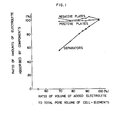
- Cell elements produced as described above were added severally in 100, 92.5, 90, 87.5, 85, 80, and 70 cc/cell of the electrolyte and then stood for 24 hours. After the standing, they were lifted from the containers and examined to determine the amounts of the electrolyte contained in the positive plates, negative plates, and separators. In the addition of 100 cc/cell a certain amount of free electrolyte apparently existed in the cell. In the addition of 100 cc/cell of the electrolyte, the volume of the electrolyte contained per unit weight was 0.14 cc/g for the positive active material, 0.17 cc/g for the negative active material, and 7.8 cc/g for the separators.
- the separators possess the voids which are necessary for the oxygen gas evolved at the positive plates during overcharging to the transported from the positive plates to the negative plates. It is, accordingly, expected that the efficiency of the absorption of the oxygen gas reaches an exceedingly high level when the amount of the electrolyte is decreased to a certain level.
- Sealed lead-acid batteries were obtained by inserting the cell elements assembled as described above in a container, welding a strap, joining a lid to the container, adding dilute sulfuric acid with 130 specific gravity at an amount of 100 cc/cell, and fitting in a safty valve with a venting pressure of 0.2 kg/cm 2 .
- the sealed lead-acid batteries thus obtained exihibited a 10-hour rate discharge capacity of 11 AH, a 10C (110 A) discharged duration of 3 minute 00 second, and a 5-second voltage at discharge of 1.80 V per unit cell.
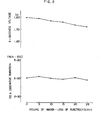
- These batteries were overcharged at a current of 3C (33A) to decrease forcedly 5, 10, 15, 20, and 25 cc in the volume of electrolyte per cell respectively.
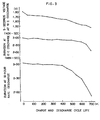
- a sealed lead-acid batteries which had the same construction as described above but contained the electrolyte of 95 cc/cell were subjected to alternating charging and discharging cycle-test of 4A discharge for 2 hours and 1.7 A recharge for 6 hours. At intervals of 50 cycles, the batteries were given a high-rate discharge test at a discharge current of 110A and a 3-hour rate discharge test. The change in the high-rate discharge characteristic along the advance of cycles is shown in Fig. 3. In the test, the efficiency of gas recombination averaged 80% during the first 50 ⁇ and it was substantially 100% in the subsequent cycles, indicating no decrease in the amount of the electrolyte. This means that the sealed lead-acid battery of this invention exhibits little or no sparing decline of the high-rate discharge characteristic after repeated operation of charging and discharging cycle and possesses a long service life.
- the discharge current density based on one side-surface area of the positive plate is about 0.3 A/cm 2 and the discharge duration is about one minute 50 seconds to about two minutes 30 secons.
- the discharge duration is about three minutes in spite of the condition that the discharge current density based on one side surface area of the positive plate is about 0.6 A/cm 2 , which is twice larger that of the conventional sealed lead-acid battery.
- the optimum thickness of the grids for positive plates is from 3 to 4 mm. By fixing the proper thickness of the grids within that range, the proper thickness of the separators is able to be used calculated eventually.
- this invention permits the sealed lead-acid battery to maintain the high-rate discharge characteristics during its long service life.
- the sealed lead-acid battery of this invention can be expected to have a longer service life than the sealed lead-acid battery conforming to the invention of U.S.P. 3,862,861 because grids of this invention are about three times as thick as that of the battery of U.S.P. 3,862,861.
- a sealed lead-acid battery of this invention can be obtained by selecting appropriately the positive plates, negative plates and the separators with a certain suitable range of pore diameter, specific surface area and other properties so as to become to the construction within the size of plate which comprises a larger amount of electrolyte contained in the positive and negative active materials than that in the separators and so as to be no decrease in the amount of electrolyte in the positive and negative active materials in spite of the condition that the total volume of electrolyte in the cell is reduced due to overcharging.
- the positive plates contain about 25 cc/cell
- negative plates contain about 23 cc/cell
- the separators contain about 34 cc/cell, representing the content ratios of about 30.5% for the positive plates, about 28.0% for the negative plates, and about 41.5% for the separators and indicating that the sum of the electrolyte contained in the positive plates and the negative plates is about 60% of the whole electrolyte so contained.
- the electrolyte contained in the positive and negative plates remains intact and that contained in the separators alone is lost when the whole amount of the electrolyte is decreased due to the water electrolysis during overcharging, therefor the ratio sum of the electrolyte contained in the positive plates and the negative plates to the whole amount of the electrolyte in the cell gradually increased from the aforementioned value of 60%.
- the high-rate discharge characteristic cannot be impaired.
- the separators for use in the battery must be selected so that the electrolyte absorption and retention power of capability of separators will be lower than there of the positive active material and the negative active material.
- the separators marketed under trademark designation Dexter #225B are of the separators usable for batteries of this kind.
- the separators of Dexter #225B have a specific surface area of about 2.5 m 2 /g, which is greater than that of the separators involved in the preferred embodiment by this invention, 1.45 m 2 /g and which is corresponding to be Sv of 6.25 m 2 /cc on the basis of its true specific gravity of 25 g/cc, which is a value larger than that of the negative active material.
- separators of Dexter #225B are used in the sealed lead-acid battery by this invention, there is a possibility that the pores in the positive plates and the negative plates will not be substantially filled with the electrolyte when the total amount of the electrolyte is decreased. Further, because separators of Dexter #225B have an average pore diameter of about 3 ⁇ m, which is a value smaller than the value about 7 p m shown by the separators of the preferred embodiment, and eventually the electrolyte absorption and retention power of separators is stronger there remains the above mentioned anxiety.
- the plates particularly the negative plates are required to have a larger specific surface area.
- the plates are required to be made of lead oxide powder with much smaller particle diameter above or to be made of a material incorporating therein various additives which is capable of notably increasing the specific surface area of the plates.
- the electrolyte should substantially fill the pores of the plates and there exist the unfilled voids in part of the pores of the separators is fulfilled by using separators which have a smaller, preferably slightly smaller electrolyte absorption and retention power or capability than the plates.
- separators which have a smaller, preferably slightly smaller electrolyte absorption and retention power or capability than the plates.
- Such a kind of separators is also usable in the sealed lead-acid battery which is required no or inferior high-rate discharge characteristics, namely such as the sealed lead-acid batteries for emergency power sources in which the distance between each plates is from about 1 to 2.5 mm.
- This kind of the sealed lead-acid battery is also embraced by the present invention. What is important is that the separators to be adopted should possess a smaller electrolyte absorption and retention power or capability than the plates.
- the inventors have not yet found the characteristic properties completely which permits suitable expression of the electrolyte absorption and retention power and capability.
- the electrolyte is distributed so that the pores in the active materials of the plates remain fully filled with the electrolyte and the pores in the separators permit partial existence of voids when the total volume of the electrolyte is decreased.
- the initial-stage high-rate discharge characteristic itself is controlled preponderantly by the distances between the positive plates and the negative plates, and the amount of electrolyte in positive active material and the negative active material, particularly the amount of sulfuric acid contained in the positive active material.
- the distances between each plate have a thickness of 2.0 mm and the sum of the amount of the electrolyte contained in the positive active material and the negative active material is 40% of the total electrolyte (then the content in the separators is 60%), high-rate discharge characteristic is not very satisfactory.
- the high-rate discharge characteristic of the battery may be further degraded because the amount of the electrolyte in the plates gradually decreases as the total electrolyte of the battery decreases owing to the water electrolysis.
- the produced battery is characterized by the matter that the initial-stage high-rate discharge characteristic can be retained intact in spite of the decrease of the total amount of the electrolyte due to water electrolysis.
- the sealed lead-acid battery by this invention when intended for an application necessitating the superior high-rate discharge characteristic, is disclosed by using separators with a thinner thickness than the plates, particularly the positive plates.
- the thickness of the separators is desired to be in the range of 0.4 to 0.25 times the thickness of the positive plates.
- the separators used therein had a thickness of about one third of the thickness of positive plates. The reason for such a range is that the high-rate discharge characteristic is degraded if the thickness exceeds 0.4 times and the possibility of short-circuiting arises if the thickness is less than 0.25 times.
- the total amount of the positive active material and the negative active material is greater than that of the electrolyte. That is, the capacity of the sealed lead-acid battery is affected by the amount of the electrolyte(namely the amount of sulfuric acid) and, even toward the end of discharge, the active materials still retain some undischarged portion.
- the electrolyte becomes nearly water.
- this phenomenon is outstanding conspicuous because the sum of the amount of the electrolyte contained in the positive plates and the negative plates is about 60% or more for the total electrolyte.
- the amount of impurity matters must be greater than the normally accepted levels or ranges because the sum of the amount of the electrolyte contained in the positive active material and the negative active material is greater than the amount of the electrolyte contained in the separators and because the thickness of the separators is thinner than that of the plates.
- the amount of the positive active material is desired to be larger than that of the negative active material. It is well known that in the conventional lead-acid battery with the free electrolyte the high-rate discharge characteristic at low temperature is controlled mainly by the negative plates. In the case of the sealed lead-acid battery by this invention, the high-rate discharge characteristic at low temperature is controlled not by the negative plates but by the amount of sulfuric acid present in the positive active material. It is, therefore, desirable for the pore volume contained in the positive active material to be equal to or greater than that in the negative active material.
- Vsp specific pore volume
- V SN negative active material
- the amount of the active material for the positive plates is desired to be 1.21 times or more than the amount for the negative plates, although the amount of the pores in positive plate is variable with the amount of sulfuric acid used in mixing the finely divided lead oxide powder.
- the positive plates are desired to be larger in the capacity than the negative plates in the sealed lead-acid battery by the present invention.
Landscapes
- Engineering & Computer Science (AREA)
- Manufacturing & Machinery (AREA)
- Chemical & Material Sciences (AREA)
- Chemical Kinetics & Catalysis (AREA)
- Electrochemistry (AREA)
- General Chemical & Material Sciences (AREA)
- Secondary Cells (AREA)
- Battery Electrode And Active Subsutance (AREA)
Applications Claiming Priority (2)
| Application Number | Priority Date | Filing Date | Title |
|---|---|---|---|
| JP198830/83 | 1983-10-24 | ||
| JP58198830A JPS6091572A (ja) | 1983-10-24 | 1983-10-24 | 密閉形鉛蓄電池 |
Publications (1)
| Publication Number | Publication Date |
|---|---|
| EP0141568A1 true EP0141568A1 (en) | 1985-05-15 |
Family
ID=16397623
Family Applications (1)
| Application Number | Title | Priority Date | Filing Date |
|---|---|---|---|
| EP84307042A Withdrawn EP0141568A1 (en) | 1983-10-24 | 1984-10-15 | Sealed lead-acid battery |
Country Status (4)
| Country | Link |
|---|---|
| US (1) | US4725516A (zh) |
| EP (1) | EP0141568A1 (zh) |
| JP (1) | JPS6091572A (zh) |
| CA (1) | CA1230642A (zh) |
Cited By (3)
| Publication number | Priority date | Publication date | Assignee | Title |
|---|---|---|---|---|
| EP0251683A2 (en) | 1986-06-27 | 1988-01-07 | Gates Energy Products, Inc. | High rate sealed lead-acid battery with ultrathin plates |
| EP0289596A1 (en) * | 1986-11-12 | 1988-11-09 | Hollingsworth & Vose Co | BATTERY WITH GAS RECOMBINATION AND MATCHING PLATE SEPARATOR. |
| CN102246344A (zh) * | 2009-12-25 | 2011-11-16 | 松下电器产业株式会社 | 控制阀式铅蓄电池 |
Families Citing this family (32)
| Publication number | Priority date | Publication date | Assignee | Title |
|---|---|---|---|---|
| JPS62122076A (ja) * | 1985-11-21 | 1987-06-03 | Japan Storage Battery Co Ltd | 密閉鉛蓄電池 |
| US5601945A (en) * | 1986-03-24 | 1997-02-11 | Ensci Inc. | Battery element containing porous substrates |
| US5549990A (en) * | 1986-03-24 | 1996-08-27 | Ensci Inc | Battery element containing porous particles |
| US5047300A (en) * | 1989-06-14 | 1991-09-10 | Bolder Battery, Inc. | Ultra-thin plate electrochemical cell |
| US5895732A (en) * | 1992-04-24 | 1999-04-20 | Ensci, Inc. | Battery element containing macroporous additives |
| JP4556250B2 (ja) * | 1998-09-25 | 2010-10-06 | 株式会社Gsユアサ | 鉛蓄電池 |
| CA2386764A1 (en) * | 1999-10-06 | 2001-04-12 | Kvg Technologies, Inc. | Battery paste |
| US6531248B1 (en) | 1999-10-06 | 2003-03-11 | Squannacook Technologies Llc | Battery paste |
| US6852444B2 (en) * | 2001-09-20 | 2005-02-08 | Daramic, Inc. | Reinforced multilayer separator for lead-acid batteries |
| US6869726B2 (en) * | 2001-09-20 | 2005-03-22 | Daramic, Inc. | Reinforced multilayer separator for lead-acid batteries |
| CN100346504C (zh) * | 2002-02-07 | 2007-10-31 | Kvg技术股份有限公司 | 由吸收性网筛、电解质的过滤作用及吸收性网筛形成的具有凝胶电解质的铅蓄电池 |
| US6929858B2 (en) * | 2002-03-25 | 2005-08-16 | Squannacook Technologies Llc | Glass fibers |
| US7159805B2 (en) * | 2002-03-25 | 2007-01-09 | Evanite Fiber Corporation | Methods of modifying fibers |
| JP4675156B2 (ja) * | 2005-05-25 | 2011-04-20 | 古河電池株式会社 | 制御弁式鉛蓄電池 |
| CN101091282B (zh) * | 2005-09-27 | 2014-09-03 | 古河电池株式会社 | 铅蓄电池及其制造方法 |
| JP2008243487A (ja) * | 2007-03-26 | 2008-10-09 | Furukawa Battery Co Ltd:The | 鉛電池 |
| JP2009016256A (ja) * | 2007-07-06 | 2009-01-22 | Gs Yuasa Corporation:Kk | 鉛蓄電池 |
| JP4434246B2 (ja) * | 2007-07-24 | 2010-03-17 | トヨタ自動車株式会社 | 空気電池システム |
| RU2533829C2 (ru) * | 2010-05-10 | 2014-11-20 | Син-Кобе Электрик Машинери Ко., Лтд. | Свинцово-кислотная аккумуляторная батарея |
| JP5618253B2 (ja) * | 2010-09-30 | 2014-11-05 | 株式会社Gsユアサ | 鉛蓄電池 |
| JP2013065443A (ja) * | 2011-09-16 | 2013-04-11 | Shin Kobe Electric Mach Co Ltd | 鉛蓄電池 |
| US20140212765A1 (en) * | 2011-10-14 | 2014-07-31 | Gs Yuasa International Ltd. | Valve regulated lead-acid battery |
| JP5831553B2 (ja) * | 2011-10-18 | 2015-12-09 | 新神戸電機株式会社 | 鉛蓄電池 |
| JP5780106B2 (ja) * | 2011-10-19 | 2015-09-16 | 株式会社Gsユアサ | 鉛蓄電池及びその製造方法 |
| WO2013073420A1 (ja) * | 2011-11-16 | 2013-05-23 | 新神戸電機株式会社 | 鉛蓄電池 |
| IN2015DN01816A (zh) * | 2012-12-21 | 2015-05-29 | Panasonic Ip Man Co Ltd | |
| WO2015079668A1 (ja) | 2013-11-29 | 2015-06-04 | 株式会社Gsユアサ | 鉛蓄電池 |
| EP3252863A4 (en) * | 2015-01-28 | 2018-11-14 | Hitachi Chemical Co., Ltd. | Lead storage cell and automobile provided with same |
| JP6836315B2 (ja) * | 2015-03-19 | 2021-02-24 | 株式会社Gsユアサ | 制御弁式鉛蓄電池 |
| JP6544126B2 (ja) * | 2015-08-05 | 2019-07-17 | 日立化成株式会社 | 制御弁式鉛蓄電池 |
| JP6830615B2 (ja) * | 2019-07-10 | 2021-02-17 | 株式会社Gsユアサ | 制御弁式鉛蓄電池 |
| CN111180816B (zh) * | 2019-12-31 | 2022-04-29 | 天能电池(芜湖)有限公司 | 确定铅酸蓄电池化成过程中电解水失重和挥发失重的方法 |
Citations (5)
| Publication number | Priority date | Publication date | Assignee | Title |
|---|---|---|---|---|
| DE2149660A1 (de) * | 1971-10-05 | 1973-04-12 | Bosch Gmbh Robert | Wartungsfreier bleiakkumulator |
| US3862861A (en) * | 1970-08-03 | 1975-01-28 | Gates Rubber Co | Maintenance-free type lead acid |
| FR2290048A1 (fr) * | 1974-10-31 | 1976-05-28 | Chloride Group Ltd | Elements et batteries d'accumulateur au plomb |
| GB2084790A (en) * | 1980-10-03 | 1982-04-15 | Gould Inc | Lead-acid batteries |
| EP0055888A2 (en) * | 1980-12-29 | 1982-07-14 | Gates Energy Products Inc. | Multicell recombining lead-acid battery |
Family Cites Families (6)
| Publication number | Priority date | Publication date | Assignee | Title |
|---|---|---|---|---|
| US3170819A (en) * | 1961-09-05 | 1965-02-23 | Electric Storage Battery Co | Electric battery |
| DE2509779B2 (de) * | 1975-03-06 | 1977-08-18 | Varta Batterie Ag, 3000 Hannover | Wartungsfreier bleiakkumulator |
| JPS5445755A (en) * | 1977-09-19 | 1979-04-11 | Yuasa Battery Co Ltd | Separator for storage battery |
| US4233379A (en) * | 1979-05-17 | 1980-11-11 | Johns-Manville Corporation | Separator for starved electrolyte lead/acid battery |
| JPS5787080A (en) * | 1980-11-19 | 1982-05-31 | Yuasa Battery Co Ltd | Sealed type lead-acid battery |
| ZA832713B (en) * | 1982-04-20 | 1984-08-29 | Evans Adlard & Co | Glass fibre paper separator for electrochemical cells |
-
1983
- 1983-10-24 JP JP58198830A patent/JPS6091572A/ja active Granted
-
1984
- 1984-10-15 EP EP84307042A patent/EP0141568A1/en not_active Withdrawn
- 1984-10-19 CA CA000465941A patent/CA1230642A/en not_active Expired
-
1985
- 1985-10-15 US US06/787,028 patent/US4725516A/en not_active Expired - Lifetime
Patent Citations (6)
| Publication number | Priority date | Publication date | Assignee | Title |
|---|---|---|---|---|
| US3862861A (en) * | 1970-08-03 | 1975-01-28 | Gates Rubber Co | Maintenance-free type lead acid |
| US3862861B1 (zh) * | 1970-08-03 | 1987-04-07 | ||
| DE2149660A1 (de) * | 1971-10-05 | 1973-04-12 | Bosch Gmbh Robert | Wartungsfreier bleiakkumulator |
| FR2290048A1 (fr) * | 1974-10-31 | 1976-05-28 | Chloride Group Ltd | Elements et batteries d'accumulateur au plomb |
| GB2084790A (en) * | 1980-10-03 | 1982-04-15 | Gould Inc | Lead-acid batteries |
| EP0055888A2 (en) * | 1980-12-29 | 1982-07-14 | Gates Energy Products Inc. | Multicell recombining lead-acid battery |
Non-Patent Citations (1)
| Title |
|---|
| PATENTS ABSTRACTS OF JAPAN, vol. 6, no. 170(E-128)[1048], 3rd September 1982; & JP - A - 57 87080 (YUASA DENCHI K.K.) 31-05-1982 * |
Cited By (5)
| Publication number | Priority date | Publication date | Assignee | Title |
|---|---|---|---|---|
| EP0251683A2 (en) | 1986-06-27 | 1988-01-07 | Gates Energy Products, Inc. | High rate sealed lead-acid battery with ultrathin plates |
| AU587901B2 (en) * | 1986-06-27 | 1989-08-31 | Hawker Energy Products Inc. | High rated sealed lead-acid battery with ultrathin plates |
| EP0289596A1 (en) * | 1986-11-12 | 1988-11-09 | Hollingsworth & Vose Co | BATTERY WITH GAS RECOMBINATION AND MATCHING PLATE SEPARATOR. |
| EP0289596A4 (en) * | 1986-11-12 | 1989-08-16 | Hollingsworth & Vose Co | BATTERY WITH GAS RECOMBINATION AND MATCHING PLATE SEPARATOR. |
| CN102246344A (zh) * | 2009-12-25 | 2011-11-16 | 松下电器产业株式会社 | 控制阀式铅蓄电池 |
Also Published As
| Publication number | Publication date |
|---|---|
| JPH0584033B2 (zh) | 1993-11-30 |
| CA1230642A (en) | 1987-12-22 |
| US4725516A (en) | 1988-02-16 |
| JPS6091572A (ja) | 1985-05-22 |
Similar Documents
| Publication | Publication Date | Title |
|---|---|---|
| US4725516A (en) | Sealed lead-acid battery | |
| US4401730A (en) | Sealed deep cycle lead acid battery | |
| EP0443451A1 (en) | Sealed lead-acid battery | |
| US20110027653A1 (en) | Negative plate for lead acid battery | |
| US4871428A (en) | Method for in situ forming lead-acid batteries having absorbent separators | |
| US20050084762A1 (en) | Hybrid gelled-electrolyte valve-regulated lead-acid battery | |
| US4444854A (en) | Electrochemical cell having internal short inhibitor | |
| JP4635325B2 (ja) | 制御弁式鉛蓄電池 | |
| JP2004014283A (ja) | 制御弁式鉛蓄電池 | |
| JP2006318659A (ja) | 鉛蓄電池 | |
| JP7331856B2 (ja) | 鉛蓄電池 | |
| KR870000967B1 (ko) | 무 보수 밀폐형 납산-전지 | |
| JPS61165956A (ja) | 密閉式鉛蓄電池 | |
| JP2006155901A (ja) | 制御弁式鉛蓄電池 | |
| JP3221154B2 (ja) | 密閉形鉛蓄電池 | |
| JP2982376B2 (ja) | 密閉形鉛蓄電池の製造方法 | |
| JP3101622B2 (ja) | ニッケル・水素アルカリ蓄電池 | |
| JP3035177B2 (ja) | 鉛蓄電池 | |
| JP2808685B2 (ja) | 鉛蓄電池 | |
| JP2002260717A (ja) | 制御弁式鉛蓄電池 | |
| JP3577709B2 (ja) | 密閉型鉛蓄電池 | |
| JPS58158874A (ja) | 鉛蓄電池 | |
| CA1166687A (en) | Electrochemical cell having internal short inhibitor | |
| JPH1040906A (ja) | 密閉形鉛蓄電池用負極板 | |
| JPS62193060A (ja) | 密閉式鉛蓄電池 |
Legal Events
| Date | Code | Title | Description |
|---|---|---|---|
| PUAI | Public reference made under article 153(3) epc to a published international application that has entered the european phase |
Free format text: ORIGINAL CODE: 0009012 |
|
| AK | Designated contracting states |
Designated state(s): DE FR GB IT SE |
|
| 17P | Request for examination filed |
Effective date: 19851104 |
|
| 17Q | First examination report despatched |
Effective date: 19860613 |
|
| STAA | Information on the status of an ep patent application or granted ep patent |
Free format text: STATUS: THE APPLICATION IS DEEMED TO BE WITHDRAWN |
|
| 18D | Application deemed to be withdrawn |
Effective date: 19890901 |
|
| RIN1 | Information on inventor provided before grant (corrected) |
Inventor name: MATSUMARU, YUJI Inventor name: YAMASHITA, JOJI Inventor name: KISHIMOTO, KENJIRO Inventor name: OKADA, KAZUO |