EP0141000A2 - Umkehrfenster - Google Patents
Umkehrfenster Download PDFInfo
- Publication number
- EP0141000A2 EP0141000A2 EP83307982A EP83307982A EP0141000A2 EP 0141000 A2 EP0141000 A2 EP 0141000A2 EP 83307982 A EP83307982 A EP 83307982A EP 83307982 A EP83307982 A EP 83307982A EP 0141000 A2 EP0141000 A2 EP 0141000A2
- Authority
- EP
- European Patent Office
- Prior art keywords
- sash
- vertical
- frames
- window
- movable link
- Prior art date
- Legal status (The legal status is an assumption and is not a legal conclusion. Google has not performed a legal analysis and makes no representation as to the accuracy of the status listed.)
- Withdrawn
Links
Images


Classifications
-
- E—FIXED CONSTRUCTIONS
- E05—LOCKS; KEYS; WINDOW OR DOOR FITTINGS; SAFES
- E05D—HINGES OR SUSPENSION DEVICES FOR DOORS, WINDOWS OR WINGS
- E05D15/00—Suspension arrangements for wings
- E05D15/40—Suspension arrangements for wings supported on arms movable in vertical planes
- E05D15/44—Suspension arrangements for wings supported on arms movable in vertical planes with pivoted arms and vertically-sliding guides
-
- E—FIXED CONSTRUCTIONS
- E05—LOCKS; KEYS; WINDOW OR DOOR FITTINGS; SAFES
- E05Y—INDEXING SCHEME RELATING TO HINGES OR OTHER SUSPENSION DEVICES FOR DOORS, WINDOWS OR WINGS AND DEVICES FOR MOVING WINGS INTO OPEN OR CLOSED POSITION, CHECKS FOR WINGS AND WING FITTINGS NOT OTHERWISE PROVIDED FOR, CONCERNED WITH THE FUNCTIONING OF THE WING
- E05Y2800/00—Details, accessories and auxiliary operations not otherwise provided for
- E05Y2800/74—Specific positions
- E05Y2800/742—Specific positions abnormal
- E05Y2800/744—Specific positions abnormal cleaning or service
-
- E—FIXED CONSTRUCTIONS
- E05—LOCKS; KEYS; WINDOW OR DOOR FITTINGS; SAFES
- E05Y—INDEXING SCHEME RELATING TO HINGES OR OTHER SUSPENSION DEVICES FOR DOORS, WINDOWS OR WINGS AND DEVICES FOR MOVING WINGS INTO OPEN OR CLOSED POSITION, CHECKS FOR WINGS AND WING FITTINGS NOT OTHERWISE PROVIDED FOR, CONCERNED WITH THE FUNCTIONING OF THE WING
- E05Y2900/00—Application of doors, windows, wings or fittings thereof
- E05Y2900/10—Application of doors, windows, wings or fittings thereof for buildings or parts thereof
- E05Y2900/13—Application of doors, windows, wings or fittings thereof for buildings or parts thereof characterised by the type of wing
- E05Y2900/148—Windows
Definitions
- This invention relates to a reversible window structure capable of reversing a sash member housed in a window frame. More particularly, the invention is concerned with a reversible window structure which can completely prevent protrusion of the sash member from the window frame toward an inward side during the reversing of the sash member.
- the sash member can be reversed by a very light operating force by moving its centre of gravity at a substantially horizontal state toward an outward direction.
- the inventors have previously developed a reversible window structure utilizing the horizontal rotation system in which the sash member can be reversed without protruding toward the indoor side by freely moving one side end in up and down direction of the sash member along the vertical window frames in up and down direction and pivotally supporting the vertical sash member at a position substantially corresponding to a gravity centre of the sash member. Further, the inventors have made various studies with respect to the concrete improvement of such a reversible window structure.
- the upper end of the vertical sash member is pivotally supported by a lower end of a supported arm pivoted to an upper portion of the vertical window frame at such a position that the vertical sash member is substantially at the same level as the gravity centre thereof.
- the gravity centre of the sash member changes in up and down direction in accordance with the pivot radius of the arm during the reversing of the sash member, so that a large operating force is required and at the same time the reverse operation is apt to become unstable.
- the invention aims to provide a reversible window structure utilizing a horizontal rotation system, in which the reversing operation of the sash member can be conducted in stable manner by means of a light operating force by supporting the vertical sash member so as to move the gravity centre of the sash member in an outwards direction at a substantially horizontal trajectory, and the reversing of the sash member can safely be performed without being protruded toward an indoor side even if a curtain, blind or the like is present inside the window, and which is sufficiently applicable to windows with a larger opening width.
- a roller 14 for drawing the sash member is pivoted to an upper surface side of the upper sash frame 5 through another roller fitting member 13 and further a lock handle 15 is secured to an indoor side of the lower sash frame 8.
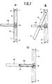
- a link assembly 20 As shown in Fig. 4. ( The link assembly to be attached to the left-side vertical window frame 2 is omitted in Fig.2.)
- the link assembly 20 comprises a fixed link member 22 secured to the vertical window frame 2 or 3 through a screw 21, first and second movable link members 23, 24 pivotably connected to the fixed link member 22, and a third movably link member 25 pivotably connected to the first and second movable link members 23, 24.
- a bent portion at upper end side of the fixed link member 22 is pivotably connected to the upper end side of the first movable link member 23 through a pivot pin 26, while a bent portion at lower end side of the fixed link member 22 is pivotably connected to the upper end side of the second movable link member 24 through a pivot pin 27.
- the lower end side of the first movable link member 23 is pivotably connected to the middle portion of the third movable link member 25 through a pivot pin 28, while the lower end side of the second movable link member 24 is pivotably connected to the lower end side of the third movable link member 25 through a pivot pin 29.
- To the upper end side of the third movable link member 25 is pivotably connected to a bracket 32 for attaching the sash member through a pivot pin 31.
- the bracket 32 is fixed to each of the vertical sash frames 6, 7 through screws 33 as.show in Fig. 2 ( omitted at the side of the frame 6 ).
- the lengths of the fixed link member 22 and the first, second and third movable link members 23, 24, 25 as well as the positions of the pivot pins 26, 27, 28 and 29 are so determined that the position of the pivot pin 31 at the third movable link member 25 moves on an approximately linear trajectory in a substantially horizontal direction or a direction substantially perpendicular to the fixed link member 22 when moving the first, second and third movable link members 23, 24 and 25.
- the dimensions of the link assembly may be selected as follows :
- the roller 12 disposed on the upper end of the sash member 10 is inserted into the concave groove 18 of each of the left-side and right-side vertical window frames 2, 3, while the bracket 32 is pivotably connected to each of the vertical sash frames 6, 7 at a position substantially corresponding to the gravity center of the sash member 10 through the pivot pin 31.
- the roller 12 moves downwards inside the concave groove 18 while holding the gravity center of the sash member 10 at substantially the same level through the pivot pin 31 existent in the upper end portion of the third movable link member 25 of the link assembly 20.
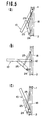
- the lower end of the sash member 10 is further pushed toward the outdoor direction so as to move the upper end of the sash member 10 downwards, during which the gravity center of the sash member 10 is also held at substantially'the same level by the link assembly 20-and at the same time it moves on a trajectory of line L shown in Feg. 6 at a substantially horizontal state in the outdoor direction.
- the gravity center of the sash member 10 moves on the trajectory of the line L in the indoor direction, so that there is caused no change of the gravity center in up and down direction. Therefore, the reversing operation of the sash member 10 can be conducted very stably through a considerably light operating force.
- the sash member 10 is pushed downward at the side of the roller 12 to change into the reversed state.
- the link assembly 20 is used as a means for pivotably supporting the vertical sash frames 6, 7 at a position substantially corresponding to the gravity center of the sash member and guiding the thus supported portion at a substantially horizontal state in the outdoor direction.
- the invention is not intended to limit the use of such a link assembly and may adopt mechanisms as shown in Fig. 7 to 10 without departing from the scope of the invention.
- the vertical sash frame (6,7) can pivotably be supported at substantially the same level as the gravity center of the sash member and the thus supported portion can be guided in the outdoor direction'at the substantially horizontal state.
- the gravity center of the sash member 10 is always supported at the position of the gravity center without moving in up and down direction, so that the reversing operation of the sash member 10 can stably be performed through a considerably small operating force.
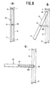
- a horizontal expansion rod 45 a top of which moving in the outdoor direction at a horizontal state, is fixed to each of the vertical window frames 2, 3 at a position substantially corresponding to the gravity center of the sash member at the closed state thereof, while the top of the horizontal expansion rod 45 is pivotably connected to each of the vertical sash frames 6, 7 through the pivot pin 41.
- the vertical sash frame ( 6, 7) can also pivotably be supported at substantially the same level as the gravity center of the sash member and the thus supported portion can be guided in the outdoor direction at the horizontal state.
- the reversing operation of the sash member 10 can be performed through a considerably light operating force without moving in up and down direction.
- a unidirectionally bendable chain 51 is used instead of the link assembly 20.
- a support member 52 for the chain 51 is secured to each of the vertical window frames 2, 3 at a position substantially corresponding to the gravity center of the sash member at the closed state thereof, while one end of the chain 51 is pivoted to the support pin 41 arranged on each of the vertical sash frames 6, 7 and the other end of the chain 51 is slidably held inside each of the vertical window frames 2, 3.
- the vertical sash frame (6, 7) can also pivotably be supproted at substantially the same level as the gravity center of the sash member and the thus supported portion can be guided in the outdoor direction at the substantially horizontal state.
- the reversing operation of the sash member 10 can be performed through a considerably light operating force without moving the gravity center of the sash member in up and down direction.
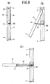
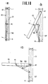
- Fig. 10 is shown another embodiment of the link mechanism, wherein an upper end.of a first movable link member 55 is pivotably connected to each of the vertical window frames 2, 3 at a position substantially corresponding to the gravity center of the sash member at the closed state thereof, while a lower end of the first movable link member 55 is pivotably connected to a middle portion of a second movable link member 56. Further, an upper end of the second movable link member 56 is pivoted to the support pin 41 arranged on each of the vertical sash frames 6, 7 while a lower end of the second movable link member 56 is freely moved along.a guide groove 57 disposed on each of the vertical window frames 2, 3 in up and down direction.
- the vertical sash member ( 6, 7 ) can also pivotably supported at substantially the same level as the gravity center of the sash member and the thus supported portion can be guided in the outdoor direction at the substantially horizontal state.
- the reversing operation of the sash member 10 can be performed through a considerably light operating force without substantially moving the gravity center of the sash member in up and down direction.
- one end side in up and down direction of the sash member is freely moved along the vertical window frames in up and down direction, while the vertical sash members are pivotably supported at substantially the same level as the gravity center of the sash member and the thus supported portion can be guided in the outdoor direction at the substantially horizontal state. Therefore, the gravity center of the sash member is moved in the substantially horizontal direction during the reversing of the sash member and there is caused no large fluctuation of the gravity center in up and down direction as in the conventional window structures, so that the reversing operation of the sash member can stably be conducted through a considerably light operating force.
- the sash member is always supported by that portion of the vertical sash frame which locates at the same level as the gravity center of the sash member, so that there is produced no cantilever state of the sash member as in the conventional window structure.
- the invention is applied to windows having a larger opening width, there is caused no deformation of the sash frame assembly and consequently the airtightness and sound insulting property of the window structure can satisfactorily be retained over a long period of time.
- the sash member never protrudes from the window frame assembly toward the indoor side in the reversing, so that the reversing operation can be conducted very safely without injuring any person existent in the indoor side.
Applications Claiming Priority (2)
| Application Number | Priority Date | Filing Date | Title |
|---|---|---|---|
| JP58186684A JPS6080673A (ja) | 1983-10-07 | 1983-10-07 | 反転窓 |
| JP186684/83 | 1983-10-07 |
Publications (2)
| Publication Number | Publication Date |
|---|---|
| EP0141000A2 true EP0141000A2 (de) | 1985-05-15 |
| EP0141000A3 EP0141000A3 (de) | 1986-03-26 |
Family
ID=16192827
Family Applications (1)
| Application Number | Title | Priority Date | Filing Date |
|---|---|---|---|
| EP83307982A Withdrawn EP0141000A3 (de) | 1983-10-07 | 1983-12-23 | Umkehrfenster |
Country Status (3)
| Country | Link |
|---|---|
| US (1) | US4616443A (de) |
| EP (1) | EP0141000A3 (de) |
| JP (1) | JPS6080673A (de) |
Cited By (7)
| Publication number | Priority date | Publication date | Assignee | Title |
|---|---|---|---|---|
| EP0351340A1 (de) * | 1988-07-12 | 1990-01-17 | FERCO INTERNATIONAL Usine de Ferrures de Bâtiment Société à responsabilité limitée dite | Beschlag für Kippfenster |
| GB2225050A (en) * | 1988-11-17 | 1990-05-23 | Ja Jo Ind As | Horizontally hinged swivelling window |
| EP0542050A1 (de) * | 1991-11-11 | 1993-05-19 | Ernst Lahmann | Beschlag für um 180 Grad nach innen oder aussen kipp- bzw. klappbare Flügel von Fenstern oder dergleichen |
| GB2267535A (en) * | 1992-06-02 | 1993-12-08 | W M S Group Ltd | Mounting assembly for a reversible window |
| WO2000028184A1 (en) * | 1998-11-09 | 2000-05-18 | Steinar Flo | Fitting for a reversing window |
| WO2008040345A1 (en) * | 2006-10-05 | 2008-04-10 | Vkr Holding A/S | Fitting for a reversible structure and a reversible window structure comprising a fitting |
| EP2372063A2 (de) | 2010-03-29 | 2011-10-05 | VKR Holding A/S | Umkehrbare Fensteranordnung |
Families Citing this family (16)
| Publication number | Priority date | Publication date | Assignee | Title |
|---|---|---|---|---|
| SE9202552L (sv) * | 1992-09-07 | 1994-03-08 | Teknoskand Invent Ab | Ett fönster, en dörr eller liknande och i synnerhet ett härför avsett glidbeslag |
| NZ245359A (en) * | 1992-12-03 | 1997-08-22 | Interlock Ind Ltd | A window stay with a diagonally stepped short arm, and a long arm, has a pivot coupling between other pivot couplings when the stay is closed |
| WO1995024538A1 (en) * | 1994-03-11 | 1995-09-14 | Andersen Corporation | Window operator |
| USD408274S (en) * | 1997-04-03 | 1999-04-20 | Truth Hardware Corporation | Outer surface of an operator housing |
| PL367977A1 (en) * | 2001-08-22 | 2005-03-21 | Vkr Holding A/S | A reversible window, use thereof and a guide device for a reversible window |
| US20040149307A1 (en) * | 2002-12-18 | 2004-08-05 | Klaus Hartig | Reversible self-cleaning window assemblies and methods of use thereof |
| ATE503072T1 (de) * | 2004-10-20 | 2011-04-15 | Walch Gmbh | Beschlag für ein wendefenster und wendefenster mit einem solchen beschlag |
| CH702221B1 (de) * | 2005-04-14 | 2011-05-31 | 4B Fassaden Ag | Beschlag für ein Wendefenster. |
| WO2006121471A2 (en) * | 2005-01-11 | 2006-11-16 | Pella Corporation | Window assembly with movable interior sash |
| SE530170C2 (sv) * | 2005-11-25 | 2008-03-18 | Assa Ab | Ledmekanism för vändbara fönster, dörrar och liknande |
| US20080016781A1 (en) * | 2006-07-21 | 2008-01-24 | Kuan-Chin Chung | Connecting assembly for pushing outward window frame |
| CN102828666B (zh) * | 2006-09-20 | 2015-04-08 | 奥依列斯Eco株式会社 | 自然通风窗 |
| JP5373574B2 (ja) * | 2009-12-02 | 2013-12-18 | 株式会社Lixil | 開口部装置 |
| US8482906B2 (en) * | 2009-12-10 | 2013-07-09 | Ccs-Inc. | Harsh environment liquid crystal display (LCD) enclosure |
| JP5421801B2 (ja) * | 2010-01-19 | 2014-02-19 | 株式会社Lixil | 開口部装置 |
| SE538810C2 (sv) * | 2014-03-28 | 2016-12-13 | Öhman Hans | Mekanism för svängbart fönster |
Citations (4)
| Publication number | Priority date | Publication date | Assignee | Title |
|---|---|---|---|---|
| DE203289C (de) * | ||||
| LU37848A1 (de) * | ||||
| FR1516204A (fr) * | 1967-01-26 | 1968-03-08 | Mawhin Jean Denis | Nouvelle fenêtre auto-équilibrée à ouverture à soufflet ou à l'italienne |
| FR2274768A1 (fr) * | 1974-06-12 | 1976-01-09 | Mawhin Jean Denis | Fenetre a ouvrant reversible auto-equilibre avec ouverture interieure en soufflet ou projetante a l'italienne |
Family Cites Families (9)
| Publication number | Priority date | Publication date | Assignee | Title |
|---|---|---|---|---|
| US1011940A (en) * | 1911-08-15 | 1911-12-19 | Anna K Gilson | Rain and wind shield for automobiles. |
| US1511683A (en) * | 1923-06-19 | 1924-10-14 | Arthur C Soule | Sash mounting |
| US2017543A (en) * | 1933-10-16 | 1935-10-15 | George L Curtis | Supporting and adjusting hardware for sashes and the like |
| US2718675A (en) * | 1951-07-16 | 1955-09-27 | John M Olsen | Reversible sash hardware |
| NO122890B (de) * | 1969-05-19 | 1971-08-30 | D Vaa | |
| BE782980Q (fr) * | 1971-08-09 | 1978-09-01 | Vaa Dyre | Fenetre pivotante |
| GB1471700A (en) * | 1973-06-22 | 1977-04-27 | Anvar | Window |
| NO134633C (de) * | 1975-04-30 | 1976-11-17 | Austnes Leif N | |
| GB1552917A (en) * | 1976-02-02 | 1979-09-19 | Bierlich J H | Window assemblies |
-
1983
- 1983-10-07 JP JP58186684A patent/JPS6080673A/ja active Pending
- 1983-12-23 EP EP83307982A patent/EP0141000A3/de not_active Withdrawn
- 1983-12-27 US US06/565,805 patent/US4616443A/en not_active Expired - Fee Related
Patent Citations (4)
| Publication number | Priority date | Publication date | Assignee | Title |
|---|---|---|---|---|
| DE203289C (de) * | ||||
| LU37848A1 (de) * | ||||
| FR1516204A (fr) * | 1967-01-26 | 1968-03-08 | Mawhin Jean Denis | Nouvelle fenêtre auto-équilibrée à ouverture à soufflet ou à l'italienne |
| FR2274768A1 (fr) * | 1974-06-12 | 1976-01-09 | Mawhin Jean Denis | Fenetre a ouvrant reversible auto-equilibre avec ouverture interieure en soufflet ou projetante a l'italienne |
Cited By (11)
| Publication number | Priority date | Publication date | Assignee | Title |
|---|---|---|---|---|
| EP0351340A1 (de) * | 1988-07-12 | 1990-01-17 | FERCO INTERNATIONAL Usine de Ferrures de Bâtiment Société à responsabilité limitée dite | Beschlag für Kippfenster |
| FR2634248A1 (fr) * | 1988-07-12 | 1990-01-19 | Ferco Int Usine Ferrures | Ferrures d'articulation pour chassis ouvrant a l'italienne |
| GB2225050A (en) * | 1988-11-17 | 1990-05-23 | Ja Jo Ind As | Horizontally hinged swivelling window |
| GB2225050B (en) * | 1988-11-17 | 1993-06-16 | Ja Jo Ind A S | An arrangement in fittings for a horizontally hinged swivelling window |
| EP0542050A1 (de) * | 1991-11-11 | 1993-05-19 | Ernst Lahmann | Beschlag für um 180 Grad nach innen oder aussen kipp- bzw. klappbare Flügel von Fenstern oder dergleichen |
| GB2267535A (en) * | 1992-06-02 | 1993-12-08 | W M S Group Ltd | Mounting assembly for a reversible window |
| GB2267535B (en) * | 1992-06-02 | 1995-11-01 | * The W M S Group Ltd | Mounting assembly for a window |
| WO2000028184A1 (en) * | 1998-11-09 | 2000-05-18 | Steinar Flo | Fitting for a reversing window |
| WO2008040345A1 (en) * | 2006-10-05 | 2008-04-10 | Vkr Holding A/S | Fitting for a reversible structure and a reversible window structure comprising a fitting |
| EP2372063A2 (de) | 2010-03-29 | 2011-10-05 | VKR Holding A/S | Umkehrbare Fensteranordnung |
| EP2372063A3 (de) * | 2010-03-29 | 2014-07-16 | VKR Holding A/S | Umkehrbare Fensteranordnung |
Also Published As
| Publication number | Publication date |
|---|---|
| US4616443A (en) | 1986-10-14 |
| JPS6080673A (ja) | 1985-05-08 |
| EP0141000A3 (de) | 1986-03-26 |
Similar Documents
| Publication | Publication Date | Title |
|---|---|---|
| EP0141000A2 (de) | Umkehrfenster | |
| US4364201A (en) | Full-opening window linkage assembly | |
| KR950010990B1 (ko) | 창 자물쇠 | |
| DE69910465D1 (de) | Betätigungsvorrichtung für Tür- oder Fensterkonstruktionen mit schwenkbaren Flügelelementen | |
| JP2914371B1 (ja) | スクリーンの係止構造 | |
| JP3100990B2 (ja) | 雨 戸 | |
| JPH048223Y2 (de) | ||
| JPH05558Y2 (de) | ||
| KR870000546Y1 (ko) | 중절창(中折窓) | |
| JP3973030B2 (ja) | シャッタ | |
| KR890004582Y1 (ko) | 돌출창에서 새시를 개방 위치에 보유시키는 장치 | |
| JPH0420129Y2 (de) | ||
| JPH031967Y2 (de) | ||
| KR0139200Y1 (ko) | 수직형 자동 블라인드의 안내봉 처짐 방지장치 | |
| JPH0613981Y2 (ja) | 天窓の開閉装置 | |
| JPH0332716Y2 (de) | ||
| JPH065493Y2 (ja) | 電動雨戸におけるギヤドワイヤの収納構造 | |
| JPH0458551B2 (de) | ||
| JP2514889B2 (ja) | サッシ窓のピボット変換装置 | |
| JPS6244054Y2 (de) | ||
| JPH08260845A (ja) | 出窓用雨戸 | |
| JP3303223B2 (ja) | 辷り出し窓の開閉装置 | |
| JPS5929114Y2 (ja) | 開き窓 | |
| JPH0420130Y2 (de) | ||
| JP2707033B2 (ja) | 出窓用雨戸 |
Legal Events
| Date | Code | Title | Description |
|---|---|---|---|
| PUAI | Public reference made under article 153(3) epc to a published international application that has entered the european phase |
Free format text: ORIGINAL CODE: 0009012 |
|
| AK | Designated contracting states |
Designated state(s): CH DE FR GB LI |
|
| 17P | Request for examination filed |
Effective date: 19850928 |
|
| PUAL | Search report despatched |
Free format text: ORIGINAL CODE: 0009013 |
|
| AK | Designated contracting states |
Kind code of ref document: A3 Designated state(s): CH DE FR GB LI |
|
| STAA | Information on the status of an ep patent application or granted ep patent |
Free format text: STATUS: THE APPLICATION IS DEEMED TO BE WITHDRAWN |
|
| 18D | Application deemed to be withdrawn |
Effective date: 19861004 |
|
| RIN1 | Information on inventor provided before grant (corrected) |
Inventor name: ARAKI, TOKIO Inventor name: AOKI, IWAO |