EP0139916A2 - Initialisation dans un système de communication à plusieurs stations avec transfert d'un signal "droit à émette" - Google Patents
Initialisation dans un système de communication à plusieurs stations avec transfert d'un signal "droit à émette" Download PDFInfo
- Publication number
- EP0139916A2 EP0139916A2 EP84109277A EP84109277A EP0139916A2 EP 0139916 A2 EP0139916 A2 EP 0139916A2 EP 84109277 A EP84109277 A EP 84109277A EP 84109277 A EP84109277 A EP 84109277A EP 0139916 A2 EP0139916 A2 EP 0139916A2
- Authority
- EP
- European Patent Office
- Prior art keywords
- station
- token
- stations
- state
- list
- Prior art date
- Legal status (The legal status is an assumption and is not a legal conclusion. Google has not performed a legal analysis and makes no representation as to the accuracy of the status listed.)
- Withdrawn
Links
- 238000004891 communication Methods 0.000 title claims abstract description 95
- 230000008859 change Effects 0.000 claims abstract description 14
- 230000000737 periodic effect Effects 0.000 claims abstract description 10
- 238000000034 method Methods 0.000 claims description 20
- 238000012546 transfer Methods 0.000 claims description 15
- 230000001360 synchronised effect Effects 0.000 abstract description 7
- 230000008602 contraction Effects 0.000 abstract 1
- 238000011423 initialization method Methods 0.000 abstract 1
- 230000005540 biological transmission Effects 0.000 description 13
- 230000004044 response Effects 0.000 description 9
- 230000007246 mechanism Effects 0.000 description 8
- 238000010586 diagram Methods 0.000 description 5
- 230000002950 deficient Effects 0.000 description 4
- XOJVVFBFDXDTEG-UHFFFAOYSA-N Norphytane Natural products CC(C)CCCC(C)CCCC(C)CCCC(C)C XOJVVFBFDXDTEG-UHFFFAOYSA-N 0.000 description 3
- 230000000694 effects Effects 0.000 description 3
- 230000007704 transition Effects 0.000 description 3
- 230000001934 delay Effects 0.000 description 2
- 238000001514 detection method Methods 0.000 description 2
- 238000009472 formulation Methods 0.000 description 2
- 230000006870 function Effects 0.000 description 2
- 230000000977 initiatory effect Effects 0.000 description 2
- 239000000203 mixture Substances 0.000 description 2
- 230000008520 organization Effects 0.000 description 2
- 230000008447 perception Effects 0.000 description 2
- 238000010420 art technique Methods 0.000 description 1
- 230000001364 causal effect Effects 0.000 description 1
- 238000006243 chemical reaction Methods 0.000 description 1
- 238000010276 construction Methods 0.000 description 1
- 238000012937 correction Methods 0.000 description 1
- 230000001419 dependent effect Effects 0.000 description 1
- 230000007717 exclusion Effects 0.000 description 1
- 230000006872 improvement Effects 0.000 description 1
- 230000003993 interaction Effects 0.000 description 1
- 238000012423 maintenance Methods 0.000 description 1
- 230000007257 malfunction Effects 0.000 description 1
- 238000012544 monitoring process Methods 0.000 description 1
- 238000012545 processing Methods 0.000 description 1
- 239000007858 starting material Substances 0.000 description 1
- 230000009897 systematic effect Effects 0.000 description 1
Images


Classifications
-
- H—ELECTRICITY
- H04—ELECTRIC COMMUNICATION TECHNIQUE
- H04L—TRANSMISSION OF DIGITAL INFORMATION, e.g. TELEGRAPHIC COMMUNICATION
- H04L12/00—Data switching networks
- H04L12/28—Data switching networks characterised by path configuration, e.g. LAN [Local Area Networks] or WAN [Wide Area Networks]
- H04L12/40—Bus networks
- H04L12/407—Bus networks with decentralised control
- H04L12/417—Bus networks with decentralised control with deterministic access, e.g. token passing
Definitions
- the present invention relates to communication systems and in particular to non-contention communication systems utilizing a single conceptualized token which is passed between stations communicating on a single bus, wherein each station when "owning" the token has the right, to the exclusion of other stations, to initiate high level message transmissions and, if desired, to cause other stations to transmit high level reply messages.
- Multi-station communication systems typically reside in one of two major categories, master controlled systems and master-less systems.
- the former category utilizes a central processing unit or other supervisory control which observes and dictates which station has access to the commonly shared data transmission resource; typically the bus interconnecting the various stations.
- the present invention is a master-less communication system.
- contention systems With respect to master-less communication systems, two general categories exist; namely, contention systems and token pass systems.
- the former contention systems are unlike the present invention in that they allow multiple stations to contend for access to the bus as the general - means for transferring control of the bus from one station to another station.
- the present invention although allowing for the possibility of contention when multiple stations simultaneously demand access to the token, generally only uses a contention-less token pass system.
- Ethernet TM Ethernet TM
- Metcalfe et al allows any station connected to the bus to transmit information provided that the bus is clear just prior to and during the transmission. If it detects noise on the bus while transmitting, it is assumed that an interference or collision has occurred between itself and at least one other station attempting to transmit information on the bus at the same time. In order to correct this problem the transmitter section is disabled on each station and a random number generator is used to select an interval of time at the completion of which the next attempt at transmission will take place.
- a counter counts the number of interferences, or collisions, which occur in the attempted transmissions of one data packet and weights the mean of the random number generator accordingly. In this way, the stations attempting to transmit will reattempt to transmit at different times and thus, in time, eliminate the contention between the stations.
- the present invention does not utilize such a contention or collision detection system but rather uses the concept of a token which is passed from one station to another such that each station when owning the token has, during that time, the exclusive right to initiate high level message transmissions as well as to request return high level messages from any other station.
- a failure of a station to detect the transfer of the token from itself to the next addressed station within a predetermined time causes the station which originally had the token to retransmit a new SEL signal with a new address so as to transfer the token to a different station.
- This reference does not disclose the concept of an arc of control wherein the present token owner (holder) knows both the station from which it received the token as well as the station to which it is to next transfer the token.
- This arc of control in combination with a demand window by which the present token owner can transfer the token to a demander not in the token list prov-ides the capability of both patching in and patching out stations to the token list of stations presently passing ownership of the token on a systematic basis.
- Imaizumi et al also neither discloses nor suggests the concept of automatically changing the handshaking protocol between token passing stations.
- Imaizumi et al further does not disclose or suggest the binding concept of the present invention wherein stations may have physical connection to the bus and yet never have the possibility of obtaining the token for control of the bus. These stations are thus only able to respond to other stations which can be token owners.
- the binding concept allows the communications system to interconnect with relatively low level access stations which would otherwise be incapable of transmitting information on the bus.
- the present invention through use of its underlying perceived events and their causal effect through rule interaction to change station states, can be reconfigured to form new and different communication systems having different access mechanism protocols depending upon the particular requirements of a communication network desired by the user.
- a synchronized serial bus communications system utilizing token passing is described.
- the commonly shared wire or bus is a passive communication vehicle onto which a plurality of stations interconnect for communication therebetween.
- each station contains a plurality of access mechanism modules, the modules representing changes of state based on rules representing actions to be taken when events are perceived by a station.
- Each station when possessing, holding, or owning the token (these verbs are used synonymously with respect to the token) is the only station that can initiate the transfer of non- access type messages (called high level messages in this document) over the bus to other stations and which can also command the transmission of high level messages from other stations to itself (surrogate message transfers to third party stations are not utilized in the present invention, though could be if desired).
- Once token ownership is obtained by a station the manner of data communication between that station and another station can meet with one or more well known standards such as the International Standards Organization's high level data link controller (HDLC) described in their document number ISO/DIS 3389.2.
- HDLC High level data link controller
- Some of the fundamental attributes of the present invention's access mechanism are its technique for determining which station is to next own the token by each station knowing its FROM and TO station, how to patch in and patch out, and automatic token pass handshake protocol transitions depending upon the pristine nature of previous token passes between the particular stations. Furthermore, the present invention describes the capability of special slave stations interconnecting to the bus which have no mechanism for their own access of the token, yet which can communicate through master stations which do have token access capabilities.
- the access mechanism of the present invention provides the ability of any station (other than slave stations mentioned above) to potentially be on a token list (loop or ring) of stations which periodically obtain ownership of the token.
- each station passes the token according to an overall protocol comprising a set of interconnected states whose transitions depend upon particular events occurring as perceived by the stations and acted upon by governing rules.
- Typical of these rules are that only one token can exist at a single time with respect to any group of stations connected to a single bus; that each station knows the same overall state protocol as all other stations which have potential access 'to the token; that the load or degree of use of data communications can be observed by any station by listening to the communications transmitted across the bus, including the amount of time for stations to acquire the token.
- a station can ascertain the number of other stations connected to the bus having token access; that is, how many are part of the token list.
- the rules can be thought of as the particular format for receiving messages which initiate changes of state and thus, that a particular change from one stable state to another cannot occur unless certain events, such as timeouts or messages, occur.
- the rules defining the way that messages must occur can be considered the rules for changing state.
- the states themselves are thus the configurations that any station can be found in, while the rules define the way stations change states as based upon perceived events.
- the interconnections of the states to each other depending upon the events observed by that station define the overall state map which represents a particular communication system.
- Certain underlying configurations of the state map form integral subsets of the communication system.
- One such underlying subset of states comprises the arc of control in which each station in the token list knows both the station from which it receives the token (the FROM station) as well as the station to whom the station passes the token (the TO station).
- the FROM station, the present token owner station and the TO station form a conceptual arc if the token list is considered a circle with each station resident at a different location on the circumference of the circle. This arc moves around the conceptualized circle as the token is passed from one station to the next.
- each station Since the FROM and TO stations need not be the physically adjacent stations, it is necessary that each station have a unique address that allows any station to be the FROM station with respect to another station as well as for any station to be a TO station with respect to another station.
- the arc of control concept further encompasses the idea that each arc of control is unique.
- a TO station Since the station to which the current station passes the token then becomes the token owner, a TO station also must know its FROM and its TO station and thus, the arc of control moves around the loop with each new arc; that is, the three stations associated together overlap as the arc moves around the loop.
- Another portion of the subset of states forming the present invention is the ability to patch in and patch out stations without supervisory control.
- One patching out situation can arise when the token owner's TO recognizes that its FROM has not used the token and is not passing the token. If this continues beyond a particular time out (1/3 T), then the station which is to next receive the token, picks it up from its FROM.
- the present station will attempt to repass the token and if unsuccessful for some predetermined number of tries, will assume that its TO station is defective and will then go to a WHO'S NEXT state to determine who is the next station in the logical ring to have the token. That next station will then receive the token from the present token owner.
- Another portion of the subset of states is the patch in of a station to the token list.
- the station which is out of the loop listens to the bus to ascertain if its FROM has the token.
- Another subset of interrelated states embodied within the present invention is the automatic handshake protocol change made between stations passing the token. If the token passes are successful and without error for a predetermined number of tries, the handshake protocol for passing the token is streamlined.
- the present token owner requires a three signal protocol for passing the token; namely, first sending a token enable signal to its TO station, the TO station responding with a token acknowledge signal, and then the present token owner sending the token to its TO station. If. such a token passing sequence has been successful for some predetermined number of times, typically 16 consecutive passes without any problems, then the present token owner will shift to a single message token pass; that is, omitting the token enable signal and the token acknowledge signal before passing the token.
- An optional subset of states embodied in the present invention is the binding concept whereby a station which has the capability of being a token owner can also be a master with respect to one or more slave stations connected to the bus but which do not have the capability of token ownership.
- slave stations need not have embodied within them the rules defining the access protocol for token ownership, yet may communicate with other stations on the bus through their control by a master station via a query window or respond courtesy.
- more than one master station may have access to the same slave or slave stations thereby facilitating communications between these slaves and various token owner stations in the token list.
- the present concepts further include those of virtual token passing wherein no signal is transmitted between the present token owner and the next station to have the token if all stations in the loop are working in what would be called a pristine environment, that is, when all token passes for some predetermined number of times for all of the stations has occurred without error.
- This in essence, is a further shifting of the handshake protocol to a still faster mode in which no handshaking between station owners passing the token occurs.
- a principal object of the present invention is a communication system for multiple stations utilizing a single communications resource through use of a synchronized serial bus in which each station having the capability of access to the resource has the same rules defining state transitions for perceived events as all other station having potential access to the resource and in which therefore a token pass masterless communication system results.
- a further object of the present invention is a token pass communication system in which each station can become a member of a token list for periodic access to the token.
- a further object of the present invention is a communication system of the above description in which each station in the token list knows both the station from which it received the token (its FROM) and the station to whom it passes the token (its TO) and in which each station has a unique address with respect to all other stations.
- a still further object of the present invention is a communication system of the above description in which during token passing from one station to another station, there is a period of time called a demand window, in which a station not a -member to the token list may demand access to the token and thereby become patched into the token list.
- a still further object of the present invention is a communication system of the above description in which defective stations are automatically taken out (patched out) from the token list.
- a still further object of the present invention is a communication system of the above description in which the handshaking protocol for passing the token is automatically shifted to a faster or slower procedure depending upon previous success of token passes between the same stations, or the station's perception of the bus.
- Another object of the present invention is a communication system of the above description which can provide interconnection of non-token owning stations that are under the control of one or more token owning master stations.
- a still further object of the present invention is a communication system of the above description that can automatically initialize a token list during power up and during times when multiple failures occur.
- Another object of the present invention is a communication system of the above description in which no single station failure will incapacitate the system. (No initialization sequence will start.)
- a further object of the present invention is a communication system of the above description in which the system can be modified to meet the user's needs without departing from the underlying rules of the communication system.
- a still further object of the present invention is a communication system of the above description in which the bus may be broken and whereby separate token lists are then generated such that if the bus is repaired, a single larger token list with only one token is automatically generated.
- FIGURE 2 illustrates a block diagram showing how a commonly shared resource, typically a bus 20, is utilized between multiple stations 22 that are physically connected to the bus to form a local area network type communication system 21.
- the bus is typically fabricated from co-axial cable such as that used for cable television with the stations interconnected to the bus by standard co-axial cable connectors well known in the art.
- the bus length could be from a few hundred feet to several miles.
- the stations may number from 1 to 255, each station having a unique address. It is possible however for a local area network communication system to have thousands of stations attached to it, such as in a large office building or a city. In the example shown in FIGURE 2, there are twelve stations connected to the bus, the stations denoted by the letters A-L respectively.
- Each station comprises three basic parts: a modem 23 that physically receives and transmits messages to and from the bus, an access module 24 which embodies the rules forming the states of the present invention which provide for access by that station to the bus in response to perceived events, and a data communication section 25 which utilizes some form of high level message protocol for the actual transfer of data between one station and another.
- a timer 65 also forms part of each station.
- any standard format can be utilized although the present invention is primarily directed to utilizing a standard being developed by the International Standards Organization as detailed in their document known as Reference Model of Open Systems Interconnection (Document ISO TC97/SC16/N537) which is directed to standards for the exchange of information among terminal devices, computers, people, networks, processors that are open to one another for this purpose by virtue of their mutual use of an applicable standard.
- Reference Model of Open Systems Interconnection Document ISO TC97/SC16/N537
- Such a standard envisions the transfer of information between systems to be performed by a physical media for systems interconnection in which each system is viewed as being composed of logically ordered set of subsystems.
- the data communication section 25 can be any high level data link controller known in the art.
- the acronym used throughout the drawings and specification of this document for such messages is HDLC.
- the present invention typically uses a commonly shared passive communication link's resource such as a co-axial bus, it is generally considered to be directed to communications in a local area network comprising a plurality of stations interconnected to the bus.
- the purpose of this communication system is to allow distributed sharing of this communication resource where each station is allowed to hear all other stations and any station, other than special slave stations, can theoretically control the resource at some given time.
- the present invention is directed to the sets of rules for denoting the various states that each station can reside in, depending upon observed events known herein as primitives. These events are typically some form of activity heard on the bus or the passage of time which is realized by the station due to internal clocks 65 contained in each station.
- the token is the conceptualized device by which a station is given the right to transmit messages from its data communication module onto the bus as well as to command other stations to transfer messages to it. Without the token in a station's possession, a station may not initiate the transmission of messages from its data communication module.
- the present invention is directed to the rules for allowing the token to pass from one station to another in such a manner that the entire system need not be under any supervisory control and is able to not only initialize the passing of the token among stations, but is also able to perform several other functions; namely, the ability to add and remove stations to the list of stations which have access to the token -- the token list -- and the ability to automatically change the protocol utilized by token passing stations in their handshaking operation for transferring the token from one station to another.
- the present invention is also directed to the ability for stations to be connected to the bus such as shown in FIGURE 5, wherein some of these stations, such as Sl, S2, S3 and S4, do not have the capability of ever obtaining access to the token.
- stations 22 are only able to communicate data under the direct control of a master station such as station 22", (stations E and F).
- Each master station may control one or more slave stations and indeed different master stations may have overlapping control of the same slave station.
- This interconnection of stations to the bus without embodying the access module as part of those stations allows relatively simple data communication devices to be attached to the bus and yet not degrade the overall communication on the bus.
- Typical slave stations could be physical parameter sensors (such as for heat or light) and industrial control devices (such as programmable controllers).
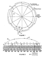
- FIGURES 1 and 2 illustrate twelve different stations on the bus.
- the circle 27 denoted in FIGURE 1 can be visualized as the token loop or token list if each of these twelve stations presently have the token passed to it.
- each station on that loop or list (sometimes also known as a token ring) has sequential synchronized access to the token.
- this list was in existence at a particular time, the token would be sequentially passed from station A to station B to station C, etc.
- stations G' and G" shown in FIGURE 1 stations that are not part of the token list as shown in FIGURE 1 and would have to get into the list in order to have periodic ownership of the token and thereby periodic control of the bus for initiating high level messages and for commanding other stations to transmit high level messages to them.
- the rules for a station becoming part of the token list, sometimes called patch in, are discussed further on in this detailed description.
- any one station that becomes inoperative in its ability to receive and pass the token in an error free manner cannot cause the overall communication system to fail.
- station J may for some reason become faulty - a typical example being that its receiver is no longer able to receive information and therefore it is unable to know when the token is being passed to it.
- This fault would be observed by the other stations since, as stated earlier, each station is able to hear all other stations because it constantly listens to the shared resource, namely the bus.
- the neighboring stations as detailed below, would patch out station J such as shown by chord segment 28 and thus the token would be passed from station I to station K, bypassing faulty station J. If at a later time station J became operational it could, through a demanding sequence, re - establish its presence on the token list, and thus the overall list would again have the shape shown by the circle 27 in FIGURE 1.
- each station which has token access capability embodies the same sets of rules which can be considered the formulation of states with the change of states being dependent upon how the rules are formulated in response to observed events (primitives), and in which the overall communication system operates in a synchronized fashion.
- the resulting synchronized serial bus is an underlying concept of the present communication system. Through it, the capability of a master-less communication system is achieved.
- arc 30 represents the token transfer between stations B, C and D.
- station owner C is the present token owner
- station B is the tail of the arc and was the previous token owner (referred to as the FROM)
- station D is the next token owner (referred to as the TO).
- T bus timeout
- a time period called T represents three-fourth a dead bus TIME OUT which each station initiates when a token is passed to a new owner.
- TIME OUT A time period called T represents three-fourth a dead bus TIME OUT which each station initiates when a token is passed to a new owner.
- stations B, C and D start their timers. If, after one-third times T station C has not initiated any transmission on the bus, the head of the arc (station D) assumes that something is wrong with station C and then proceeds to take the token; that is, station D assumes that station C has died with the token. Station D then, takes the token, insuring that the token is moved around the token list.
- station D If for some reason station D does not realize that station C has not generated a message within the one-third times T time period, the tail station, Station B, will after a time period equal to two-thirds times T, retake the token. If for some reason both the tail station, station B, and the head station, station D, do not take the token though station C is not operating properly, then after a time period equal to T (that is three-thirds times T), the present token owner, station C, if now healthy, retakes the token in an attempt to keep the token moving; that is it passes the token back to itself.
- each station realizes that something is wrong with the entire token passing scheme and thus reverts to the state known as initialization in which a token starter is found and a new token list is generated.
- FIGURES 2 and 3 Before describing the details of a particular communication system utilizing the present invention, reference should be made to FIGURES 2 and 3 to denote several other features of the present invention.
- a monitor 29 may be utilized and connected to the bus for monitoring the conditions of the bus and stations on the bus.
- the monitor does not need direct control of the bus nor the stations on the bus but is able to observe the messages on the bus and consequently the state of affairs with respect to the entire communication system.
- One such use for the monitor is to ascertain the number of stations presently in the token list as well as what the overall access time is between successive token passes to the same station.
- the monitor may also identify faulty stations due to such signals as their generation of ONLY ONE token passes to themselves as more fully described below.
- FIGURE 3 illustrates how the present invention can accommodate the situation where a communication system formally in the configuration of FIGURE 2 becomes faulty due to a break in the bus 20 such as at location 26.
- a break in the bus 20 such as at location 26.
- the token at the time of the break was resident in station A, B, C, D, E or F, that token would continue to be passed between those stations and thus would loop back as indicated by dotted line 35 (this assumes an initialization).
- Stations G-L at the same time would perceive the lack of a token and after the bus dead timeout expired, would go into an initialization sequence to reformulate a token list.
- the token list would be generated and a new token would be passed between stations G-L with the token being looped back from station L to G as shown by line 35'.
- the stations would immediately ascertain that illegal messages were being transmitted on the bus due to the fact that there would initially be two tokens present and thereby two stations initiating high level messages. Due to these "illegal" messages being generated, or by the station retry timers reaching maximum, the stations would enter what is known as a BUS IS DEAD state and re-initialize the token list thereby forming a single token list with stations A-L being in the token list if desired. Thus, the communication system would revert back to what is shown in FIGURE 2 with the loop back of the token going from station L to station A as shown by line 35". It is therefore readily seen that the present invention accommodates not only the condition of faulty stations, but also the condition of a faulty bus.
- each circle represents a state which any particular station can be in at any particular time. It should be realized that each station is in some state but that not all stations are in the same state at the same time. Thus, when reviewing FIGURES 17A-D, it must be realized that a particular station is moving from one state to another depending upon particular perceived events by that station and that simultaneously, other stations are moving between potentially different states due to their perceived events. Each station may indeed be observing different events at the same time. This is due in part to propagation delays on the bus; that is, that the propagation of information is limited to approximately .7 times the speed of light and therefore not all stations "see” the same information simultaneously. It is also due to noise which can exist on the bus.
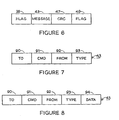
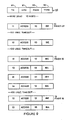
- the message format is shown in FIGURES 7 and 8 forming part of the overall data packet shown in FIGURE 6.
- the data packet transmitted on the bus comprises four parts: a first flag field 36, comprising the bit pattern 01111110, a message 43 comprising four or five bytes, a CRC field 47, comprising a 16 bit frame check sequence, and a second flag 49, comprising the same bit pattern as the first flag.
- the message formats are shbwn in FIGURES 7 and 8.
- the first byte 90 comprises the destination station address for the message, which in the preferred embodiment would be a number between 1 and 255. A zero in this byte represents a broadcast message to be potentially responded to by any station.
- the second byte 91 is the CMD field which is the high level data link command field which always transmits a value equal to C8 in hexadecimal format for access messages.
- the third byte 92 is the FROM byte and gives the address for the sending station.
- the fourth byte 93 is the TYPE byte and indicates the particular message being sent. These message types are described in Table 1.
- the fifth byte 94 shown in FIGURE 8 is for certain access messages ("who's next" and "load your TO FROM") where an address needs to be passed from one station to another.
- station A shown in FIGURE 1 is the current token owner (token .and baton are used synonymously in the figures and tables).
- the first step for passing the token is for station A to pass a token enable signal (signal BE, see Table 1) to its TO station; that is, station B.
- Station B would then respond with a token acknowledge signal ( B A) which when received by station A would cause station A to send the token signal (BT) to station B.
- Station B would become a token owner and station A would enter the watching your TO state (FIGURE 17D).
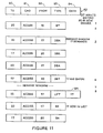
- Table 2 should be viewed with reference to FIGURE 10 wherein the steps denoted as one through eight in Table 2 are indicated along the right-hand portion of FIGURE 10. Similar step numbers appear for Tables 3-8 and corresponding FIGURES 11-15 and 9 respectively. It is thus seen by combination of Table 2 and FIGURE 10 that first the token owner (station 10) sends a token enable signal to his TO station of record (station 15). That is the present token owner knows the next station that is supposed to receive the token in the token list (FIGURE 1). It thus sends a signal to that token owner (through the unique addressing of each station) to tell that station that it is about to receive the token.
- the TO station responds with a token acknowledge signal.
- station A is the present token owner
- station B would be station A's TO.
- station B upon receiving the token enable signal generates a token acknowledge signal.
- Station A would then generate a token signal which in effect sends the token to station B.
- the new station owner will then listen for a period of time equal to 50 microseconds to allow potential demanders to signal it. This ability to allow demanders to interrupt the new token owner during the token pass provides for the ability of new stations to be patched into the token list.
- the next step in the token pass message sequence is that the new token owner (station 15) sends any high level data link control message the station might have queued for transmission in its data communication module to some other station and waits for a response if necessary.
- the overall time that a particular station owns the token is at least equal to some maximum period of time which is equal to the maximum propagation delay on the bus (time to go from one end of the bus to the other) plus the amount of time required for a station to receive a request for information, to assemble information and then proceed to transmit it (the response time of the receiving station for preparing and sending data).
- This overall time is typically two to ten milliseconds for a typical length bus of 15,000 feet.
- the frequency for data transfer on the bus is selected at 1.544 megahertz (a multiple of a standard communications frequency) which for the typical propagation speed of .7 times the speed of light for the bus, provides that the entire message transmitted by any station completely rides on the bus; that is, the amount of time given a station to send a message is such that discrete packets of the messages cannot individually ride on the bus simultaneously.
- the maximum amount of time that a station may own the bus varies depending upon the particular needs of the station.
- typical token ownership times would vary from 2 to 10 milliseconds. Due to the fact that each station has a maximum token ownership time and since the number of stations in the token list can be ascertained, the concept of a guaranteed access time is achieved.
- the stations respectively have a 10 millisecond, a 2 millisecond, a 3 millisecond and a 5 millisecond token ownership time respectively, there would be a 20 millisecond guarantee access time. That is, within 20 milliseconds each of the four stations would have ownership of the token if the token is being passed successfully.
- step 8 the access steps (steps 1 through 3) can in some circumstances be reduced to a single step; namely, a token pass as shown in step 8.
- a token pass as shown in step 8.
- the token pass message sequence can also be visualized with reference to FIGURES 17A-17D.
- station A to be the token owner
- station A is in the token owner state shown in FIGURE 17B.
- event 33 it goes into the HDLC master state. This is the state in which the station transmits and has returned to it high level data link messages over the bus. It is at this state that station A resides as it gets ready to pass the token to station B.
- station A enters the token passing state shown in FIGURE 17D.
- event 34 station A goes into the "WATCHING YOUR TO" state (FIGURE 17D) and if it observes that station B is active (that is that it has accepted the token), event 36, station A then enters the IN LIST state shown in FIGURE 17D. If station A in WATCHING YOUR TO state observes incorrect or no activity by station B, station A may receive the token and retransmit the token to station C.
- station B when station A receives the token, event 62, station B goes from the IN LIST state to the WATCHING ITS FROM state (see FIGURE 17D).
- station A completes its HDLC work, event 31, station B receives a token signal, event 32, and thus proceeds to the TOKEN OWNER state while station A completes the TOKEN PASSING state.
- This transfer from the WATCHING FROM state to the TOKEN OWNER state requires the handshaking as enumerated in Table 2 steps 1-3 or step 3 only depending upon the handshaking protocol utilized. Thus there is in essence a series of substates which are not shown in FIGURES 17A-D which take place when this particular event occurs.
- Station B if it receives a quiet demand window, event 33, similarly will enter the HDLC master state and proceed to transmit any high level messages which it may have queued in its transmit buffer in the communication module 25 (FIGURE 2).
- station B Upon completion of the transmission of its messages or upon expiration of its token ownership time slot, station B then attempts to pass the token to its TO station, namely station C, and if a successful token pass occurs, event 34, station B enters the WATCHING YOUR TO state.
- station B When in the WATCHING YOUR TO state, station B if it notices that station C becomes active within a time period less than one-third the bus timeout period (1/3 T) known as message timeout, 100 u sec will realize that station C has not only received the token but has become active (the event your TO is active occurring, event 36) and then will proceed to move to the IN LIST state where it will reside until it again sees that station A has received the token. At that time, event 62, will be perceived and station B will enter the WATCHING FROM state to repeat the cycle.
- T bus timeout period
- Stations G' and G" would, since not part of the token list, be in the OUT OF LIST state (FIGURE 17A).
- token passing assumes that each station correctly receives the access messages from its FROM and TO stations, and that everything is working in a pristine error-free environment. Further on, discussion concerning the particular states-that are entered depending upon perceived errors by the stations is discussed. In order to obtain the desired communication system it is disclosed that the failure of any single station will not cause the overall communication system to stop functioning. Furthermore, the capability of the present invention provides for the reinitialization of a token list depending upon certain perceived events, including multiple station failures and failure in the communication medium, namely the bus.
- FIGURE 10 Before leaving the token pass description, reference should be made to FIGURE 10 to see the types of access messages which are communicated between the stations in the arc of control (namely the token owner station, its FROM and its TO stations) in order to fully appreciate the technique involved.
- the first access message which refers to station 10 sending a token enable signal to station 15. This is the first step in the token pass handshake protocol.
- the second message is also an access message in which station 15 sends back to station 10 a token acknowledge signal indicating that it has received the token enable signal correctly.
- the third message is again a token access message in which station 10 sends to station 15 the token and thus provides that station 15 will now have the token for its own use.
- Station 15 must wait and see a quiet demand window (event 33 in FIGURE 17B) which in this particular case is set at a 50 microsecond duration. If station 15 does not receive any message during the demand window, it perceives it as the quiet demand window 33 and then enters the HDLC master state which is shown as the fourth message. That is, at this point, station 15 has access to the bus by virtue of its ownership of the token. In this case, station 15 sends any message it desires to a slave station, which in this situation means a station that it desires to transmit data to and need not be a slave in the sense that it does not have token access capability in its own right. The message which it sends is described as link #, which simply means that station 15 is using a high level data link communication protocol of any type well-known in the art.
- the next message sequence is again an access message in which station 15 sends to its TO, namely station 20, a token enable signal.
- Station 20 if it receives this token enable signal correctly, proceeds to send to station 15 an access message of token acknowledge which in turn will cause station 15 to send the token to station 20 as shown in the penultimate message of FIGURE 10. Another demand window will occur in this case for station 20. If for some reason station 20 has no HDLC message to send, it would then proceed to a token pass of its own.
- the handshake protocol Between the stations for passing the token can be streamlined and thus provide for a quicker passing of the token.
- station 20 sends the token message to its TO station, station 25, without first sending the token enable signal (BE) nor requiring the receipt of the token acknowledge signal (BA) from station 25 before sending the token (signal BT).
- BE token enable signal
- BA token acknowledge signal
- This automatic adjustment in the handshaking protocol achieves a more efficient use of the bus by the interconnected stations.
- different stations on the bus may be using different token pass handshake protocols at the same time and it is only those stations which are passing the token between themselves in an error-free manner that switch to the faster or streamline token pass handshake protocol. Of course, if these stations perceive an error when in this high-speed token pass protocol, they will revert back to the more rigorous handshake as described in steps 1-3 of Table 2.
- the next access message sequence to be described is known as demanding.
- Demanding is the ability of a station which has token access capability to request entry into the token list or at least temporary entry onto the bus (owning the token for at least one pass).
- a station Prior to demanding such a station is in the out-of-list state (see FIGURE 17A). For some reason, this station (such as station G' shown in FIGURE 1), perceives the necessity to own the token either On a temporary or permanent basis.
- a station can enter in the out-of-list state due to the fact that upon power-up, event 39, it entered the NEW ONE state which after seeing a message, event 40, realizes that the communcation system is operating, that is, that the bus is active.
- station G' realizes that the token has passed over it, event 41 (FIGURE 17A) such as station G having the token and the token then passing to station H as shown in FIGURE 1, and if station G desires to be in the token list, station G' enters the demanding state (FIGURE 17A). At this point, station G' waits for the demand window and sends a demand token acknowledge message to the token owner that is observing the demand window, the token owner having an address closest to G' but higher than G' (this would be station H). The token owner (station H) then sends a demand token enable signal to the demander and the demander responds with a demand token acknowledge-signal.
- event 41 FIGURE 17A
- station G' waits for the demand window and sends a demand token acknowledge message to the token owner that is observing the demand window, the token owner having an address closest to G' but higher than G' (this would be station H).
- the token owner station H then sends a demand token enable signal to the demander and the demander responds with a demand token acknowledge-
- the demand token then passes to the demander causing the demander (station G') to become the token owner and enter the TOKEN OWNER state (FIGURE 17B).
- the "received demand token event 42 shown in FIGURE 17A actually represents a series of signals transmitted between the new token owner and the demanding station which upon proper handshake protocol (similar to the handshake protocol with respect to token passing between token owners in a list), results in a demand token being transferred from the new token owner, (station H) to the demander (station G').
- the new token owner station G' thus in turn listens to its demand window to see if anyone else is demanding the token.
- This situation is known as a multiple demand and can only occur when more than one station demanded the token from station H at the same time. However if that did occur, station G' would attempt to find the other demanding station which would have an address sequentially lower than that of G' and pass the token to this station as will be more fully described below with respect to the multiple demander situation.
- the new station owner (G') receives a quiet demand window, event 33, it informs its predecessor station (station G) to "load its TO” with the address of G' and informs its station (H) with a "load your from” with the address of G' and thus patches in its address into the token list.
- G' knows its own TO station (namely station H) and thus the list is patched with the correction of station H's information as to its FROM station (namely G') being substituted for its previous FROM station G.
- Table 3 in combination with FIGURE 11 goes through a detailed explanation of the demanding message sequence. Thus there are 8 steps shown in Table 3 and corresponding FIGURE 11.
- step 1 station 20 receives the token from station 15 in a token access message.
- Station 17 however wishes to become part of the token list and since it resides at an address between station 15 and 20, it demands access when station 20 receives demand.
- step 3 shows station 17 issuing a demand token acknowledge signal to station 20.
- Station 20 at step 4 then sends a demand token enable signal to station 17, which at step 5 sends a demand token acknowledge signal to station 20.
- Station 20 then sends the demand token to station 17 at step 6.
- steps 1-6 for passing the demander token are all access messages.
- Station 17 then has its own demand window (for only seeing noise on the bus if station 17 was the sole demander) and if this window is quiet (no noise) it sends a LOAD YOUR TO signal to the predecessor station from step 21, namely station 15. This 5is thus a five byte access message since the fifth byte tells station 15 that its TO station is now station 17 rather than 20.
- Station 17 also sends a "load your from” signal to the next station (20). This is also a five byte access message.
- station 17 after its HDLC messages are completed or after its token ownership timeout has occurred, sends a token enable signal to its TO station, namely station 20.
- Station 20 then sends a token acknowledge signal to station 17 to initiate the token pass to station 20.
- station 20 realizes that its FROM station is no longer station 15 but station 17 and thus the patch in of station 17 into the token list is completed.
- event 45 Upon receiving a demand from a demander, event 45, it enters the PASSING DEMAND TOKEN state. If a successful pass to the demander occurs, event 46, it enters the WATCHING DEMANDER state where, if the demander becomes active, event 48 causes the former token owner to enter the WATCHING FROM state. While in the WATCHING FROM state it in essence watches the demander which has received the token. If a one-third T timeout occurs, event 53 -that is that the demander has not transmitted on the bus within a prescribed period of time -- the former token owner enters the token passing state to pass the token to its TO station.
- event 45 if the token owner sees a demand, event 45, it enters the PASSING DEMAND TOKEN state. If instead of receiving a successful pass to the demander an unsuccessful pass to the demander occurs, event 57, the token owner instead of passing the token to the demander will instead enter the HDLC MASTER state. Here it issues any high level data link messages which it may have queued in its data communication module.
- station 17 could equally have demanded the token from station 20 without requiring entry into the token list. In this situation, station 17 would be known as a temporary demander and once it received the token from station 20 would not send the load your TO signal (step 8) to station 15 but would leave station 15 with its TO address equal to that of station 20. Consequently on the next pass of the token, station 15 would pass the token to station 20 leaving station 17 out of the token list.
- station H in FIGURE 1 receives the token from station G
- station G' and some other station, such as station G'' may simultaneously demand the token from station H.
- the token owner when in the token owner state shown in FIGURE 17 B receives a noisy demand window, event 44, instead of a clean demand window, event 33.
- station H instead of station H going to the PASSING DEMAND TOKEN state, shown in FIGURE 17B, it would enter the RUNNING DEMAND SEARCH state shown in FIGURE 17B. If when in this state a successful demand search is completed, event 50, station H would enter the PASSING DEMAND state.
- event 46 Upon successful passing to the demander, event 46, station H would enter the WATCHING DEMANDER state which if the demander becomes active, event 48, would cause station H to enter the WATCHING FROM state. Station H would then be able to become another token owner upon receiving the token enable signal from the demander.
- a successful demand search, event 50 causes station H to proceed through the states which it would have proceeded through had it only received a single demand during the demander window. If however station H after receiving a noisy demand window, event 44, then performs an unsuccessful demand search, event 52, it will instead revert to the HDLC master state, and thus continue to own the token and send out any HDLC messages which it has queued in its data communication buffer.
- FIGURE 1 indicates that two or more token masters, that is stations which have token access capability but are in the OUT OF LIST state (see FIGURE 17A), decide to demand the token. The token is then seen as passing over these two stations, event 41.
- station 15 is the present token owner sending the token to station 20. Since since stations 17 and 18 are the stations which want the token, and since station 20 is the new token owner, it has a demand window upon receipt of the token. Thus during the demand window, stations 17 and 18 transmit their demand token acknowledge message to token owner 20.
- stations 17 and 18 transmit their token acknowledge messages at the same time, the modem at station 20 merely perceives energy on the bus which is interpreted by station 20 as a noisy demand window, event 44, forcing station 20 to enter the running demand search state (FIGURE 17B).
- step 4 has occurred and step 5 results where station 20 searches for demanders.
- a second nechanism embodies searching for addresses of stations between it and its FROM (namely station 15). It thus sends a demand token enable signal to station 19 in its search down (step 5). No response is received for 100 microseconds (two times the demand window) and thus station 20 perceives that station 19 is not a demander. It thus sends a demand token enable signal to station 18 and then finds station 18 responding with a demand token acknowledge signal. Station 20 then sends a demand token signal (DBT) to station 18 which gives station 18 the token. Station 18 then has a demand window at which time station 17, one of the original demanders, sends a demand token acknowledge signal to station 18 requesting the token. This corresponds to step 7 of Table 4.
- DBT demand token signal
- Station 18 then sends a demand token signal to station L7, thus passing the token to station 17.
- station 17 would send a LOAD YOUR TO signal to station 15 since station 17 is the lowest address station of the new token masters. This corresponds to step 8 in FIGURE 11.
- station 15 realizes that station 17 is its new TO station rather than station 20.
- Station 17 will then proceed to pass the token to station 18 which will record its proper FROM and TO stations and subsequently station 18 will pass the token to station 20 to complete the patching of stations 17 and 18 into the token list.
- Another commonly incurred message sequence of the communication system according to the present invention is called WHO'S NEXT.
- the station which has the token sends a token enable signal (signal BE) to its TO station of record, but gets no response from the TO station.
- This event should be distinguished from the situation where the present token owner sends the token to its TO station, the TO station properly receives the token through the token passing handshaking protocol (whichever one is used) and then fails to transmit a HDLC message within a prescribed period, and also fails to pass the token to its TO station.
- the token owner sends a token enable signal to its TO station and the TO station does not acknowledge that signal.
- the present token owner will retry to pass the token some number of times, typically three times, and if unsuccessful in passing the token to its TO station, the present token owner will assume that its TO station is faulty and will therefore pass the token to the next station in the token list. The result is that the faulty TO station will be patched out of the token list and will only be able to come back into the token list if it is operating properly and goes through a successful demander message sequence such as described above.
- station A (FIGURE 1) is in the token passing state, and if it is unable to pass to station B, the unsuccessful token pass attempt, event 54, would have occurred.
- Station A would then enter the WHO'S NEXT state which if an I'M NEXT RECEIVED signal, event 56, is received by station A from another station in the token list (such as station C which is the next sequential station to receive the token after station B) causes station A to go back to the TOKEN PASSING state. Station A will then pass the token to station C rather than to station B. If however station B does not receive an I'M NEXT RECEIVED event it will determine that there is no NEXT station found and thus an unsuccessful pass to I'M NEXT would have occurred, event 58.
- station A will cause station A to enter the BUS IS DEAD state (FIGURE 17C) which will in turn cause the overall communication system to enter an initialization message sequence which will be described later on.
- station A could enter the passing initialization search state (FIGURE 17A) if the states are reconfigured that way. This change in the rules which therefore gives rise to different states occurring upon different perceived events by each station is an example of the versatility of the underlying concepts embodied in the present invention.
- Table 5 in conjunction with FIGURE 13 details the specific messages generated in the WHO'S NEXT message sequence. All of the message types are access messages although some are of the five byte format.
- the master station that is the station which presently owns the token, sends a token enable signal (BE) to its TO of record but gets no response.
- BE token enable signal
- station 10 sends a bus enable signal to its TO station, namely station 15.
- Station 15 does not respond with a token acknowledge signal within a 100 microsecond timeout and thus station 10 again sends a token enable signal to station 15.
- station 15 will then send a broadcast WHO'S NEXT signal containing the address of the unanswering station (station 15).
- This WHO'S NEXT signal is shown in FIGURE 3 as a five-byte signal in which the TO address is now a broadcast address because it must be received by all stations on the bus. This address is arbitrarily given the address of 0 as described earlier with respect to message formats (see Table 1). All stations receive this access message and the station which had station 15 as its FROM station will know that something is wrong with station 15 and determine therefore that it is the WHO'S NEXT.
- station 20 which normally receives the token from station 15, determines that it is the next station and therefore sends an IT'S NEXT signal (IN) to station 10, again indicating that station 15 was station 20's FROM station.
- Station 10 proceeds to step 5 by sending a token enable signal to station 20 with station 20 acknowledging this signal with a token acknowledge signal and then station 10 passes the token to station 20.
- Station 15 is thus patched out of the token list.
- Token Pickup Another commonly occurring message sequence is known as Token Pickup.
- a token is passed from one station to its TO station and then after the token has passed the TO station dies; that is, it fails to transmit a HDLC message or fails to pass the token to its TO station.
- the state map shows this in FIGURE 17B where if we assume station A (shown in FIGURE 1) has the token it would first be in the TOKEN PASSING state. Upon a successful token pass, event 34, it would enter the WATCHING YOUR TO state. If an active TO is perceived, that is that the TO station has taken the token and has acted with it by either sending a HDLC message or by passing the token to its TO station, then station A would enter the IN LIST state.
- station A would retry to pass the token to station B and if unsuccessful (a situation where station B is defective) it would enter the SENDING WHO'S NEXT state and proceed in a manner described above with respect to the WHO'S NEXT message sequence.
- station A will retake the token when a time period equal to two-third (T) occurs where T is the period of time by which the present token owner will retake the token and use it for its own purposes.
- T is selected at 7.5 milliseconds and thus two-thirds T equals 5.0 milliseconds.
- Table 6 in combination with FIGURE 14 details the Token Pickup message sequence.
- four steps relate to the Token Pickup message sequence.
- the first step is where after passing the token, the station watches the bus to see that the new owner uses it. If the new owner has not seen the token after the token pass signal is generated (due to noise on the bus) it would not use the token. This would be perceived by the previous token owner as the present token owner dying with the token.
- the present token owner may alternatively actually die with the token; that is, after receiving it the station malfunctions preventing it from transmitting HDLC messages or passing the token to its TO station.
- the previous token owner After a timeout which is typically 5 milliseconds without the previous token owner seeing energy on the bus, (which would represent the new token owner not using the token) the previous token owner will retry to pass the token, and if unsuccessful, will determine an unsuccessful token pass attempt and initiate the WHO'S NEXT message sequence.
- FIGURE 14 thus shows that station 10 passes the token to station 15. However, station 15 dies with the token after a 5 millisecond timeout without seeing energy on the bus (or wire). Station 10 then sends a token enable signal back to station 15 and if after a 100 microsecond timeout a token acknowledge is not received from station 15 will retry to send the token by reinitiating the token enable signal to station 15 for a total of three times. After that, station 10 enters the WHO'S NEXT state and proceeds in a manner described above and shown in FIGURE 13. Thus a WHO'S NEXT broadcast signal is transmitted by station 10 and if station 20 was the station next to receive the token after station 15, station 20 would send an I'M NEXT signal (IN). Station 10 would then proceed to initiate a token pass handshake with station 20 by sending a token enable signal to station 20.
- a WHO'S NEXT broadcast signal is transmitted by station 10 and if station 20 was the station next to receive the token after station 15, station 20 would send an I'M
- Token Pickup Another common message sequence is known as Token Pickup in which a present token owner's FROM dies with the token.
- station A is the token owner when it receives the token from station L
- station B the next station to receive the token, records station A receiving the token by going from the IN LIST state to the WATCHING FROM state due to its observence of the token sent to its FROM, event 62 (FIGURE 17D).
- its FROM station station A
- Station B will perceive a timeout, and will thus enter the TOKEN PASSING state.
- Station B will then attempt to pass the token to its next (TO) station, which would be station C.
- station B does not enter the HDLC MASTER state, but merely is a conduit for passing the token from itself to the next station to keep the token moving.
- the token will return to station B on the next pass at which time it will enter the HDLC MASTER state due to the fact that by that time station A will be patched out of the token list. That is on the next go-around presuming that station A is still faulty, station L will not be able to pass the token to station A and will then enter a WHO'S NEXT message sequence at which time station B will indicate that it is next and station L will pass the token to station B, patching out station A.
- Table 7 in combination with FIGURE 15 gives the details of the steps comprising the token pickup message sequence for the situation where a station's FROM station dies with the token.
- the first step performed is that a station realizes that its FROM station has received the token.
- the second step is that the station realizing its FROM has received the token also realizes that a one-third T timeout has occurred without energy being transmitted onto the bus by the token owner. This time is typically 2.5 milliseconds.
- the next step is for the unit that next receives the token to pick up the token and pass it to its TO station (that is for example where station B picks up the token and passes it to station C).
- FIGURE 15 illustrates this in terms of the messages sent onto the bus.
- station 10 first sends the token to station 15 by a token pass (BT) signal.
- Station 15 is on the bus and would normally transmit high level HDLC messages but for some reason does not do so. This is seen as a lack of energy on the bus by station 20, the station to next receive the token from station 15.
- Station 20 then takes the token and sends a token enable signal to its TO station which happens to be station 25.
- Station 25 acknowledges this token enable signal by generating a token acknowledge signal.
- the handshaking protocol would continue and the token would pass to station 25.
- Such a situation could be where the present token owner dies with the token and for some reason the station to which it would next pass the token (the station in the WATCHING FROM state, see FIGURE 17D) does not respond to the one-third T timeout and thus does not enter the token passing state).
- the station which sent the token to the present token owner may for some reason not perceive that the present token owner is failing to utilize the token (that is it perceives the two-thirds T event).
- the present station may truly be defective and not pickup the token after three-thirds T timeout has occurred. In this case, a four-third T timeout will occur for properly operating stations. This timeout is called the BUS IS DEAD timeout, event 64, which will cause the IN LIST and OUT OF LIST state stations to enter the BUS IS DEAD state (see FIGURES 17C and 17D).
- a BUS IS DEAD state can also occur when an illegal message, event 59, is seen by the token owner. Such an illegal message would typically occur where a broken bus, as shown in FIGURE 3, is repaired, as shown in FIGURE 2. Then two token owners would initially exist, creating illegal messages to appear on the bus. The token owners would then each enter the WAIT state, and if a message, event 61, is not seen within a period of time (such as four-thirds T), it will enter the BUS IS DEAD state. .
- Bus Rebuild Timeout event 68
- a Bus Rebuild Timeout event 68
- each station will perform its respective Bus Rebuild Timeout, but only the first one which times out enters the PASSING INITIALIZATION or SEARCH state.
- other techniques such as generating a random number timeout, for determining the station to start the initialization search could be utilized, especially when thousands of stations are part of the communication system.
- the first station in the SEARCH state then does a linear search starting with its address plus one to search for the next highest address station on the bus.
- the initialization sequence Rebuild Timeout, event 68 is preferably chosen to equal the address of the station times 100 microseconds.
- the first station entering the SEARCH state sends out token initialization signals to sequentially higher addresses.
- the successful initialization token pass, event 70 causes the first station to enter the IN LIST state.
- the search continues, looping around all 255 stations as described in the preferred embodiment, until the originator of the search is found.
- a special bit is stored by that station which is known as the SEARCH STOP bit. This bit is set by the station first entering the passing initialization state, and thus when the initialization search loops back to this station, it knows that the initialization sequence has been completed, and that normal token passing can begin.
- This SEARCH stop bit is stored in the access module 24 along with the FROM and TO station addresses.
- station 10 is the first station to TIMEOUT through event 68.
- Station 10 then accesses station 11. After a 100 microsecond timeout of not receiving a token acknowledge signal from station 11, station 10 accesses station 12 and will continue to do so until it finds a station which generates a token acknowledge signal within the 100 microsecond time period.
- station 13 sends such a signal to station 10.
- Station 10 then sends an initialization token to station 13 (the IBT signal).
- Station 13 then resumes the search, sending out initialization token signals to its sequentially higher address stations until receiving an initialization token acknowledgement signal, which in this example occurs from station 15.
- a successful initialization pass event 70 is perceived as changing the state of that station from the passing initialization state to the IN list state.
- station 10 After station 10 successfully passes the token to station 13, station 10 enters the IN LIST state; that is, it is one of the stations which is going to be part of the token list. Such a state is then obtained for station 13 when station 15 is found. This continues for all the stations which send an initialization token acknowledge signal to the station performing the initialization search.
- FIGURE 16 shows the message format for such a token pass.
- the Only One Timeout is equal to a relatively large multiple of the DEAD BUS TIMEOUT and is typically 160 milliseconds for a BUS DEAD TIMEOUT of 10 milliseconds. Regardless of the multiple chosen, this timeout is relatively long with respect to the DEAD BUS TIMEOUT. The reason is to prevent a station in the ONLY ONE state from interferring with other stations on the bus in a situation where the station in the ONLY ONE state is there not because it is truly the only one attempting to communicate on the bus, but because it perceives itself as the only one while in actuality it is not. This latter situation can occur where the station in the ONLY ONE state has a bad receiver and thus cannot hear other stations on the bus, and consequently believes itself to be the only one. In such a situation, if the station in the ONLY ONE state were able to frequently pass tokens on the bus to itself, this could substantially interfer with the other stations on the bus. Thus, the Only One Timeout restricts the frequency of such token passes.
- the initialization message sequence is critical to building the token list after an initial POWER UP and also to rebuild the list when multiple errors occur, causing the stations on the bus to enter the BUS IS DEAD state. If the station entering the ONLY ONE state, due to an unsuccessful initialization search event 71, is truly the ONLY ONE station, then it will remain in this state until either some other station starts to communicate on the bus through an initialization search and finds this station in the ONLY ONE state or alternatively when the station in the ONLY ONE state generates a token pass to itself which is heard by other stations on the bus indicating that some other station (namely the one in the ONLY ONE state) is alive on the bus.
- Passing the token to itself indicates to the stations on the bus and in particular, to a monitor 29 (see FIGURES 2 and 5) connected to the bus, that a station is on the bus which is operating improperly.
- the monitor can therefore locate the faulty station(s) so that their maintenance can be instigated.
- the monitor can also be used for other purposes, such as determining how many stations on the bus are in the token list and for what percentage of time HDLC messages are being transmitted.
- Tables 9-1 3 detail the state variable definitions, the byte variable definitions, the time usages, as well as the responses to noise, illogical messages, and interrupt usages respectively. These tables give further details for implementing the access mechanism of a local area network communication system according to the present invention.
- the hardware for forming the access module is preferably the Intel Corporation 8051 microprocessor. Since the bus uses a serial data transmission while the microprocessor uses parallel data, a Motorola 68B54 serial/parallel conversion can be used.
- the data communication module 25 can use the Intel Corporation 8088 microprocessor chip.
- each station has at least one timer 65 (part of the 8051, see FIGURES 2 and 5) for generating the tine periods sensed by the respective stations as the various perceived events described above.
- FIGURES 17A-17D results in a communication system embodying the underlying principals of the present invention -- including the concept of the station presently having the token knowing from whom it receives the token as well as to whom it will next pass the token -- it is readily apparent that other formulations of the fundamental rules of passing the token can be structured so as to give rise to different ways for the same states shown in FIGURES 17A-17 D to occur depending upon perceived events or for some different states to occur.
- the underlying concept of each station embodying the same sets of rules for recognizing particular events (except for slave stations 22') and what to do upon perception of those events is key to the present invention so that each station has potential token access capability.
Landscapes
- Engineering & Computer Science (AREA)
- Computer Networks & Wireless Communication (AREA)
- Signal Processing (AREA)
- Small-Scale Networks (AREA)
- Computer And Data Communications (AREA)
- Data Exchanges In Wide-Area Networks (AREA)
Applications Claiming Priority (2)
| Application Number | Priority Date | Filing Date | Title |
|---|---|---|---|
| US06/241,688 US4491946A (en) | 1981-03-09 | 1981-03-09 | Multi-station token pass communication system |
| US241688 | 1981-03-09 |
Related Parent Applications (3)
| Application Number | Title | Priority Date | Filing Date |
|---|---|---|---|
| EP82301042A Division-Into EP0060067B1 (fr) | 1981-03-09 | 1982-03-02 | Système de communication à plusieurs stations avec transfert d'un signal "droit à émettre" |
| EP82301042A Division EP0060067B1 (fr) | 1981-03-09 | 1982-03-02 | Système de communication à plusieurs stations avec transfert d'un signal "droit à émettre" |
| EP82301042.6 Division | 1982-03-02 |
Publications (2)
| Publication Number | Publication Date |
|---|---|
| EP0139916A2 true EP0139916A2 (fr) | 1985-05-08 |
| EP0139916A3 EP0139916A3 (fr) | 1985-06-05 |
Family
ID=22911760
Family Applications (2)
| Application Number | Title | Priority Date | Filing Date |
|---|---|---|---|
| EP82301042A Expired EP0060067B1 (fr) | 1981-03-09 | 1982-03-02 | Système de communication à plusieurs stations avec transfert d'un signal "droit à émettre" |
| EP84109277A Withdrawn EP0139916A3 (fr) | 1981-03-09 | 1982-03-02 | Initialisation dans un système de communication à plusieurs stations avec transfert d'un signal "droit à émette" |
Family Applications Before (1)
| Application Number | Title | Priority Date | Filing Date |
|---|---|---|---|
| EP82301042A Expired EP0060067B1 (fr) | 1981-03-09 | 1982-03-02 | Système de communication à plusieurs stations avec transfert d'un signal "droit à émettre" |
Country Status (6)
| Country | Link |
|---|---|
| US (1) | US4491946A (fr) |
| EP (2) | EP0060067B1 (fr) |
| JP (2) | JPH0620203B2 (fr) |
| AT (1) | ATE27520T1 (fr) |
| CA (1) | CA1191921A (fr) |
| DE (1) | DE3276462D1 (fr) |
Cited By (5)
| Publication number | Priority date | Publication date | Assignee | Title |
|---|---|---|---|---|
| EP0435037A2 (fr) * | 1989-12-28 | 1991-07-03 | Allen-Bradley Company, Inc. | Réseau industriel à passage de jeton du type maître-esclave |
| EP0439331A2 (fr) * | 1990-01-26 | 1991-07-31 | Honeywell Inc. | Réseau de communication multi-nodal avec responsabilité coordonnée des noeuds pour les fonctions globales |
| EP0604668A1 (fr) * | 1992-08-28 | 1994-07-06 | Siemens Aktiengesellschaft | Boucle logique avec surveillance du temps de rotation |
| EP0604669A1 (fr) * | 1992-08-28 | 1994-07-06 | Siemens Aktiengesellschaft | Système de bus avec surveillance de réponses des participants |
| EP3016351A1 (fr) * | 2014-11-03 | 2016-05-04 | Pepperl + Fuchs GmbH | Procédé pour faire fonctionner un système de capteur avec plusieurs dispositifs de capteur, dispositif capteur, installation de capteur et système de capteur |
Families Citing this family (125)
| Publication number | Priority date | Publication date | Assignee | Title |
|---|---|---|---|---|
| US4439856A (en) * | 1982-02-24 | 1984-03-27 | General Electric Company | Bimodal bus accessing system |
| US4593280A (en) * | 1982-03-05 | 1986-06-03 | Burroughs Corporation | Write token regeneration in a timed token ring |
| DE3376590D1 (en) * | 1982-04-28 | 1988-06-16 | Int Computers Ltd | Data processing system |
| DE3268099D1 (en) * | 1982-06-15 | 1986-02-06 | Ibm | Method and apparatus for controlling access to a communication network |
| CA1226638A (fr) * | 1982-08-19 | 1987-09-08 | Mitsuji Takao | Transmission de donnees |
| US4575846A (en) * | 1982-10-08 | 1986-03-11 | Canon Kabushiki Kaisha | Data communication system |
| US4590468A (en) * | 1983-03-10 | 1986-05-20 | Western Digital Corporation | Token access controller protocol and architecture |
| JPS59188256A (ja) * | 1983-04-11 | 1984-10-25 | Hitachi Ltd | ル−プ伝送システムの伝送方法 |
| GB8310821D0 (en) * | 1983-04-21 | 1983-05-25 | Int Computers Ltd | Data communication systems |
| GB2140180A (en) * | 1983-05-20 | 1984-11-21 | Sony Corp | Remote control systems |
| US4551721A (en) * | 1983-10-07 | 1985-11-05 | Honeywell Inc. | Method for initializing a token-passing local-area network |
| FR2556536B1 (fr) * | 1983-12-09 | 1990-02-02 | Inf Milit Spatiale Aeronaut | Procede de communication asynchrone en anneau d'informations numeriques, et dispositif de traitement reparti utilisant ce procede |
| US4581734A (en) * | 1984-02-14 | 1986-04-08 | Rosemount Inc. | Multipriority communication system |
| US4725834A (en) * | 1984-02-27 | 1988-02-16 | American Telephone And Telegraph Company, At&T Bell Laboratories | Reliable broadcast protocol for a token passing bus network |
| JPS60206341A (ja) * | 1984-03-30 | 1985-10-17 | Yokogawa Hokushin Electric Corp | 通信制御方法 |
| US4785449A (en) * | 1984-05-21 | 1988-11-15 | Canon Kabushiki Kaisha | Network system for data transmission among plural communications stations connected to a communication medium |
| JPS6133045A (ja) * | 1984-07-25 | 1986-02-15 | Toshiji Hasegawa | ネツトワ−ク優先度決定方式 |
| US4707830A (en) * | 1985-03-05 | 1987-11-17 | General Electric Company | Token passing LAN using a plurality of tokens |
| US4649535A (en) * | 1985-05-13 | 1987-03-10 | General Electric Company | Method and apparatus for maintaining a dynamic logical ring in a token passing LAN |
| US4642607A (en) * | 1985-08-06 | 1987-02-10 | National Semiconductor Corporation | Power line carrier communications system transformer bridge |
| US4667323A (en) * | 1985-09-03 | 1987-05-19 | Allen-Bradley Company, Inc. | Industrialized token passing network |
| JPS62120141A (ja) * | 1985-11-20 | 1987-06-01 | Mitsubishi Electric Corp | ト−クン伝送方式 |
| US4745598A (en) * | 1985-11-27 | 1988-05-17 | General Electric Company | Method and apparatus for maintaining a dynamic logical ring in a token passing LAN |
| US4682326A (en) * | 1985-11-27 | 1987-07-21 | General Electric Company | Method and apparatus for maintaining a dynamic logical ring in a token passing lan |
| US4674086A (en) * | 1985-12-16 | 1987-06-16 | Texas Instruments Incorporated | Token ring access control protocol circuit |
| US4736368A (en) * | 1985-12-16 | 1988-04-05 | Texas Instruments Incorporated | Priority token protocol circuit for a token ring local area network adaptor |
| US4789982A (en) * | 1986-01-27 | 1988-12-06 | Codenoll Technology Corporation | Method for implementing a token passing ring network on a bus network |
| US4747100A (en) * | 1986-08-11 | 1988-05-24 | Allen-Bradley Company, Inc. | Token passing network utilizing active node table |
| US4766530A (en) * | 1986-11-24 | 1988-08-23 | Westinghouse Electric Corp. | Token passing scheme for a predetermined configuration local area network |
| US5241627A (en) * | 1987-04-09 | 1993-08-31 | Tandem Computers Incorporated | Automatic processor module determination for multiprocessor systems for determining a value indicating the number of processors |
| US5025491A (en) * | 1988-06-23 | 1991-06-18 | The Mitre Corporation | Dynamic address binding in communication networks |
| US5243335A (en) * | 1988-08-10 | 1993-09-07 | Omron Tateisi Electronics Co. | Local area network system |
| US4864563A (en) * | 1989-01-09 | 1989-09-05 | E-Systems, Inc. | Method for establishing and maintaining a nodal network in a communication system |
| US4949337A (en) * | 1989-01-30 | 1990-08-14 | Honeywell Inc. | Token passing communication network including a node which maintains and transmits a list specifying the order in which the token is passed |
| NL193573C (nl) * | 1989-04-04 | 2000-02-02 | Yokogawa Electric Corp | Duplex-computerstelsel. |
| US4926418A (en) * | 1989-04-11 | 1990-05-15 | International Business Machines Corporation | Fairness algorithm for full-duplex buffer insertion ring |
| US5155726A (en) * | 1990-01-22 | 1992-10-13 | Digital Equipment Corporation | Station-to-station full duplex communication in a token ring local area network |
| JPH04332065A (ja) * | 1991-05-08 | 1992-11-19 | Matsushita Electric Ind Co Ltd | データ転送方法 |
| US5638055A (en) * | 1992-03-26 | 1997-06-10 | Motorola, Inc. | Communication resource allocation by interrupt status |
| US6272559B1 (en) | 1997-10-15 | 2001-08-07 | Sun Microsystems, Inc. | Deferred reconstruction of objects and remote loading for event notification in a distributed system |
| US6182083B1 (en) | 1997-11-17 | 2001-01-30 | Sun Microsystems, Inc. | Method and system for multi-entry and multi-template matching in a database |
| US6185611B1 (en) | 1998-03-20 | 2001-02-06 | Sun Microsystem, Inc. | Dynamic lookup service in a distributed system |
| US6938263B2 (en) | 1996-04-23 | 2005-08-30 | Sun Microsystems, Inc. | System and method for facilitating dynamic loading of “stub” information to enable a program operating in one address space to invoke processing of a remote method or procedure in another address space |
| US6393497B1 (en) * | 1998-03-20 | 2002-05-21 | Sun Microsystems, Inc. | Downloadable smart proxies for performing processing associated with a remote procedure call in a distributed system |
| US6421704B1 (en) | 1998-03-20 | 2002-07-16 | Sun Microsystems, Inc. | Method, apparatus, and product for leasing of group membership in a distributed system |
| US6708171B1 (en) | 1996-04-23 | 2004-03-16 | Sun Microsystems, Inc. | Network proxy |
| US6226746B1 (en) | 1998-03-20 | 2001-05-01 | Sun Microsystems, Inc. | Stack-based system and method to combine security requirements of methods |
| US6832223B1 (en) | 1996-04-23 | 2004-12-14 | Sun Microsystems, Inc. | Method and system for facilitating access to a lookup service |
| US6560656B1 (en) | 1998-02-26 | 2003-05-06 | Sun Microsystems, Inc. | Apparatus and method for providing downloadable code for use in communicating with a device in a distributed system |
| US6446070B1 (en) * | 1998-02-26 | 2002-09-03 | Sun Microsystems, Inc. | Method and apparatus for dynamic distributed computing over a network |
| US6598094B1 (en) | 1998-03-20 | 2003-07-22 | Sun Microsystems, Inc. | Method and apparatus for determining status of remote objects in a distributed system |
| US6282652B1 (en) | 1998-02-26 | 2001-08-28 | Sun Microsystems, Inc. | System for separately designating security requirements for methods invoked on a computer |
| US6237024B1 (en) | 1998-03-20 | 2001-05-22 | Sun Microsystem, Inc. | Method and apparatus for the suspension and continuation of remote processes |
| US6487607B1 (en) | 1998-02-26 | 2002-11-26 | Sun Microsystems, Inc. | Methods and apparatus for remote method invocation |
| US6438614B2 (en) | 1998-02-26 | 2002-08-20 | Sun Microsystems, Inc. | Polymorphic token based control |
| US6578044B1 (en) | 1997-11-17 | 2003-06-10 | Sun Microsystems, Inc. | Method and system for typesafe attribute matching |
| US6138238A (en) | 1997-12-11 | 2000-10-24 | Sun Microsystems, Inc. | Stack-based access control using code and executor identifiers |
| US6247026B1 (en) | 1996-10-11 | 2001-06-12 | Sun Microsystems, Inc. | Method, apparatus, and product for leasing of delegation certificates in a distributed system |
| US6466947B2 (en) | 1998-03-20 | 2002-10-15 | Sun Microsystems, Inc. | Apparatus and method for dynamically verifying information in a distributed system |
| US6463446B1 (en) | 1998-02-26 | 2002-10-08 | Sun Microsystems, Inc. | Method and apparatus for transporting behavior in an event-based distributed system |
| US6188675B1 (en) * | 1996-08-23 | 2001-02-13 | International Business Machines Corporation | System and method for self-identifying and configuring the nodes of a network |
| US5832529A (en) | 1996-10-11 | 1998-11-03 | Sun Microsystems, Inc. | Methods, apparatus, and product for distributed garbage collection |
| US6728737B2 (en) | 1996-10-11 | 2004-04-27 | Sun Microsystems, Inc. | Method and system for leasing storage |
| US6237009B1 (en) | 1996-10-11 | 2001-05-22 | Sun Microsystems, Inc. | Lease renewal service |
| US6253256B1 (en) | 1997-10-15 | 2001-06-26 | Sun Microsystems, Inc. | Deferred reconstruction of objects and remote loading in a distributed system |
| US6957427B1 (en) | 1997-10-15 | 2005-10-18 | Sun Microsystems, Inc. | Remote object activation in a distributed system |
| KR20010033457A (ko) * | 1997-12-15 | 2001-04-25 | 인텔로지스 | 전력회선 교환 프로토콜을 위한 방법 및 장치 |
| US6604127B2 (en) | 1998-03-20 | 2003-08-05 | Brian T. Murphy | Dynamic lookup service in distributed system |
| WO1999044133A2 (fr) | 1998-02-26 | 1999-09-02 | Sun Microsystems, Inc. | Procede et systeme d'identification de procede a distance au moyen de hachages deterministes |
| GB9902000D0 (en) | 1999-01-30 | 1999-03-17 | Delta Biotechnology Ltd | Process |
| US6901518B1 (en) | 1999-04-08 | 2005-05-31 | Sun Microsystems, Inc. | Method and system for establishing trust in downloaded proxy code |
| US6877163B1 (en) | 1999-06-14 | 2005-04-05 | Sun Microsystems, Inc. | Method and system for dynamic proxy classes |
| US6845393B1 (en) | 1999-06-14 | 2005-01-18 | Sun Microsystems, Inc. | Lookup discovery service in a distributed system having a plurality of lookup services each with associated characteristics and services |
| US7310670B1 (en) * | 2000-04-25 | 2007-12-18 | Thomson Licensing S.A. | Multi-channel power line exchange protocol |
| US6789077B1 (en) | 2000-05-09 | 2004-09-07 | Sun Microsystems, Inc. | Mechanism and apparatus for web-based searching of URI-addressable repositories in a distributed computing environment |
| US7260543B1 (en) | 2000-05-09 | 2007-08-21 | Sun Microsystems, Inc. | Automatic lease renewal with message gates in a distributed computing environment |
| US7080078B1 (en) | 2000-05-09 | 2006-07-18 | Sun Microsystems, Inc. | Mechanism and apparatus for URI-addressable repositories of service advertisements and other content in a distributed computing environment |
| US6643650B1 (en) | 2000-05-09 | 2003-11-04 | Sun Microsystems, Inc. | Mechanism and apparatus for using messages to look up documents stored in spaces in a distributed computing environment |
| US7577834B1 (en) | 2000-05-09 | 2009-08-18 | Sun Microsystems, Inc. | Message authentication using message gates in a distributed computing environment |
| US7370091B1 (en) | 2000-05-09 | 2008-05-06 | Sun Microsystems, Inc. | Method and apparatus for obtaining space advertisements |
| US7716492B1 (en) | 2000-05-09 | 2010-05-11 | Oracle America, Inc. | Method and apparatus to obtain service capability credentials |
| US8135796B1 (en) | 2000-05-09 | 2012-03-13 | Oracle America, Inc. | Mechanism and apparatus for accessing and addressing services in a distributed computing environment |
| US6850979B1 (en) | 2000-05-09 | 2005-02-01 | Sun Microsystems, Inc. | Message gates in a distributed computing environment |
| US6898618B1 (en) | 2000-05-09 | 2005-05-24 | Sun Microsystems, Inc. | Client-specified display services in a distributed computing environment |
| US7072967B1 (en) | 2000-05-09 | 2006-07-04 | Sun Microsystems, Inc. | Efficient construction of message endpoints |
| US7243356B1 (en) | 2000-05-09 | 2007-07-10 | Sun Microsystems, Inc. | Remote method invocation with secure messaging in a distributed computing environment |
| US6792466B1 (en) | 2000-05-09 | 2004-09-14 | Sun Microsystems, Inc. | Trusted construction of message endpoints in a distributed computing environment |
| US6789126B1 (en) | 2000-05-09 | 2004-09-07 | Sun Microsystems, Inc. | Addressing message gates in a distributed computing environment |
| US7395333B1 (en) | 2000-05-09 | 2008-07-01 | Sun Microsystems, Inc. | Method and apparatus to obtain negotiated service advertisement |
| US6862594B1 (en) | 2000-05-09 | 2005-03-01 | Sun Microsystems, Inc. | Method and apparatus to discover services using flexible search criteria |
| US7188251B1 (en) | 2000-05-09 | 2007-03-06 | Sun Microsystems, Inc. | System and method for secure message-based leasing of resources in a distributed computing environment |
| US7016966B1 (en) | 2000-05-09 | 2006-03-21 | Sun Microsystems, Inc. | Generating results gates in a distributed computing environment |
| US6950875B1 (en) | 2000-05-09 | 2005-09-27 | Sun Microsystems, Inc. | Message conductors in a distributed computing environment |
| US6917976B1 (en) | 2000-05-09 | 2005-07-12 | Sun Microsystems, Inc. | Message-based leasing of resources in a distributed computing environment |
| US7065574B1 (en) | 2000-05-09 | 2006-06-20 | Sun Microsystems, Inc. | Messaging system using pairs of message gates in a distributed computing environment |
| US7010573B1 (en) | 2000-05-09 | 2006-03-07 | Sun Microsystems, Inc. | Message gates using a shared transport in a distributed computing environment |
| US6918084B1 (en) | 2000-05-09 | 2005-07-12 | Sun Microsystems, Inc. | Spawning new repository spaces using information provided in advertisement schema messages |
| US8001232B1 (en) | 2000-05-09 | 2011-08-16 | Oracle America, Inc. | Event message endpoints in a distributed computing environment |
| US7200848B1 (en) | 2000-05-09 | 2007-04-03 | Sun Microsystems, Inc. | Migrating processes using data representation language representations of the processes in a distributed computing environment |
| US6868447B1 (en) | 2000-05-09 | 2005-03-15 | Sun Microsystems, Inc. | Mechanism and apparatus for returning results of services in a distributed computing environment |
| US6973493B1 (en) | 2000-05-09 | 2005-12-06 | Sun Microsystems, Inc. | Mechanism and apparatus for security of newly spawned repository spaces in a distributed computing environment |
| US6970869B1 (en) | 2000-05-09 | 2005-11-29 | Sun Microsystems, Inc. | Method and apparatus to discover services and negotiate capabilities |
| US8082491B1 (en) | 2000-05-09 | 2011-12-20 | Oracle America, Inc. | Dynamic displays in a distributed computing environment |
| US6763440B1 (en) | 2000-06-02 | 2004-07-13 | Sun Microsystems, Inc. | Garbage collection using nursery regions for new objects in a virtual heap |
| US6854115B1 (en) | 2000-06-02 | 2005-02-08 | Sun Microsystems, Inc. | Process persistence in a virtual machine |
| US6957237B1 (en) | 2000-06-02 | 2005-10-18 | Sun Microsystems, Inc. | Database store for a virtual heap |
| US6760815B1 (en) | 2000-06-02 | 2004-07-06 | Sun Microsystems, Inc. | Caching mechanism for a virtual heap |
| US6865657B1 (en) | 2000-06-02 | 2005-03-08 | Sun Microsystems, Inc. | Garbage collector for a virtual heap |
| US6941410B1 (en) | 2000-06-02 | 2005-09-06 | Sun Microsystems, Inc. | Virtual heap for a virtual machine |
| US7296275B2 (en) | 2001-01-04 | 2007-11-13 | Sun Microsystems, Inc. | Method and system for passing objects in a distributed system using serialization contexts |
| US20020178283A1 (en) * | 2001-03-29 | 2002-11-28 | Pelco, A Partnership | Real-time networking protocol |
| US7660887B2 (en) * | 2001-09-07 | 2010-02-09 | Sun Microsystems, Inc. | Systems and methods for providing dynamic quality of service for a distributed system |
| US7756969B1 (en) | 2001-09-07 | 2010-07-13 | Oracle America, Inc. | Dynamic provisioning of identification services in a distributed system |
| US20030051029A1 (en) * | 2001-09-07 | 2003-03-13 | Reedy Dennis G. | Dynamic provisioning of sevice components in a distributed system |
| US6934876B1 (en) | 2002-06-14 | 2005-08-23 | James L. Holeman, Sr. | Registration system and method in a communication network |
| US7400615B2 (en) * | 2003-10-15 | 2008-07-15 | Holeman Sr James L | System and method for deterministic registration for communication networks |
| US6996647B2 (en) * | 2003-12-17 | 2006-02-07 | International Business Machines Corporation | Token swapping for hot spot management |
| US7530068B2 (en) * | 2003-12-17 | 2009-05-05 | International Business Machines Corporation | Method of resource allocation using an access control mechanism |
| US7792874B1 (en) | 2004-01-30 | 2010-09-07 | Oracle America, Inc. | Dynamic provisioning for filtering and consolidating events |
| US7830799B2 (en) | 2004-09-24 | 2010-11-09 | Hewlett-Packard Development Company, L.P. | Adjusting a transmission rate |
| US7631131B2 (en) | 2005-10-27 | 2009-12-08 | International Business Machines Corporation | Priority control in resource allocation for low request rate, latency-sensitive units |
| US9213660B2 (en) * | 2013-06-14 | 2015-12-15 | Arm Limited | Receiver based communication permission token allocation |
| US20150312111A1 (en) * | 2014-04-28 | 2015-10-29 | Motorola Solutions, Inc | Apparatus and method for distributing rule ownership among devices in a system |
| US10411963B2 (en) | 2014-04-28 | 2019-09-10 | Motorola Solutions, Inc. | Apparatus and method for distributing rule ownership among devices in a system |
| US11822802B2 (en) | 2021-12-21 | 2023-11-21 | Hewlett Packard Enterprise Development Lp | Simplified raid implementation for byte-addressable memory |
Citations (1)
| Publication number | Priority date | Publication date | Assignee | Title |
|---|---|---|---|---|
| GB2013452A (en) * | 1978-01-30 | 1979-08-08 | Patelhold Patentverwertung | System of data exchange between a number of processors |
Family Cites Families (51)
| Publication number | Priority date | Publication date | Assignee | Title |
|---|---|---|---|---|
| DE1250481B (fr) * | 1959-12-31 | 1967-09-21 | ||
| US3517130A (en) * | 1966-10-26 | 1970-06-23 | Ibm | Communication multiplexing circuit featuring non-synchronous scanning |
| US3522381A (en) * | 1967-12-13 | 1970-07-28 | Bell Telephone Labor Inc | Time division multiplex switching system |
| DE1806251A1 (de) * | 1968-10-09 | 1970-07-02 | Telefunken Patent | Verfahren zur UEbertragung voneinander getrennter Informationen |
| US3564145A (en) * | 1969-04-30 | 1971-02-16 | Ibm | Serial loop data transmission system fault locator |
| US3597549A (en) * | 1969-07-17 | 1971-08-03 | Bell Telephone Labor Inc | High speed data communication system |
| US3646274A (en) * | 1969-09-29 | 1972-02-29 | Adaptive Tech | Adaptive system for information exchange |
| US3646273A (en) * | 1969-09-29 | 1972-02-29 | Adaptive Tech | Multiplex communication system and method for modifying system behavior |
| US3603739A (en) * | 1969-12-17 | 1971-09-07 | Bell Telephone Labor Inc | Digital transmission system employing identifiable marker streams on pulses to fill all idle channels |
| US3752921A (en) * | 1970-11-04 | 1973-08-14 | Ibm | Distinct complex signals formed by plural clipping transformations of superposed isochronal pulse code sequences |
| US3701109A (en) * | 1970-11-09 | 1972-10-24 | Bell Telephone Labor Inc | Priority access system |
| US3697959A (en) * | 1970-12-31 | 1972-10-10 | Adaptive Tech | Data processing system employing distributed-control multiplexing |
| US3969586A (en) * | 1971-04-22 | 1976-07-13 | Nippondenso Co., Ltd. | Multiplex signal transmission device |
| US3732543A (en) * | 1971-06-30 | 1973-05-08 | Ibm | Loop switching teleprocessing method and system using switching interface |
| CH527547A (de) * | 1971-08-13 | 1972-08-31 | Ibm | Verfahren zur Informationsübertragung mit Prioritätsschema in einem Zeitmultiplex-Nachrichtenübertragungssystem mit Ringleitung |
| US3749845A (en) * | 1971-08-27 | 1973-07-31 | Bell Telephone Labor Inc | Digital data communication system |
| US3898373A (en) * | 1971-09-09 | 1975-08-05 | Leo F Walsh | Data communication system |
| JPS534761B2 (fr) * | 1971-12-10 | 1978-02-21 | ||
| US3787627A (en) * | 1971-12-15 | 1974-01-22 | Adaptive Tech | Central address distributor |
| JPS4871547A (fr) * | 1971-12-27 | 1973-09-27 | Hitachi Ltd | |
| US3742148A (en) * | 1972-03-01 | 1973-06-26 | K Ledeen | Multiplexing system |
| FR2192752A5 (fr) * | 1972-07-10 | 1974-02-08 | Ibm France | |
| US3790717A (en) * | 1972-08-07 | 1974-02-05 | Adaptive Tech | Telephone communications system with distributed control |
| US3911218A (en) * | 1972-09-22 | 1975-10-07 | Tokyo Shibaura Electric Co | Time division information transmitting and receiving systems |
| FR2328349A1 (fr) * | 1973-03-01 | 1977-05-13 | Ibm France | Systeme de commutation en multiplex a division dans le temps |
| CH547590A (de) * | 1973-03-21 | 1974-03-29 | Ibm | Fernmelde-vermittlungsanlage. |
| US3932841A (en) * | 1973-10-26 | 1976-01-13 | Raytheon Company | Bus controller for digital computer system |
| US3919483A (en) * | 1973-12-26 | 1975-11-11 | Ibm | Parallel multiplexed loop interface for data transfer and control between data processing systems and subsystems |
| FR2267669B1 (fr) * | 1974-04-12 | 1977-03-04 | Ibm France | |
| CH577253A5 (fr) * | 1974-05-17 | 1976-06-30 | Ibm | |
| FR2275944A1 (fr) * | 1974-06-21 | 1976-01-16 | Suchard Jean | Systeme de transmission de messages entre plusieurs stations |
| JPS51100603A (en) * | 1975-03-03 | 1976-09-06 | Hitachi Ltd | Paketsutokokanmoni okeru deetasojushinhoshiki |
| JPS51139705A (en) * | 1975-05-29 | 1976-12-02 | Yokogawa Hokushin Electric Corp | Communication control system |
| JPS5215204A (en) * | 1975-07-26 | 1977-02-04 | Fuji Electric Co Ltd | Informatioon transmission system |
| CH608924A5 (fr) * | 1975-11-03 | 1979-01-31 | Hasler Ag | |
| US4081612A (en) * | 1975-07-31 | 1978-03-28 | Hasler Ag | Method for building-up of routing addresses in a digital telecommunication network |
| US4024501A (en) * | 1975-09-03 | 1977-05-17 | Standard Oil Company | Line driver system |
| US4052566A (en) * | 1975-12-24 | 1977-10-04 | D.D.I. Communications, Inc. | Multiplexer transmitter terminator |
| US4032893A (en) * | 1976-01-23 | 1977-06-28 | Sperry Rand Corporation | Reconfigurable data bus |
| DE2619391C3 (de) * | 1976-04-30 | 1978-11-30 | Siemens Ag, 1000 Berlin Und 8000 Muenchen | Nachrichtensystem mit Vielfachzugriff und dezentraler Vermittlung |
| US4093823A (en) * | 1976-08-24 | 1978-06-06 | Chu Wesley W | Statistical multiplexing system for computer communications |
| DE2639363C2 (de) * | 1976-09-01 | 1984-05-30 | Steuerungstechnik GmbH, 8000 München | Anordnung zum drahtlosen Steuern mehrerer voneinander unabhängiger Objekte |
| JPS5850467B2 (ja) * | 1976-10-22 | 1983-11-10 | 株式会社日立製作所 | ル−プ通信システム |
| CH607474A5 (fr) * | 1976-11-12 | 1978-12-29 | Ibm | |
| DE2708037C3 (de) * | 1977-02-24 | 1979-11-15 | Siemens Ag, 1000 Berlin Und 8000 Muenchen | Verfahren zum Betrieb von Teilbereichen eines digitalen Zeitmultiplex-Fernmeldenetzes für Fernverkehr |
| US4156106A (en) * | 1977-12-22 | 1979-05-22 | The United States Of America As Represented By The Secretary Of The Navy | Multiplex-data bus modulator/demodulator |
| US4155115A (en) * | 1977-12-30 | 1979-05-15 | Honeywell Inc. | Process control system with analog output control circuit |
| US4161786A (en) * | 1978-02-27 | 1979-07-17 | The Mitre Corporation | Digital bus communications system |
| US4199662A (en) * | 1978-07-17 | 1980-04-22 | Lowe Charles S Jr | Hybrid control of time division multiplexing |
| US4199663A (en) * | 1978-11-06 | 1980-04-22 | The Boeing Company | Autonomous terminal data communications system |
| CA1171543A (fr) * | 1980-01-24 | 1984-07-24 | Billy R. Slater | Systeme de controle d'un processus industriel |
-
1981
- 1981-03-09 US US06/241,688 patent/US4491946A/en not_active Expired - Lifetime
-
1982
- 1982-03-02 EP EP82301042A patent/EP0060067B1/fr not_active Expired
- 1982-03-02 AT AT82301042T patent/ATE27520T1/de not_active IP Right Cessation
- 1982-03-02 DE DE8282301042T patent/DE3276462D1/de not_active Expired
- 1982-03-02 EP EP84109277A patent/EP0139916A3/fr not_active Withdrawn
- 1982-03-08 CA CA000397771A patent/CA1191921A/fr not_active Expired
- 1982-03-09 JP JP57037148A patent/JPH0620203B2/ja not_active Expired - Lifetime
-
1992
- 1992-09-09 JP JP4240902A patent/JPH0683221B2/ja not_active Expired - Lifetime
Patent Citations (1)
| Publication number | Priority date | Publication date | Assignee | Title |
|---|---|---|---|---|
| GB2013452A (en) * | 1978-01-30 | 1979-08-08 | Patelhold Patentverwertung | System of data exchange between a number of processors |
Non-Patent Citations (2)
| Title |
|---|
| COMPUTER DESIGN, vol. 20, no. 2, February 1981, pages 22,26,28,32,35, Winchester Mass., USA; J.M. KRYSKOW et al.: "Local area networks overview - Part 1: Definitions and attributes" * |
| DIGEST OF PAPERS, SPRING COMPCON 82, 22nd-25th February 1982, pages 115-120, The Institute of Electrical and Electronics Engineers, Inc., New York, USA; M. STIEGLITZ: "An LSI token controller" * |
Cited By (7)
| Publication number | Priority date | Publication date | Assignee | Title |
|---|---|---|---|---|
| EP0435037A2 (fr) * | 1989-12-28 | 1991-07-03 | Allen-Bradley Company, Inc. | Réseau industriel à passage de jeton du type maître-esclave |
| EP0435037A3 (en) * | 1989-12-28 | 1992-04-29 | Allen-Bradley Company, Inc. | Master slave industrial token passing network |
| EP0439331A2 (fr) * | 1990-01-26 | 1991-07-31 | Honeywell Inc. | Réseau de communication multi-nodal avec responsabilité coordonnée des noeuds pour les fonctions globales |
| EP0439331A3 (en) * | 1990-01-26 | 1994-05-25 | Honeywell Inc | Multi-nodal communication network with coordinated responsibility for global functions by nodes |
| EP0604668A1 (fr) * | 1992-08-28 | 1994-07-06 | Siemens Aktiengesellschaft | Boucle logique avec surveillance du temps de rotation |
| EP0604669A1 (fr) * | 1992-08-28 | 1994-07-06 | Siemens Aktiengesellschaft | Système de bus avec surveillance de réponses des participants |
| EP3016351A1 (fr) * | 2014-11-03 | 2016-05-04 | Pepperl + Fuchs GmbH | Procédé pour faire fonctionner un système de capteur avec plusieurs dispositifs de capteur, dispositif capteur, installation de capteur et système de capteur |
Also Published As
| Publication number | Publication date |
|---|---|
| ATE27520T1 (de) | 1987-06-15 |
| EP0060067A1 (fr) | 1982-09-15 |
| US4491946A (en) | 1985-01-01 |
| JPH0620203B2 (ja) | 1994-03-16 |
| JPS57166757A (en) | 1982-10-14 |
| EP0139916A3 (fr) | 1985-06-05 |
| JPH05276175A (ja) | 1993-10-22 |
| CA1191921A (fr) | 1985-08-13 |
| JPH0683221B2 (ja) | 1994-10-19 |
| EP0060067B1 (fr) | 1987-05-27 |
| DE3276462D1 (en) | 1987-07-02 |
Similar Documents
| Publication | Publication Date | Title |
|---|---|---|
| EP0139916A2 (fr) | Initialisation dans un système de communication à plusieurs stations avec transfert d'un signal "droit à émette" | |
| US4506360A (en) | Multi-station token pass communication system and method | |
| US4747100A (en) | Token passing network utilizing active node table | |
| EP0248508B1 (fr) | Système de réseau d'ordinateurs | |
| US5787258A (en) | Life safety system having a panel network with message priority | |
| EP0435037B1 (fr) | Réseau industriel à passage de jeton du type maître-esclave | |
| JPH11505986A (ja) | 高効率なポーリング手順によるデータ通信 | |
| JPH07307751A (ja) | トークン・リング・ローカル・エリア・ネットワークにおける端局間全二重通信 | |
| JPH0722289B2 (ja) | 可変時分割通信システム用ステーション装置 | |
| JPS5923142B2 (ja) | デ−タ通信システム用アダプタ | |
| JP3115451B2 (ja) | 通信用ネットワーク | |
| US4509117A (en) | Communications network access rights arbitration | |
| JPH0828722B2 (ja) | データ伝送制御方式 | |
| JPH08106306A (ja) | データ伝送装置 | |
| JPH047620B2 (fr) | ||
| JPS62183638A (ja) | ロ−カルエリア・ネツトワ−クにおける同報通信制御方式 | |
| JPS59140746A (ja) | デ−タ転送方式 | |
| Kao | Design of COLAN II, a control oriented local area network | |
| JPH0646732B2 (ja) | 単一通信線の多重通信方式 | |
| JPH0420039A (ja) | データ伝送装置 | |
| JPH0662023A (ja) | ポーリング方式 | |
| JPS6215953A (ja) | デ−タ伝送制御方式 | |
| JP2004147081A (ja) | 無線通信システム及び無線通信機器 | |
| JPH0420143A (ja) | 同報通信応答方式とその回路 | |
| JPS60177748A (ja) | 回線制御方式 |
Legal Events
| Date | Code | Title | Description |
|---|---|---|---|
| PUAI | Public reference made under article 153(3) epc to a published international application that has entered the european phase |
Free format text: ORIGINAL CODE: 0009012 |
|
| PUAL | Search report despatched |
Free format text: ORIGINAL CODE: 0009013 |
|
| AC | Divisional application: reference to earlier application |
Ref document number: 60067 Country of ref document: EP |
|
| AK | Designated contracting states |
Designated state(s): BE CH DE FR GB LI LU NL SE |
|
| AK | Designated contracting states |
Designated state(s): BE CH DE FR GB LI LU NL SE |
|
| 17P | Request for examination filed |
Effective date: 19850916 |
|
| 17Q | First examination report despatched |
Effective date: 19861216 |
|
| STAA | Information on the status of an ep patent application or granted ep patent |
Free format text: STATUS: THE APPLICATION IS DEEMED TO BE WITHDRAWN |
|
| 18D | Application deemed to be withdrawn |
Effective date: 19880525 |
|
| RIN1 | Information on inventor provided before grant (corrected) |
Inventor name: ALLEN, BRUCE S. Inventor name: BOBZIN, JEFFERY J. Inventor name: KRYSKOW, J. MICHAEL, JR. |