EP0136902A2 - Elektrophotographische Einrichtung, eine lichtempfindliche Schicht von amorphem Silizium-Lichtleiter enthaltend - Google Patents
Elektrophotographische Einrichtung, eine lichtempfindliche Schicht von amorphem Silizium-Lichtleiter enthaltend Download PDFInfo
- Publication number
- EP0136902A2 EP0136902A2 EP84306674A EP84306674A EP0136902A2 EP 0136902 A2 EP0136902 A2 EP 0136902A2 EP 84306674 A EP84306674 A EP 84306674A EP 84306674 A EP84306674 A EP 84306674A EP 0136902 A2 EP0136902 A2 EP 0136902A2
- Authority
- EP
- European Patent Office
- Prior art keywords
- photosensitive drum
- drum
- electrophotographic apparatus
- temperature
- set forth
- Prior art date
- Legal status (The legal status is an assumption and is not a legal conclusion. Google has not performed a legal analysis and makes no representation as to the accuracy of the status listed.)
- Granted
Links
- 229910021417 amorphous silicon Inorganic materials 0.000 title claims abstract description 30
- 230000007246 mechanism Effects 0.000 claims abstract description 90
- 238000010438 heat treatment Methods 0.000 claims abstract description 45
- 238000012546 transfer Methods 0.000 claims abstract description 22
- 238000004140 cleaning Methods 0.000 claims abstract description 6
- 239000000758 substrate Substances 0.000 claims abstract description 6
- 238000011161 development Methods 0.000 claims abstract description 4
- 230000000694 effects Effects 0.000 claims description 5
- 239000011796 hollow space material Substances 0.000 claims 1
- 239000000463 material Substances 0.000 description 24
- XLYOFNOQVPJJNP-UHFFFAOYSA-N water Substances O XLYOFNOQVPJJNP-UHFFFAOYSA-N 0.000 description 17
- 238000000034 method Methods 0.000 description 7
- 150000002500 ions Chemical class 0.000 description 6
- 230000008859 change Effects 0.000 description 5
- 238000001179 sorption measurement Methods 0.000 description 5
- XUIMIQQOPSSXEZ-UHFFFAOYSA-N Silicon Chemical compound [Si] XUIMIQQOPSSXEZ-UHFFFAOYSA-N 0.000 description 4
- 238000010586 diagram Methods 0.000 description 4
- 230000014759 maintenance of location Effects 0.000 description 4
- 229910052710 silicon Inorganic materials 0.000 description 4
- 239000010703 silicon Substances 0.000 description 4
- BLRPTPMANUNPDV-UHFFFAOYSA-N Silane Chemical compound [SiH4] BLRPTPMANUNPDV-UHFFFAOYSA-N 0.000 description 3
- 229910001120 nichrome Inorganic materials 0.000 description 3
- 230000003287 optical effect Effects 0.000 description 3
- ZOXJGFHDIHLPTG-UHFFFAOYSA-N Boron Chemical compound [B] ZOXJGFHDIHLPTG-UHFFFAOYSA-N 0.000 description 2
- UFHFLCQGNIYNRP-UHFFFAOYSA-N Hydrogen Chemical compound [H][H] UFHFLCQGNIYNRP-UHFFFAOYSA-N 0.000 description 2
- OAICVXFJPJFONN-UHFFFAOYSA-N Phosphorus Chemical compound [P] OAICVXFJPJFONN-UHFFFAOYSA-N 0.000 description 2
- 238000004833 X-ray photoelectron spectroscopy Methods 0.000 description 2
- 229910052796 boron Inorganic materials 0.000 description 2
- 239000002019 doping agent Substances 0.000 description 2
- 229910052739 hydrogen Inorganic materials 0.000 description 2
- 239000001257 hydrogen Substances 0.000 description 2
- 125000004435 hydrogen atom Chemical group [H]* 0.000 description 2
- 229910052698 phosphorus Inorganic materials 0.000 description 2
- 239000011574 phosphorus Substances 0.000 description 2
- 230000008569 process Effects 0.000 description 2
- 229910001220 stainless steel Inorganic materials 0.000 description 2
- 239000010935 stainless steel Substances 0.000 description 2
- 238000004381 surface treatment Methods 0.000 description 2
- 229920000742 Cotton Polymers 0.000 description 1
- 229920005177 Duracon® POM Polymers 0.000 description 1
- CBENFWSGALASAD-UHFFFAOYSA-N Ozone Chemical compound [O-][O+]=O CBENFWSGALASAD-UHFFFAOYSA-N 0.000 description 1
- 229910008051 Si-OH Inorganic materials 0.000 description 1
- 229910004205 SiNX Inorganic materials 0.000 description 1
- 229910006358 Si—OH Inorganic materials 0.000 description 1
- 230000009471 action Effects 0.000 description 1
- 230000003213 activating effect Effects 0.000 description 1
- 230000015572 biosynthetic process Effects 0.000 description 1
- 230000000740 bleeding effect Effects 0.000 description 1
- 230000000903 blocking effect Effects 0.000 description 1
- 101150090195 cnb-1 gene Proteins 0.000 description 1
- 238000002425 crystallisation Methods 0.000 description 1
- 230000008025 crystallization Effects 0.000 description 1
- 238000000354 decomposition reaction Methods 0.000 description 1
- 230000007547 defect Effects 0.000 description 1
- 238000003795 desorption Methods 0.000 description 1
- 238000001514 detection method Methods 0.000 description 1
- 229920001971 elastomer Polymers 0.000 description 1
- 230000005611 electricity Effects 0.000 description 1
- 230000003028 elevating effect Effects 0.000 description 1
- -1 fH20)nH+ Chemical class 0.000 description 1
- 239000004744 fabric Substances 0.000 description 1
- 239000007789 gas Substances 0.000 description 1
- 229910052736 halogen Inorganic materials 0.000 description 1
- 150000002367 halogens Chemical class 0.000 description 1
- 238000003780 insertion Methods 0.000 description 1
- 230000037431 insertion Effects 0.000 description 1
- 239000011810 insulating material Substances 0.000 description 1
- 239000002184 metal Substances 0.000 description 1
- 230000005012 migration Effects 0.000 description 1
- 238000013508 migration Methods 0.000 description 1
- 150000002926 oxygen Chemical class 0.000 description 1
- 125000004430 oxygen atom Chemical group O* 0.000 description 1
- 230000000737 periodic effect Effects 0.000 description 1
- 230000000704 physical effect Effects 0.000 description 1
- 238000001020 plasma etching Methods 0.000 description 1
- 230000005855 radiation Effects 0.000 description 1
- 230000009467 reduction Effects 0.000 description 1
- 238000011160 research Methods 0.000 description 1
- 229920006395 saturated elastomer Polymers 0.000 description 1
- 239000004065 semiconductor Substances 0.000 description 1
- 230000035945 sensitivity Effects 0.000 description 1
- 229910000077 silane Inorganic materials 0.000 description 1
- 229920002379 silicone rubber Polymers 0.000 description 1
- 239000004945 silicone rubber Substances 0.000 description 1
- 239000007787 solid Substances 0.000 description 1
- 238000002336 sorption--desorption measurement Methods 0.000 description 1
- 230000006641 stabilisation Effects 0.000 description 1
- 238000011105 stabilization Methods 0.000 description 1
Images


Classifications
-
- G—PHYSICS
- G03—PHOTOGRAPHY; CINEMATOGRAPHY; ANALOGOUS TECHNIQUES USING WAVES OTHER THAN OPTICAL WAVES; ELECTROGRAPHY; HOLOGRAPHY
- G03G—ELECTROGRAPHY; ELECTROPHOTOGRAPHY; MAGNETOGRAPHY
- G03G15/00—Apparatus for electrographic processes using a charge pattern
- G03G15/75—Details relating to xerographic drum, band or plate, e.g. replacing, testing
- G03G15/751—Details relating to xerographic drum, band or plate, e.g. replacing, testing relating to drum
-
- G—PHYSICS
- G03—PHOTOGRAPHY; CINEMATOGRAPHY; ANALOGOUS TECHNIQUES USING WAVES OTHER THAN OPTICAL WAVES; ELECTROGRAPHY; HOLOGRAPHY
- G03G—ELECTROGRAPHY; ELECTROPHOTOGRAPHY; MAGNETOGRAPHY
- G03G21/00—Arrangements not provided for by groups G03G13/00 - G03G19/00, e.g. cleaning, elimination of residual charge
- G03G21/20—Humidity or temperature control also ozone evacuation; Internal apparatus environment control
- G03G21/203—Humidity
-
- G—PHYSICS
- G03—PHOTOGRAPHY; CINEMATOGRAPHY; ANALOGOUS TECHNIQUES USING WAVES OTHER THAN OPTICAL WAVES; ELECTROGRAPHY; HOLOGRAPHY
- G03G—ELECTROGRAPHY; ELECTROPHOTOGRAPHY; MAGNETOGRAPHY
- G03G21/00—Arrangements not provided for by groups G03G13/00 - G03G19/00, e.g. cleaning, elimination of residual charge
- G03G21/20—Humidity or temperature control also ozone evacuation; Internal apparatus environment control
- G03G21/206—Conducting air through the machine, e.g. for cooling, filtering, removing gases like ozone
Definitions
- the present invention relates to an electrophotographic apparatus comprising a phototensitive layer of an amorphous silicon type photocanductor. More particularly, the present invention relates to an electrophotographic apparatus in which the problem of the flow of an image, which is inherent to the use of an amorphous silicon type photoconductor, is effectively solved.
- a layer of an amorphous silicon type photoconductor has a high surface hardness and a good sensitivity to rays having a long wavelength. Accordingly, this photoconductor layer has attracted attention as a photosensitive material for the electrophotography.
- amorphous silicon type photosensitive material ordinarily used for an electrostatic copying apparatus when an amorphous silicon type photosensitive material ordinarily used for an electrostatic copying apparatus is subjected to glow discharge, the long range order accumulated on the base is lost, and the amorphous silicon type photosensitive material is constructed by interatomic bonds of silicon where only the short range order is present and therefore, many dangling bonds are present. Since the local level density is increased by the presence of the dangling bonds, these dangling bonds are ordinarily blocked with hydrogen atoms, and they are made present in the form of amorphous silicon hydride (a-Si:H) to readily cause a doping effect with a dopant such as boron or phosphorus.
- a-Si:H amorphous silicon hydride
- a photosensitive layer of this amorphous silicon hydride is repeatedly used in a known electrophotographic process, the photosensitive layer is exposed to corona discharge at such steps as charging and transfer, and hydrogen atoms are released and dangling bonds are formed again.
- This dangling bond of silicon is attacked by ozone generated by corona discharge and a silicon- oxygen bond, such as Si-OH or Si-0-Si, which is more stable than the Si-H bond, is formed.
- this oxygen atom present on the surface of the photosensitive layer is hydrophilic, if the concentration of the silicon- oxygen bond is increased with increase of the frequency of the exposure to corona discharge, molecules of water in the atmosphere surrounding the surface of the photosensitive layer are readily absorbed in the photosensitive layer and the photosensitive material becomes sensitive to the moisture. It is considered that this is the cause of the undesirable phenomenon of the flow of an image.
- water molecule adsorbing medium the phenomenon of adsorption of water molecules in the atmosphere by the oxygen atom bonded to silicon (hereinafter referred to as "water molecule adsorbing medium"), which is considered to be the cause of the flow of an image, is substantially different from the dewing phenomenon caused when a conventional Se type photosensitive material is used. The reasons are described below.
- the dewing phenomenon is not caused during the copying operation but is caused when the copying machine is used for the first time in the morning after the copying machine has been allowed to stand still in the night. In contrast, the phenomenon of the flow of an image is caused even while the copying operation is continued.
- this phenomenon is caused by the adsorption of water mole molecules in the atmosphere in the vicinity of the surface of the photosensitive layer by the water molecule absorbing medium having Si-0 bonds generated on the surface of the photosensitive layer by exposure to corona discharge.
- This adsorption of water molecules is caused relatively to the relation between the densities of the water molecule and the water molecule adsorbing medium, even if the water vapor pressure is lower than the saturated water vapor pressure.
- the surface of the amorphous silicon type photosensitive material should be maintained at a temperature of 30 to 40°C, especially 35 to 40°C, according to the present invention.
- the surface of the photosensitive material is maintained at the above-mentioned temperature not only while the main switch of the copying machine is turned on but also while the main switch is turned off, for example, in the night.
- the above-mentioned phenomenon of adsorption of water molecules in the atmosphere by the water molecule adsorbing medium on the surface of the photosensitive layer is the adsorption-desorption phenomenon which depends on the temperature, and within the above-mentioned temperature range, the desorption state can be maintained.
- adsorption-desorption phenomenon which depends on the temperature, and within the above-mentioned temperature range, the desorption state can be maintained.
- adsorption-desorption phenomenon which depends on the temperature, and within the above-mentioned temperature range, the desorption state can be maintained.
- adsorption-desorption phenomenon which depends on the temperature, and within the above-mentioned temperature range, the desorption state can be maintained.
- adsorption-desorption phenomenon which depends on the temperature, and within the above-mentioned temperature range, the desorption state can be maintained.
- adsorption-desorption phenomenon which depends on the temperature, and within the above-mentioned temperature range, the desorption state can be maintained.
- optional means can be adopted as a mechanism for heating the surface of the photosensitive material, so far as the surface temperature is maintained within the above-mentioned range.
- a heat source is arranged in the vicinity of the surface of the photosensitive material or within the photosensitive material, or a method in which hot air is fed to the surface of the photosensitive material from a heat fixation mechanism or the like.
- Adjustment of the surface temperature of the photosensitive material may be accomplished by using a known temperature-adjusting member such as a thermostat.
- a known amorphous silicon type photoconductor layer may optionally be used in the present invention.
- amorphous silicon precipitated on a substrate by plasma decomposition of a silane gas may be used.
- This amorphous silicon may be doped with hydrogen or halogen or with an element of the group III or IV of the Periodic Table, such as boron or phosphorus.
- Typical values of the physical properties of an amorphous silicon photosensitive material are a dark conductivity not higher than 10 -12 ⁇ -1 ⁇ cm, an activating energy lower than 0.85 eV, a photoconductivity higher than 10 -7 ⁇ -1 ⁇ cm -1 and an optical band gap of 1.7 to 1.9 eV. Furthermore, the amount of the bonded hydrogen is 10 to 20 atomic %and the dielectric constant of the film is in the range of from 11.5 to 12.5.
- This amorphous silicon photoconductive layer can be positively or negatively charged according to the kind of the dopant, and the voltage applied to a corona charger is ordinarily in the range of from 5 to 8 KV.
- optional means known in the field of the electrostatic photography may be adopted as mechanism for the operations of charging, imagewise exposure, development and transfer.
- the defect inherent to the use of an amorphous silicon type photoconductive layer can be eliminated by very simple means of heating the surface of the photosensitive material without adopting troublesome means such as the surface treatment of the photosensitive material.
- the electrophotographic apparatus of the present invention may be applied to not only a copying machine but also a non-impact printer such as a CRT printer or laser printer or a laser facsimile.
- Fig. 1 The entire structure of a copying machine, to which the present invention is applied, is diagrammatically illustrated in Fig. 1.
- an amorphous silicon type photoconductor layer 2 is arranged on the surface of a metal drum 1 driven and rotated.
- a main charging corona charger 3 On the circumference of the drum l, there are arranged a main charging corona charger 3, an imagewise exposure mechanism comprising a lamp 4, an original-supporting transparent plate 5 and an optical system 6, a developing mehcanism 8 having a toner 7, a toner transfer corona charger 9, a paper-separating corona charger 10, an electricity-removing lamp 11 and a cleaning mechanism 12 in the recited order.
- the photoconductor layer 2 is charged with charges of a predetermined polarity by the corona charger 3. Then, an original 13 to be copied is illuminated by the lamp 4, and the photoconductive layer 2 is exposed to a light image of the original through the optical system 6 to form an electrostatic latent image corresponding to the image of the original.
- This electrostatic latent image is developed with the toner 7 by the development mechanism 8.
- a transfer sheet 14 is supplied so that the transfer sheet 14 falls in contact with the surface of the drum at the position of the toner transfer charger 9, and corona charging of the same polarity as that of the electrostatic latent image is performed from the back face of the transfer sheet l4 to transfer the toner image to the transfer sheet 14.
- the transfer sheet 14 having the toner image transferred thereon is electrostatically peeled from the drum by the electricity-removing action of the paper-separating corona charger 10 and is fed to a heat fixation device 14.
- This heat fixation device l5 is, for example, an oven heater having heaters 16 installed therein, and heat fixation is accomplished by heat radiation by the heaters 16.
- the photoconductor layer 2, from which the toner image has been transferred, is exposed to light in front of the electricity-removing lamp 11 to erase the residual charges, and then, the residual toner is removed by the cleaning mechanism 12.
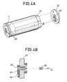
- a heater is arranged within the photosensitive drum 1 as the heating mechanism for heating the photoconductive layer 2. This heating mechanism will now be described in detail with reference to Figs. 2 and 3.
- Both the side faces of the drum 28 (1 in Fig. 1) are closed by flanges 21 and 21' having central openings 20 and 20', and a gear portion 22 is arranged on the circumferential end edge of one flange 21 to transmit the driving power from a driving motor to the drum 28.
- the rotation shaft 23 of the drum is not caused to participate directly in rotation and driving, but a heater 24 may be arranged as the heating mechanism at the position of the shaft 23 to heat the interior of the drum 28 and maintain the photosensitive layer 2 at a predetermined temperature.
- the flanges 21 and 21' are attached to both the side faces of the drum 1 by a plurality of rod members 25 having male screws on both the ends.
- the central portions of the flanges 21 and 21' have shapes including projections 26 and 26' outwardly projected and openings 20 and 20' formed at the centers thereof.
- a gear portion 22 is arranged on the circumferential end edge of one flange 21 to transmit the driving power of a driving motor (not shown) of the copying machine to the drum 28.
- the projections 26 and 26' are fitted in bearings 27 and 27' and the drum 28 is held on a drum rcceiver (not shown).
- the gear portion 22 is engaged with a driving gear of the copying machine, so that the photosensitive drum 28 is rotatably set at the copying machine.
- a heat source for example, a rod heater 24, is inserted from one of the openings 20 and 20' and is secured by heater electrode sockets 30 and 30' attached to the copying machine so that a voltage can be applied to the heater 24 from a power source 31.
- a hollow pope 32 or the like may be laid out between both the flanges 21 and 21' so as to facilitate the insertion of the heater 24.
- a Nichrome wire insulatingly covered on a thin stainless steel plate or a so-called film heater comprising a heating member sandwiched between two insulating films may be arranged within the photosensitive drum 28.
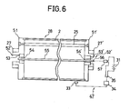
- the film filter 41 is inserted in the drum 1 and attached to the inner face of the drum 1.
- One electrode 42 is connected to the inner face of the drum 1 as the ground while the other electrode is connected to a connector 44 of a rotary brush electrode 43 arranged on the inner face side of the drum 1 on one flange 21' (composed of an insulating material such as Duracon).
- a heater voltage is applied from an external socket 46 through a fixed axial electrode 45, the voltage can be applied to the heater through the brush electrode 43 with rotation of the drum 1.
- control of the temperature of the photosensitive layer 2 heated by the heating mechanism is performed by a temperature-adjusting mechanism 47 described below.
- a temperature sensor 33 is attached in the vicinity of the surface of the photosensitive layer, and a control portion 34 for setting a predetermined temperature on receipt of a signal of the sensor 33 turns on or off a switch 35 of a heater circuit.
- a thermistor is arranged as temperature detecting means, and the output voltage to the heater is adjusted to 24 V.
- the heater is turned on or off by controlling the base current.of a transistor Tr connected in series to heater terminals CNB-1 and CNB-2.
- Control of the base current is performed by two comparators Cl and C2.
- One comparator Cl controls the base current of the transistor Tr based on the change of the electric resistance of the thermistor caused according to the change of the surface temperature of the drum.
- the other comparator C2 has a protecting function of controlling the base current of the transistor Tr so as to turn off the heater when breaking is caused in the thermistor.
- the comparator Cl compares the standard level on the negative side with the change of the voltage caused by the change of the resistance of the thermistor connected to the thermistor terminals CNB-3 and CNB-4 on the positive side, and based on the result of the comparison of both the levels, the comparator Cl is held at a low or high level.
- the comparator Cl is held at a high level, with the result that the base current of the transistor Tr flows and the heater is kept in the "on" state.
- the resistance of the thermistor is excessively lowered and the voltage on the positive side is lower than the standard level (on the negative side), with the result that the comparator is held at a low level. Accordingly, the base current of the transistor Tr does not flow and the heater is kept in the "off" state.
- a variable resistor is connected to the standard level (the negative side) so that the standard level can be changed to adjust the temperature.
- the comparator C2 acts as a protecting circuit, and a relatively high standard level is maintained on the positive side.
- the level of the positive side of the comparator Cl is higher than the standard level and the comparator Cl is held at a high level, but the level of the negative side of the comparator C2 is higher than the standard level on the positive side and hence, the comparator C2 is held at a low level. Since the base current of the transistor Tr does not flow if one of the comparators Cl and C2 is held at a low level, the base current of the transistor Tr does not flow in this case and the heater is turned off.
- bearings 53 and 53' are fitted in openings 52 and 52 t of flanges 51 and 51', and a heater 55 is attached to the central holes of the bearings through fixing members 54 and 54'.
- the heater 55 is attached to the copying machine before the photosensitive drum 28 is set at the copying machine.
- each of the numbers of the electrode and socket of the heater may be reduced to one (56 and 57 in the drawings), and connection to the power source 31 is facilitated.
- the heat source for heating the photoconductive layer 2 is disposed independently from the heat fixation mechanism, and even in the case where the photosensitive drum 28 is stopped, the photoconductive layer 2 can be uniformly heated. Therefore, even in the state where the operation of the copying machine is stopped, that is, in the case where the copying machine is not used in the night, the surface temperature of the photoconductive layer can be maintained at a level of 30 to 40°C, especially 35 to 40°C.
- the surface temperature of the photoconductive layer 2 be maintained at a level of 30 to 40°C.
- the apparatus is kept at room temperature in the night, if the drum is heated at the start of the operation of the apparatus, the flow of an image can be prevented. In this case, however, a certain time is necessary for stabilization for elevating the surface temperature of the photoconductive layer to the above-mentioned level.
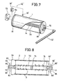
- a hollow shaft 70 is arranged to extend through the central portion of the drum 1, and hot air is supplied into this shaft 70 from the heat fixation mechanism 15 to heat the photoconductive layer 2 from the substrate side.
- one end of the hollow shaft 70 is connected to the heat fixation mechanism 15 through air feed pipes 71 and 71', and the other end of the hollow shaft 70 is connected to an exhaust fan 73 through an air supply pipe 72.
- Many small holes 74 are formed on this hollow shaft 70.
- a rubber plug 75 is arranged in the hollow portion of the shaft 70 to divide the hollow portion into two parts.
- flanges 81 and 81'- having central openings 80 and 80' are disposed on both the sides of the drum 1, and the openings 80 and 80' are formed to have shapes including projections 82 and 82' projected outwardly.
- the projections 82 and 82' are fitted in bearings 83 and 83' and the drum 1 is supported in a drum-receiving portion (not shown) of the copying machine.
- the driving power for the drum 1 is transmitted from a driving motor (not shown) through a gear 84 mounted on one flange 81 arranged on one side of the drum 1, whereby the drum 1 is rotated.
- the drum 1 has a closed structure except the openings 80 and 81'. Accordingly, outer air is prevented from flowing into the interior space of the drum 1, and heating of the photoconductive layer 2 by hot air is effectively performed. Moreover, supply of hot air from the heat fixation mechanism 15 can be accomplished very easily.
- Both the end portions of the hollow shaft 70 are connected to the inner sides of the flanges 81 and 81' so that the openings 80 and 80' of the flanges 81 and 81' are covered with both the end portions of the hollow shaft 70, and the air feed pipes 71 and 72 are directed to the interior space of the hollow shaft 70 through the openings 80 and 80'.
- the air feed pipes 71 and 72 are secured to the flanges 81 and 81' through the bearings 85 and 86. Accordingly, although the hollow shaft 70 is rotated together with the drum 1 when the drum 1 is driven and rotated, the air feed pipes 71 and 72 are kept stationary.
- the heat fixation mechanism 15 since the heat fixation mechanism 15 is used as the heat source, an independent heat source need not particularly be disposed, and hot air is not supplied to the photoconductive layer 2 from the outside but hot air is supplied to the interior of the drum to heat the photoconductive layer 2. Accordingly, heating can be performed very efficiently without any bad influence being given by air streams.
- this heating by hot air be continuously conducted, but heating may be performed intermittently, so far as the surface temperature of the photoconductive layer 2 is maintained at a level of 30 to 40°C, especially 35 to 40°C.
- Control of the surface temperature of the photoconductive layer 2 is performed by a temperature-adjusting mechanism 47'.
- This temperature-adjusting mechanism 47' is principally the same as the above-mentioned temperature-adjusting mechanism. Namely, the temperature-adjusting mechanism 47' comprises a temperature sensor 33' arranged on the surface of the photoconductive layer 2 and a controller 34'.
- the operation of the exhaust fan 73 is stopped instead of turn-off of the heater.
- the exhaust fan 73 is operated again.
- the surface temperature of the photoconductive layer is adjusted to the predetermined level.
- a hot air feed mechanism 91 comprises, for example, a fan 92 arranged to feed hot air to the surface of the photoconductive layer 2 through a passage 93. If the drum 1 is idly rotated when hot air is fed, hot air is fed to the surface of the photoconductive layer 2 by the fan 92 to effect heating of the photoconductive layer 2.
- the surface of the photoconductive layer 2 is locally exposed to a part of the passage 93 connected to a heat fixation zone A of the heat fixation mechanism 15, so that when hot air passes through this passage 93, the photoconductive layer 2 is heated.
- the position of the exposure of the photoconductive layer 2 to the passage 93 is not particularly critical but optional, so far as the position is not limited by the space in the copying machine. However, in view of the heating efficiency, it is preferred that the photoconductive layer 2 be exposed to the passage 93 in the vicinity of the,heat fixation mechanism 15.
- the wall of the passage 93 on the downstream side with respect to the rotation direction of the drum 1 be arranged to abut lightly to the surface of the photoconductive layer 2. Hot air from the heat fixation zone passes through the surface portion of the photoconductive layer 2 exposed within the passage 93 and is then discharged outside the copying machine by the fan 92.
- Control of the surface temperature of the photoconductive layer 2 is accomplished by means of a temperature control mechanism 47 similar to that adopted in the embodiment shown in Figs. 1 through 3. More specifically, when the surface temperature of the photoconductive layer 2 exceeds 40°C, the operation of the fan 92 is stopped by this control mechanism 47 to perform the temperature adjustment.
- the ceiling wall of the heat fixation mechanism 15 comprises a fixed wall 100 and a slidable wall 101, and the slidable wall 101 is set at a predetermined position by a spring'102.
- One end of the slidable wall 101 is connected to a solenoid 104 through a wire 103, and the wall 101 is slid by the operation of the solenoid 104 to form an opening 105.
- the slidable wall 101 is returned to the predetermined position by the spring 102 to shut the opening 105. Accordingly, a driving circuit is formed so that the solenoid 104 is operated synchronously with the fan 98. Accordingly, while hot air is not supplied, the heat fixation zone A is intercepted from the passage 93, and the heat loss is prevented.
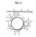
- heating of the photoconductive layer 2 can also be accomplished by using a hot roller.
- the structure of the copying machine comprising this heating mechanism is illustrated in Fig. 11.
- a hot roller 111 is arranged between a cleaning mechanism 12 and a main charging corona charger 3.
- the hot roller 111 is kept in contact with the photoconductive layer 2 to effect heating of the surface of the photoconductive layer 2.
- a silicone rubber roller having a heater 102 installed therein may be used as the hot roller 111, and a temperature control mechanism (not shown) similar to that adopted in the foregoing embodiments is disposed to perform the temperature control by turning on or off the heater 102 according to the surface temperature of the photoconductive layer 2.
- the hot roller 111 be kept in the state non-contacted with the photoconductive layer 2 while the copying operation is not performed and the drum 1 is stopped. Contact or non-contact of the hot roller 111 with the photoconductive layer 2 can easily be accomplished by using such means as a cam mechanism or solenoid mechanism (not shown).
- the heating mechanism as described hereinbefore is arranged so that the surface temperature of the photoconductive layer 2 be maintained at a level of 30 to 40°C.
- an interception mechanism be disposed to intercept the transfer corona charger 9 and the paper-separating corona charger 10 from the photoconductive layer 2 after termination of the copying operation.
- This problem of the flow of an image caused by the above-mentioned ions can be solved by intercepting the corona charger 10 from the photoconductive layer 2 after termination of the copying operation.
- Interception of the corona charger 10 from the photoconductive layer 2 can be accomplished by various methods.
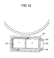
- An embodiment of this intercepting mechanism is illustrated in Fig. 12. Referring to Fig. 12, pulleys 122 are arranged around a charger unit 121 containing the charger 10 therein, and a wire 124 connected to an insulating film 123 is spread on the pulleys 122, so that the position of the insulating film 123 may be appropriately adjusted by rotating the pulleys 122. After termination of the copying operation, the pulleys 122 are rotated to cover the opening of the charger unit 121 by this intercepting film 123.
- This intercepting operation is carried out after the copying machine has been continuously used, and when the copying machine is used again, this interception is released.
- this interception may also be applied to the transfer corona charger 9.
- This transfer corona charger 9 effects charging of the same polarity as the charging polarity of the corona charger 3 for charging the photosensitive material, that is, positive charging.
- the quantities of the above-mentioned ions generated by this positive charging are small, since the transfer charger 9 is located below the photosensitive material, it is apprehended that these ions will be likely to stay in the transfer charger 9. Therefore, it is preferred that also the transfer charger 9 be intercepted from the photoconductive layer.
- the main charging corona charger 3 be intercepted from the photoconductive layer 2, though ions are hardly stored in the corona charger 3.
- an electrophotographic apparatus comprising a photosensitive layer of an amorphous silicon type photoconductor.
- the process comprising charging (positive charging), light exposure and removal of electricity (AC charging) was continuously repeated 30,000 times on a photosensitive drum of a-Si:H, whereby Si-0 bonds were formed on the surface of the drum.
- This drum was set in an ordinary copying machine, and the copying operation was continuously conducted 20 times, and then, the drum which was heated at several temperature was allowed to stand in an atmosphere maintained at a room temperature of 25°C and a relative humidity of 75 or 85°C for 10 hours at maximum.
- a film heater was uniformly bonded to the inner surface of the drum, and a heating mechanism comprising a brush electrode contacted with a sliding end terminal of the drum was arranged so that a voltage could be applied to the film heater even while the drum was rotated.
- the film heater used comprised an insulated and covered Nichrome wire arranged meanderingly at certain intervals on substantially all of one surface of a thin stainless steel substrate and a cotton cloth bonded to the surface of the Nichrome wire. After the above standing for 10 hours at maximum, the copying operation was continuously conducted at each ambient temperature of drum.
- the copying operation was continuously conducted 100 times in an atmosphere maintained at a room temperature of 25°C and a relative humidity of 75 % by using an a-Si:H drum where Si-0 bonds were formed as in Example 1 while changing the ambient temperature of the drum by using the heating mechanism shown in Figs. 2 and 3. If the ambient temperature of the drum was lower than 30°C, the flow of an image was caused when scores of prints were formed, but if the ambient temperature of the drum was at least 30°C, the flow of an image was not caused during the continuous copying operation.
- the ambient temperature of the drum exceeded 40°C, because of the inherent characteristic of the semiconductor, the dark resistivity was reduced and the image density was reduced in the prints. However, also in this case, the flow of an image was not caused.
- the relation between the ambient temperature of the drum and the image density retention ratio is shown in Fig. 13.
- the retention ratio in the drawings is a percent value calculated based on the assumption that the reflection density of the image area (solid black portion of 2 cm x 2 cm) measured by a reflection densitometer (Model TC-6D supplied by Tokyo Denshoku), which was 1.3, was 100 %.
Landscapes
- Physics & Mathematics (AREA)
- General Physics & Mathematics (AREA)
- Life Sciences & Earth Sciences (AREA)
- Engineering & Computer Science (AREA)
- Atmospheric Sciences (AREA)
- Biodiversity & Conservation Biology (AREA)
- Ecology (AREA)
- Environmental & Geological Engineering (AREA)
- Environmental Sciences (AREA)
- Control Or Security For Electrophotography (AREA)
- Discharging, Photosensitive Material Shape In Electrophotography (AREA)
Applications Claiming Priority (8)
| Application Number | Priority Date | Filing Date | Title |
|---|---|---|---|
| JP58180738A JPS6073633A (ja) | 1983-09-30 | 1983-09-30 | 電子写真方法の改良 |
| JP180738/83 | 1983-09-30 | ||
| JP202825/83 | 1983-10-31 | ||
| JP20282583A JPS6095551A (ja) | 1983-10-31 | 1983-10-31 | 電子写真方法 |
| JP17369283U JPS6082657U (ja) | 1983-11-11 | 1983-11-11 | 画像形成装置における感光体ドラムの加熱機構 |
| JP173692/83U | 1983-11-11 | ||
| JP18377083U JPS6092263U (ja) | 1983-11-30 | 1983-11-30 | 画像形成装置における感光体ドラムの加熱装置 |
| JP183770/83U | 1983-11-30 |
Publications (3)
| Publication Number | Publication Date |
|---|---|
| EP0136902A2 true EP0136902A2 (de) | 1985-04-10 |
| EP0136902A3 EP0136902A3 (en) | 1986-12-10 |
| EP0136902B1 EP0136902B1 (de) | 1990-01-31 |
Family
ID=27474521
Family Applications (1)
| Application Number | Title | Priority Date | Filing Date |
|---|---|---|---|
| EP84306674A Expired - Lifetime EP0136902B1 (de) | 1983-09-30 | 1984-09-28 | Elektrophotographische Einrichtung, eine lichtempfindliche Schicht von amorphem Silizium-Lichtleiter enthaltend |
Country Status (3)
| Country | Link |
|---|---|
| US (1) | US4607936A (de) |
| EP (1) | EP0136902B1 (de) |
| DE (1) | DE3481225D1 (de) |
Cited By (6)
| Publication number | Priority date | Publication date | Assignee | Title |
|---|---|---|---|---|
| DE3631495A1 (de) * | 1985-09-17 | 1987-03-26 | Canon Kk | Mit einer bilderzeugungsvorrichtung verwendbares bildtraegerelement |
| US4975744A (en) * | 1985-09-17 | 1990-12-04 | Canon Kabushiki Kaisha | Image bearing member and driving mechanism therefor |
| DE4040962A1 (de) * | 1989-12-20 | 1991-06-27 | Hitachi Ltd | Transfervorrichtung und elektrofotografisches geraet |
| EP0676678A1 (de) * | 1994-04-04 | 1995-10-11 | Mita Industrial Co. Ltd. | Bildaufzeichnungsgerät |
| EP0957404A1 (de) * | 1998-05-14 | 1999-11-17 | Canon Kabushiki Kaisha | Elektrophotographisches, lichtempfindliches Element und Bildherstellungsapparat |
| EP0957405A1 (de) * | 1998-05-14 | 1999-11-17 | Canon Kabushiki Kaisha | Bildherstellungsapparat |
Families Citing this family (28)
| Publication number | Priority date | Publication date | Assignee | Title |
|---|---|---|---|---|
| JPS61165764A (ja) * | 1985-01-17 | 1986-07-26 | Sharp Corp | 電子写真プロセス |
| US5019862A (en) * | 1986-01-23 | 1991-05-28 | Sharp Kabushiki Kaisha | Heat control for photoreceptor |
| JPS63125967A (ja) * | 1986-11-17 | 1988-05-30 | Canon Inc | 電子写真法用の像露光装置 |
| US5038166A (en) * | 1987-12-29 | 1991-08-06 | Canon Kabushiki Kaisha | Optical image recording apparatus |
| JPH0750356B2 (ja) * | 1988-09-30 | 1995-05-31 | キヤノン株式会社 | 電子写真装置 |
| US5177529A (en) * | 1988-11-25 | 1993-01-05 | Xerox Corporation | Machine with removable unit having two element electrical connection |
| JPH02251867A (ja) * | 1989-03-24 | 1990-10-09 | Hitachi Koki Co Ltd | 電子写真複写・印字装置 |
| GB2232244B (en) * | 1989-05-30 | 1992-11-18 | Deutsche Forsch Luft Raumfahrt | A device for measuring the temperature of a body in a vacuum |
| US5155531A (en) * | 1989-09-29 | 1992-10-13 | Ricoh Company, Ltd. | Apparatus for decomposing ozone by using a solvent mist |
| EP0466173B1 (de) * | 1990-07-13 | 1998-10-21 | Canon Kabushiki Kaisha | Arbeitseinheit und Bilderzeugungsgerät mit einer solchen Einheit |
| JP3169234B2 (ja) * | 1990-10-25 | 2001-05-21 | 株式会社リコー | 画像形成装置 |
| US5592274A (en) * | 1992-01-31 | 1997-01-07 | Fuji Xerox Co., Ltd. | Electrophotographic apparatus and process for simultaneously transferring and fixing toner image onto transfer paper |
| EP0679955B9 (de) * | 1994-04-27 | 2005-01-12 | Canon Kabushiki Kaisha | Elektrophotographisches lichtempfindliches Element und seine Herstellung |
| JP3368109B2 (ja) * | 1995-08-23 | 2003-01-20 | キヤノン株式会社 | 電子写真用光受容部材 |
| JP3862334B2 (ja) | 1995-12-26 | 2006-12-27 | キヤノン株式会社 | 電子写真用光受容部材 |
| KR19980026295U (ko) * | 1996-11-08 | 1998-08-05 | 김광호 | 레이져 빔 프린터용 히트 로울러의 온도 분포 균일화 구조 |
| US5788382A (en) * | 1997-08-28 | 1998-08-04 | Output Technology, Inc. | Imaging drum |
| JP3976955B2 (ja) | 1999-09-06 | 2007-09-19 | キヤノン株式会社 | 電子写真方法 |
| US6537714B2 (en) | 2000-07-07 | 2003-03-25 | Canon Kabushiki Kaisha | Image-forming method and image-forming apparatus |
| US6605405B2 (en) | 2000-07-26 | 2003-08-12 | Canon Kabushiki Kaisha | Electrophotographic method and electrophotographic apparatus |
| US6895209B2 (en) * | 2002-04-19 | 2005-05-17 | Ricoh Company, Ltd. | Cleaning device and image forming apparatus using the same |
| JP5000385B2 (ja) * | 2006-06-21 | 2012-08-15 | オセ−テクノロジーズ・ベー・ヴエー | プリンタ用のローラおよびローラの表面を冷却する方法 |
| EP1870781B1 (de) * | 2006-06-21 | 2013-08-14 | Océ-Technologies B.V. | Rolle für einen Drucker und Verfahren zur Kühlung der Rollenoberfläche |
| JP4850619B2 (ja) | 2006-08-14 | 2012-01-11 | キヤノン株式会社 | 画像形成装置 |
| JP5163086B2 (ja) * | 2007-12-12 | 2013-03-13 | 富士ゼロックス株式会社 | 画像形成装置 |
| JP5534873B2 (ja) * | 2010-03-09 | 2014-07-02 | キヤノン株式会社 | 画像形成装置 |
| JP5193247B2 (ja) * | 2010-03-31 | 2013-05-08 | 京セラドキュメントソリューションズ株式会社 | ホルダと感光体の冷却構造及びこれを備えた画像形成装置 |
| EP4097542A4 (de) * | 2020-03-26 | 2023-11-01 | Hewlett-Packard Development Company, L.P. | Heizung für eine drucktrommel |
Family Cites Families (7)
| Publication number | Priority date | Publication date | Assignee | Title |
|---|---|---|---|---|
| DE2265381C2 (de) * | 1971-06-03 | 1982-05-13 | Canon K.K., Tokyo | Verfahren zum Betreiben eines elektrophotographischen Kopiergeräts mit streifenförmiger Projektionsbelichtung einer Aufzeichnungstrommel |
| GB1497926A (en) * | 1975-03-04 | 1978-01-12 | Xerox Corp | Method for temperature stabilizing photoreceptors |
| US4161357A (en) * | 1977-09-02 | 1979-07-17 | Xerox Corporation | Photoreceptor heating apparatus |
| US4484809B1 (en) * | 1977-12-05 | 1995-04-18 | Plasma Physics Corp | Glow discharge method and apparatus and photoreceptor devices made therewith |
| US4344700A (en) * | 1978-12-08 | 1982-08-17 | Canon Kabushiki Kaisha | Mechanism for mounting and dismounting a screen-like photosensitive medium |
| US4299474A (en) * | 1979-12-26 | 1981-11-10 | International Business Machines Corporation | Component mounting apparatus useful for compact copiers |
| JPS59166980A (ja) * | 1982-11-29 | 1984-09-20 | Konishiroku Photo Ind Co Ltd | 静電画像記録装置 |
-
1984
- 1984-09-28 DE DE8484306674T patent/DE3481225D1/de not_active Expired - Lifetime
- 1984-09-28 EP EP84306674A patent/EP0136902B1/de not_active Expired - Lifetime
- 1984-09-28 US US06/655,533 patent/US4607936A/en not_active Expired - Fee Related
Cited By (8)
| Publication number | Priority date | Publication date | Assignee | Title |
|---|---|---|---|---|
| DE3631495A1 (de) * | 1985-09-17 | 1987-03-26 | Canon Kk | Mit einer bilderzeugungsvorrichtung verwendbares bildtraegerelement |
| US4839690A (en) * | 1985-09-17 | 1989-06-13 | Canon Kabushiki Kaisha | Image bearing member usable with image forming apparatus |
| US4975744A (en) * | 1985-09-17 | 1990-12-04 | Canon Kabushiki Kaisha | Image bearing member and driving mechanism therefor |
| DE4040962A1 (de) * | 1989-12-20 | 1991-06-27 | Hitachi Ltd | Transfervorrichtung und elektrofotografisches geraet |
| EP0676678A1 (de) * | 1994-04-04 | 1995-10-11 | Mita Industrial Co. Ltd. | Bildaufzeichnungsgerät |
| EP0957404A1 (de) * | 1998-05-14 | 1999-11-17 | Canon Kabushiki Kaisha | Elektrophotographisches, lichtempfindliches Element und Bildherstellungsapparat |
| EP0957405A1 (de) * | 1998-05-14 | 1999-11-17 | Canon Kabushiki Kaisha | Bildherstellungsapparat |
| US6122467A (en) * | 1998-05-14 | 2000-09-19 | Canon Kabushiki Kaisha | Image forming apparatus using an amorphous silicon photosensitive member having a thin cylinder |
Also Published As
| Publication number | Publication date |
|---|---|
| DE3481225D1 (de) | 1990-03-08 |
| EP0136902B1 (de) | 1990-01-31 |
| EP0136902A3 (en) | 1986-12-10 |
| US4607936A (en) | 1986-08-26 |
Similar Documents
| Publication | Publication Date | Title |
|---|---|---|
| US4607936A (en) | Electrophotographic apparatus comprising photosensitive layer of amorphous silicon type photoconductor | |
| JP2614865B2 (ja) | 同時転写定着装置を備えた電子写真式印字機 | |
| EP0338546B1 (de) | Aufladevorrichtung und Bilderzeugungsgerät mit dieser | |
| US8036565B2 (en) | Image forming apparatus including a mechanism to move a discharge wire cleaning member and a shutter for a corona charger | |
| JPS59166980A (ja) | 静電画像記録装置 | |
| US4109135A (en) | High efficiency fuser roll assembly for xerographic material | |
| JPS6095551A (ja) | 電子写真方法 | |
| JPH01142742A (ja) | 電子複写機 | |
| JPH0134205Y2 (de) | ||
| US5055879A (en) | Apparatus for ozoneless efficient charging of a photoreceptive drum in an electrophotographic printer | |
| JPH0450591B2 (de) | ||
| JPH0134206Y2 (de) | ||
| JP2587215B2 (ja) | 電子写真方法 | |
| JPH0121313Y2 (de) | ||
| JPS59208558A (ja) | 電子写真方法 | |
| JPH0455309B2 (de) | ||
| JP3095505B2 (ja) | 画像形成装置 | |
| JPH11218996A (ja) | 帯電装置 | |
| CA1097722A (en) | Electrophotographic copying apparatus | |
| JP3554645B2 (ja) | 画像形成装置 | |
| JPS59142581A (ja) | 電子写真式画像の安定化方法 | |
| KR940003876Y1 (ko) | 전자사진 방식을 이용한 프로세서의 정착장치 | |
| JPS6219754B2 (de) | ||
| JP3659458B2 (ja) | 電子写真感光体 | |
| JPH01284872A (ja) | 接触帯電装置 |
Legal Events
| Date | Code | Title | Description |
|---|---|---|---|
| PUAI | Public reference made under article 153(3) epc to a published international application that has entered the european phase |
Free format text: ORIGINAL CODE: 0009012 |
|
| AK | Designated contracting states |
Designated state(s): DE FR GB |
|
| PUAL | Search report despatched |
Free format text: ORIGINAL CODE: 0009013 |
|
| AK | Designated contracting states |
Kind code of ref document: A3 Designated state(s): DE FR GB |
|
| 17P | Request for examination filed |
Effective date: 19870113 |
|
| 17Q | First examination report despatched |
Effective date: 19880524 |
|
| GRAA | (expected) grant |
Free format text: ORIGINAL CODE: 0009210 |
|
| AK | Designated contracting states |
Kind code of ref document: B1 Designated state(s): DE FR GB |
|
| REF | Corresponds to: |
Ref document number: 3481225 Country of ref document: DE Date of ref document: 19900308 |
|
| ET | Fr: translation filed | ||
| PLBE | No opposition filed within time limit |
Free format text: ORIGINAL CODE: 0009261 |
|
| STAA | Information on the status of an ep patent application or granted ep patent |
Free format text: STATUS: NO OPPOSITION FILED WITHIN TIME LIMIT |
|
| 26N | No opposition filed | ||
| PGFP | Annual fee paid to national office [announced via postgrant information from national office to epo] |
Ref country code: FR Payment date: 19950911 Year of fee payment: 12 |
|
| PGFP | Annual fee paid to national office [announced via postgrant information from national office to epo] |
Ref country code: GB Payment date: 19950919 Year of fee payment: 12 |
|
| PGFP | Annual fee paid to national office [announced via postgrant information from national office to epo] |
Ref country code: DE Payment date: 19950928 Year of fee payment: 12 |
|
| PG25 | Lapsed in a contracting state [announced via postgrant information from national office to epo] |
Ref country code: GB Effective date: 19960928 |
|
| PG25 | Lapsed in a contracting state [announced via postgrant information from national office to epo] |
Ref country code: FR Effective date: 19960930 |
|
| GBPC | Gb: european patent ceased through non-payment of renewal fee |
Effective date: 19960928 |
|
| PG25 | Lapsed in a contracting state [announced via postgrant information from national office to epo] |
Ref country code: DE Effective date: 19970603 |
|
| REG | Reference to a national code |
Ref country code: FR Ref legal event code: ST |
|
| REG | Reference to a national code |
Ref country code: FR Ref legal event code: ST |