EP0134809B1 - Verfahren und vorrichtung zur darstellung einer kurve gleichmässiger breite - Google Patents
Verfahren und vorrichtung zur darstellung einer kurve gleichmässiger breite Download PDFInfo
- Publication number
- EP0134809B1 EP0134809B1 EP84900788A EP84900788A EP0134809B1 EP 0134809 B1 EP0134809 B1 EP 0134809B1 EP 84900788 A EP84900788 A EP 84900788A EP 84900788 A EP84900788 A EP 84900788A EP 0134809 B1 EP0134809 B1 EP 0134809B1
- Authority
- EP
- European Patent Office
- Prior art keywords
- data
- points
- curve
- rectangles
- curves
- Prior art date
- Legal status (The legal status is an assumption and is not a legal conclusion. Google has not performed a legal analysis and makes no representation as to the accuracy of the status listed.)
- Expired - Lifetime
Links
Images

Classifications
-
- G06T11/23—
-
- G—PHYSICS
- G06—COMPUTING OR CALCULATING; COUNTING
- G06T—IMAGE DATA PROCESSING OR GENERATION, IN GENERAL
- G06T11/00—2D [Two Dimensional] image generation
- G06T11/20—Drawing from basic elements, e.g. lines or circles
- G06T11/203—Drawing of straight lines or curves
Definitions
- the present invention relates generally to the field of computer aided graphic arts. More specifically the invention relates to a method and apparatus for representation of and recreation of lines or curves having a predetermined, uniform width.
- Computer aided or generated graphics systems are used in a wide range of applications, including information display, creation of images for photographic and printing applications, and computer aided design and manufacturing of a wide variety of products and components. Creation of two dimensional figures via a display media is currently accomplished in the computer aided graphic arts by storing large amounts of digitized figure coordinate data. Current systems of this type are subject to certain problems in terms of the size of memory required to store a particular figure, computation time for reconstructing the figure from the stored data, and flexibility of application in terms of ability to handle arbitrary shapes, as opposed to a limited number of predetermined shapes, and flexibility in editing and manipulating these shapes.
- the present invention solves these and many other problems present in the computer aided graphic arts.
- the present invention relates to a method and apparatus of providing a grahical representation of a curve with a uniform width.
- the present invention utilizes a set of data points generally lying along the curve by converting the data points into second order parametric equations which define a plurality of adjoining curve segments closely approximating the curve.
- the present invention relates to method and apparatus, as set out in claims 1 and 10, respectively for converting the curve segments into straight line segments and defining in association with each of the straight line segments the coordinates of a rectangle having a width equal to the width of the curve.
- a particularly advantageous feature of the present invention is the provision of the ability to readily scale, rotate, reshape, etc. graphic presentations while present on a medium without disturbing the uniform width thereof.
- a curve series is defined as a plurality of interconnected curves wherein the curves are defined by second order parametric Bezier curves and straight line segments.
- the present invention provides a computer based system for providing a curve series of substantially uniform, predetermined width.
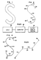
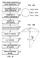
- FIGURE 1 Illustrated in FIGURE 1 is an arbitrary form which in this instance approximates the letter "s".
- FIGURE 2 Shown in FIGURE 2 is a curve series representation of the letter "s". Note that the curve series is defined by a series of vertices or node points 22 interconnected by a series of curves 24. In this particular example there are six curves, 24 and seven node points 22.
- the present invention enables the curve series of FIGURE 2 to be provided with a uniform width therealong so as to closely approximate the letter "s" as shown in FIGURE 1.
- two dimensional figure data is normally obtained from an input device 26 such as a digitizing tablet.
- the figure data in turn is processed by a computer 28 in accordance with the present invention which in one embodiment of the present invention is a PDP 11/34 or PDP 11/23.
- the resulting data is then output to a display medium 30 for visual presentation of the figure for which the data was received and processed. Examples of the types of display media which might be utilized are raster scan frame buffer displays, film recorders, plotters, etc.
- figure data is obtained from a digitizing tablet.
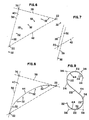
- the raw figure data represents coordinate positions 32 representative of the figure as illustrated in FIGURE 4 where the figure "s" data is illustrated.
- the slope between two adjacent points is calculated. Those coordinates which are determined to be X maxima or minima, Y maxima or minima, inflection points, and start and end points are saved and designated as node points 22. Note that in order to determine when there is an inflection point, the slope data (S1, S2, S3) for three consecutive pairs of points 32 is saved. If either of the following conditions are met then there is an inflection point:
- FIGURE 6 a group of data points 32 two of which are node points 22 is shown. At any given time during the processing of figure data, data points 32 lying on a span between adjacent nodes 22 are saved as is one data point 32 on either side of this span. When two adjacent nodes 22 are detected, a slope control point 36 is determined by the intersection of two control lines or frames 38. Control point 36 thus lies at the vertex of a triangle 40 defined by control lines 38 connecting nodes 22 to control point 36 and a base line 42 interconnecting nodes 22.
- each control line 38 has the same slope as and is parallel to the line 39 interconnecting data points 32 on either side of node 22 through which line 38 extends.
- the two nodes 22 and control point 36 may then be used to define a Bezier curve 44 as illustrated in FIGURE 8 which approximates that of the figure boundary between adjacent nodes 22 as defined by data points 32.
- Control point 36 and nodes 22 are then stored in memory and the data points 32 are discarded except for the data point 32 immediately preceding the last node 22 detected.
- Subsequent data coordinate positions 32 are then saved until a subsequent node 22 is detected at which point the processing on this set of data is performed. This processing continues for each pair of nodes 22 detected until the entire boundary of the curve series has been defined and/or terminated by the operator.
- Each Bezier curve 44 is tangent to the control frames 38 at nodes 22.
- node points 22 and control points 36 which are stored in memory define the curve series, in this case representative of the letter "s". Note that the dots illustrate the outline of the resulting Bezier curves 44.
- curve fitting processing is performed in real time as the figure data is received from the input device.
- selective figure data is obtained and saved in memory for later processing as desired.
- the final data set which is saved in memory for representation of a given curve series includes all the detected nodes 22 and their associated control points 36. This requires much less memory than the storage of all figure data points 32 and minimizes delays due to the processing of such a large data set. Furthermore, the data set requiring transformation processing for display purposes is reduced and easier to operate on. In addition, a smooth figure boundary can be presented at any resolution at the display media.
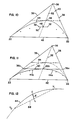
- the resulting Bezier curve 44 is compared with the corresponding figure data 32. If the deviation is greater than a specified threshold value, a node 22 will be added and the Bezier curve will be divided into two Bezier curves. The resulting Bezier curves are similarly tested in a recursive fashion until the threshold value is achieved.
- the properties of the Bezier polygon are used to estimate the maximum deviation from the actual data.
- a flexer point 46 of maximum displacement of Bezier curve 44 from base 42 of triangle 40 may be quickly computed from the triangle geometry.
- the point 48 of maximum figure data displacement from base 42 of triangle 40 is easily computed by checking for the intersection of a line 50 with a line 52 which extends from control point 36 to a point at the midsection of base 42 of triangle 40.
- Line 50 is defined by the two data points 32 closest to line 52 and on either side thereof. The distance between points 46 and 48 is then computed and compared with the predetermined threshold to see if a subdivision is necessary.
- a node 22a is inserted at point 46 and then control points 36a, b on either side are defined at the intersection point of line 50 with sides 38 of triangle 40 as illustrated in FIGURE 11.
- the Bezier curve math may then be performed in each of the two new Bezier curves 44a, b and compared with the predetermined threshold. Further Bezier curve splitting may be carried out in a recursive fashion until the threshold is met and the desired accuracy of fit is derived between Bezier curves 44 and data points 32.
- the polygon data includes the coordinates of the polygon vertices.
- the coordinates of the polygon vertices are derived by substituting evenly incremented values of Z between zero and one into the Bezier curve parametric equations of each Bezier curve defining the edges of the curve series represented.
- the resultant polygon must have a sufficient number of vertices such that the polygon edges will appear smooth on the display device.
- the number of vertices needed per Bezier curve 44 between adjacent nodes 22 for a smooth appearance should be maintained at a minimum to reduce the computational time for generating the vertex list, clipping the resultant polygon, and scanline conversion of the polygon.
- the minimum number of vertices required to assure a smooth appearance will depend on the resolution of the viewing device, the length of the span between nodes, the radius of curvature at each point along the span, etc.
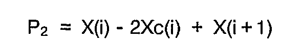
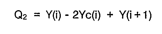
- the number of vertices or straight line segments required for a given Bezier curve is determined by measuring the distance E between a point C lying on the Bezier curve 44 between two adjacent vertices V0, V1 and a point L lying on a polygon line segment 86 between vertices V0, V1.
- the X, Y coordinates for C and L, (Cx, Cy) and (Lx, Ly) are defined by the parametric equations defining the Bezier curve wherein the points C and L represent an incremental value of Z which is only one half that between vertices V0, V1:
- the difference in X coordinates is:
- the difference in Y coordinates is :
- Distance E between points C and L may thus be represented as:
- the above equation may be rewritten as follows:
- distance E the number of straight line segments required for a given Bezier curve may be determined as discussed above.
- a distance E is one half of a raster step.
- distance E 1/2, the number of straight line segments or steps is:
- the number of line segments will be: CEILING [SQRT[SQRT ((XSN P2/XSD)2 +(YSN Q2/YSD)2) /2]] where CEILING will round a real number upward. If only integers are used, then the number of line segments will be: SQRT [SQRT ((XSN P2/XSD)2+ (YSN Q2/YSD)2) /2]+1
- the increment in the parameter is easily calculated as 1/NSTEP and the vertices of the line segments calculated by inserting incremental values of Z into the parametric equation for the Bezier curve.
- Newton Raphson's method may then be used to derive the number of straight line or steps.
- the above discussed magnitude computation method has a maximum error of approximately 3%.
- the computation is invariant with respect to rotation.
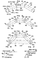
- the present invention provides for the line segments 86 to be expanded such that the individual curves of the curve series are provided with a predetermined width.
- a predetermined width (W) selected by an operator or automatically predetermined the present invention provides for the definition of a rectangle 100 having the width (W) along each of the line segments 86 of the Bezier curves 44.
- the line segments 86 divide their associated rectangles 100 into two equal portions each having a width of 1/2 W and intersect the ends 102 of the rectangles 100 at a 90° angle so as to be perpendicular thereto.
- the determination of the four corner coordinates of each of the rectangles 100 is as follows: Given: Given:
- each of the rectangles 100 are smoothed and rounded such that the adjacent rectangles 100 aligned end for end form a curve of predetermined width (W).
- W predetermined width
- the polygons representative of the circles 104 can then be displayed utilizing a scan conversion algorithm.
- the polygon determination is made as follows: Given :
- n [ 2 ⁇ ⁇ ]
- n [ 2 ⁇ ⁇ ]
- n must be an integer, so round result upward.
- e R[1-cos( ⁇ 2 )]
- e 1 ⁇ 2 (1 ⁇ 2 is pixel error on the output device resolution).
- the XP(i), YP(i) are computed as follows :
- i 1, ...., n
- a curve series may be converted into a curve of predetermined width providing a graphic representation of a two dimensional form; for example, the curve series of FIGURE 2 may be accordingly made to appear as the character "s" of FIGURE 1.
- the operator may also request the curve series be closed and not opened as in FIGURE 13.
- the present invention will connect the first and last vertices V0, V3 Of FIGURE 15 with a straight line 86 and its associated rectangle and round the corners if so requested by the operator.
- the operator may select the following parameters:
- the first four parameters have previously been discussed.
- the fifth parameter indicates whether the Bezier curves are to be determined or the individual data connected by straight lines. If point input mode is selected, then the operator manually marks each location at the input device which is to be utilized in determining the Bezier curves of the figure. In the stream input mode, figure data is periodically input to the processing unit.
- SX and SY are the scaling factors of the X and Y coordinates.
- the curve series may also be rotated about a reference point XR, YR, through an angle A by preforming a rotation on all vertices and control points as follows:
- X new XR + (X - Xr) Cos A + (Y - Yr) Sin A
- Y new YR - (X - Xr) Sin A + (Y - Yr) Cos A
- the preferred embodiment to the present invention further enables an operator to select a curve series on a display.
- the operator indicates a coordinate position on the screen by, for example, the use of cursor.
- the curve series data for each curve series of the display is converted into rectangle and partial circle data reflecting a curve series of predetermined width. A check is then made to ascertain in which a rectangle or partial circle in a coordinate position was contained. The operator than able to perform whenever operation are necessary on the selected curve series are selected.
- the preferred embodiment of the present invention enables an operator to modify a curve series figure by either modifying the flexer points 46 or the vertices 22.
- modification of the flexer points 46 and the vertices 22 has varying results on the curve series. This is accomplished by the operator moving a cursor along the vertices 22 and flexers 46 of a curve series. When the cursor is positioned over the appropriate flexer or vertex, the operator then moves the cursor to the desired new location and enters the coordinate position of the cursor. The flexer or vertex selected is then moved to the designated location resulting in a modification of the curve series as illustrated in the example of FIGURE 16 and 17.
- Illustrated in FIGURE 18 is an example of the processing sequence from curve series vertices 22 and control points 36 determination through imaging of a figure on a graphic device.
- the curve series description data must first be determined as previously discussed.
- transformations are performed such as scaling, translation, perspectives, rotation, etc. using well known transformation routines. It is important to note that significant reduction in processing is achieved by performing the transformations with curve series data which is a minimum data set before conversion of the data set to a polygon data set which is an expanded data set.
- step 64 a transformation to screen coordinates is performed. This may be accomplished by any one of several well known conversion techniques.
- step 65 the Bezier curves 44 are converted to line segments and in step 66, the associated rectangles and pies or circles are calculated.
- step 67 the data is converted and expanded to polygon data as described above. Once the polygon data has been established, at step 68 well known clipping algorithms can be used to clip portions of the polygon data which will not be displayed on the viewing device. Finally, at step 70, a scanline conversion of the polygon data is performed. At step 72 the figure representation is next displayed on the graphic device.
- a feature which allows insertion, deletion, and modification of Bezier curves 44 whereby the overall shape of a curve series can be edited.
- This feature provides for the smoothing of the junction between two adjacent Bezier curves 44.
- four types of junctions are curve-curve, curve-line, line-curve, and line-line.
- two new Bezier curves 44a are defined by moving control points 36 in along control frame 38 to define new control points 36a.
- New control points 36a are at the intersection of a line 82a which passes through node 22a and control frame 38 and is parallel to line 82 between control points 36.
- New curves 44a are thus the resulting Bezier curves defined by each set of nodes 22 and 22a and their associated control point 36a.
- a new curve 44a is defined by moving control point 36 in along control frame 38 to define a new control point 36a at the intersection of line 80 and control frame 38.
- FIGURE 21 where there is a line 80 and Bezier curve 44 junction.
- node 22a which is the junction of two lines 80 is used as the new control point for a new curve 44a.
- the above described feature thus enables modification of a curve series so as to more accurately represent the form desired.
- the present invention provides a method and apparatus for graphic representation of a curve or two dimensional figure having a predetermined, uniform width. Furthermore, the present invention provides for scaling, rotation, reshaping, etc. of the two dimensional form while maintaining the uniform width. Additionally, the present invention provides for the graphic representation of a two dimensional form of uniform width and having a relatively smooth boundary.
Landscapes
- Physics & Mathematics (AREA)
- General Physics & Mathematics (AREA)
- Engineering & Computer Science (AREA)
- Theoretical Computer Science (AREA)
- Image Generation (AREA)
- Processing Or Creating Images (AREA)
- Complex Calculations (AREA)
- Digital Computer Display Output (AREA)
- Fittings On The Vehicle Exterior For Carrying Loads, And Devices For Holding Or Mounting Articles (AREA)
- Eye Examination Apparatus (AREA)
Claims (10)
- Verfahren zur grafischen Darstellung einer zweidimensionalen Form gleichmäßiger Breite auf einem Anzeigemedium in einem computerunterstützten oder -erzeugten Grafiksystem, mit den Schritten
Bereitstellen eines Satzes von Datenpunkten, die im allgemeinen entlang einer longitudinalen Mittellinie der zweidimensionalen Form liegen;
Umwandeln der Datenpunkte in zweite Sätze von Daten für parametrische Gleichungen zweiter oder höherer Ordnung, welche eine Vielzahl von benachbarten Kurven definieren, die sich eng der Mittellinie annähern; und
Umwandeln des zweiten Satzes von Daten in eine Vielzahl von Liniensegmenten, die sich jeder der benachbarten Kurven eng annähern,
gekennzeichnet durch
Definieren von vier Koordinaten eines Rechteckes mit einer vorbestimmten gleichförmigen Breite für jedes Liniensegment, wobei jedes der Rechtecke durch sein zugeordnetes Liniensegment in zwei im wesentlichen gleiche Bereiche geteilt wird, wobei die Rechtecke im allgemeinen die zweidimensionale Form definieren;
Glätten der Verbindung der Rechtecke; und
Wiedererzeugen einer grafischen Darstellung der zweidimensionalen Form aus den glatten Rechteckdaten. - Verfahren nach Anspruch 1, dadurch gekennzeichnet, daß das Umwandeln der zweiten Sätze von Daten das Umwandeln der zweiten Sätze von Daten in Sätze von Daten für eine Vielzahl von benachbarten geraden Liniensegmenten umfaßt, die sich den durch die zweiten Sätze von Daten definierten Kurven eng annähern.
- Verfahren nach Anspruch 2, dadurch gekennzeichnet, daß das Umwandeln der zweiten Sätze von Daten in Daten für eine Vielzahl von geraden Liniensegmenten das Addieren einer ersten Inkrementgröße zu den vorliegenden Koordinaten und das Addieren einer zweiten Inkrementgröße zu der ersten Inkrementgröße umfaßt.
- Verfahren nach Anspruch 1, dadurch gekennzeichnet, daß das Umwandeln der Datenpunkte in zweite Sätze von Daten für parametrische Gleichungen zweiter oder höherer Ordnung, welche eine Vielzahl von benachbarten Kurven definieren, die der Mittellinie eng angenähert sind, das Analysieren des Satzes von Datenpunkten umfaßt, die den Außenumfang der Form darstellen, um als Knotenpunkte den Maximalwert, den Minimalwert, Start-, End- und Wendepunkte der Form zu identifizieren, und das Einrichten von Kontrollpunkten für benachbarte Paare von Knotenpunkten umfaßt, wobei die Kontrollpunkte und die Knotenpunkte parametrische Kurven zweiter oder höherer Ordnung definieren, die die Knotenpunkte so miteinander verbinden, daß sie sich eng der Mittellinie annähern.
- Verfahren nach Anspruch 4, dadurch gekennzeichnet, daß das Einrichten von Kontrollpunkten für benachbarte Paare von Knotenpunkten das Definieren einer Kontrollinie durch jeden der Knotenpunkte benachbarter Paare von Knotenpunkten umfaßt, wobei die Kontrollinien parallel zu einer Linie durch die Datenpunkte auf jeder Seite der Knotenpunkte, durch welche sich die Kontrollinie erstreckt, parallel sind, wobei die Kontrollpunkte durch den Schnitt der Kontrollinien der benachbarten Paare von Knotenpunkten definiert sind.
- Verfahren nach Anspruch 5, dadurch gekennzeichnet, daß die Vielzahl benachbarter Kurven Bezier-Kurven aufweisen.
- Verfahren nach Anspruch 6, dadurch gekennzeichnet, daß die Bezier-Kurven durch die folgenden parametrischen Gleichungen definiert sind:


wobei Z sich zwischen 0 und 1 ändert und wobei P₀, P₁, P₂, Q₀, Q₁ und Q₂ wie folgt definiert sind:


Xc(i), Yc(i) sind Kontrollpunktkoordinaten zwischen benachbarten Knoten, deren Koordinaten X(i), Y(i) und X(i+1), Y(i+1) sind. - Verfahren nach Anspruch 1, dadurch gekennzeichnet daß das Umwandeln des zweiten Satzes von Daten in eine Vielzahl von Liniensegmenten das Messen eines Abstandes E zwischen einem Punkt C, der auf einer der Kurven zwischen zwei benachbarten Scheitelpunkten liegt, und einem Punkt L, der auf einem Polygon-Liniensegment zwischen den Scheitelpunkten liegt, und das Auswählen eines Maximalwertes für den Abstand E umfaßt, so daß die Anzahl der geraden Liniensegmente, die für eine gegebene parametrische Kurve erforderlich sind, durch die folgende Gleichung bestimmt werden kann:

- Verfahren nach Anspruch 1, dadurch gekennzeichnet, daß das Glätten der Verbindung der Rechtecke das Definieren eines Kreises mit einem Mittelpunkt am Schnitt jeder der Liniensegmente und weiterhin mit einem Durchmesser, der gleich der Breite der Rechtecke ist, die den Liniensegmenten zugeordnet sind, umfaßt, so daß ein Bogen des Kreises, der voneinander beabstandete Ecken des Rechteckes verbindet, verwendet wird, um die Verbindung der Rechtecke zu glätten.
- Vorrichtung zur grafischen Darstellung einer zweidimensionalen Form auf einem Anzeigemedium in einem computerunterstützten oder -erzeugten Grafiksystem, mit einer Eingabevorrichtung zum Eingeben eines Satzes von Datenpunkten, die im allgemeinen entlang einer Linie angeordnet sind, welche eine longitudinale Konfiguration hat, die der zweidimensionalen Form ähnlich ist; einer ersten Überwachungseinrichtung zum Umwandeln der Datenpunkte in zwei Sätze von Daten für parametrische Gleichungen zweiter oder höherer Ordnung, welche eine Vielzahl von benachbarten Kurvensegmenten definieren, die sich der Linie eng annähern;
einer zweiten Überwachungseinrichtung zum Umwandeln jedes der Kurvensegmente in eine oder mehrere gerade Liniensegmente, gekennzeichnet durch eine dritte Überwachungseinrichtung, welche für jede der Liniensegmente Eckkoordinaten definiert, die einem Rechteck zugeordnet sind, wobei sich die Rechtecke der Konfiguration der zweidimensionalen Form eng annähern; einer vierten Überwachungseinrichtung zum Glätten der Enden der Rechtecke; und
einer Einrichtung zum Darstellen der glatten Rechteckdaten auf einem Medium, um so die zweidimensionale Form eng anzunähern.
Priority Applications (1)
| Application Number | Priority Date | Filing Date | Title |
|---|---|---|---|
| AT84900788T ATE70137T1 (de) | 1983-01-20 | 1984-01-18 | Verfahren und vorrichtung zur darstellung einer kurve gleichmaessiger breite. |
Applications Claiming Priority (2)
| Application Number | Priority Date | Filing Date | Title |
|---|---|---|---|
| US459394 | 1983-01-20 | ||
| US06/459,394 US4620287A (en) | 1983-01-20 | 1983-01-20 | Method and apparatus for representation of a curve of uniform width |
Publications (3)
| Publication Number | Publication Date |
|---|---|
| EP0134809A1 EP0134809A1 (de) | 1985-03-27 |
| EP0134809A4 EP0134809A4 (de) | 1987-09-22 |
| EP0134809B1 true EP0134809B1 (de) | 1991-12-04 |
Family
ID=23824594
Family Applications (1)
| Application Number | Title | Priority Date | Filing Date |
|---|---|---|---|
| EP84900788A Expired - Lifetime EP0134809B1 (de) | 1983-01-20 | 1984-01-18 | Verfahren und vorrichtung zur darstellung einer kurve gleichmässiger breite |
Country Status (12)
| Country | Link |
|---|---|
| US (1) | US4620287A (de) |
| EP (1) | EP0134809B1 (de) |
| JP (1) | JPS60500385A (de) |
| CA (1) | CA1207913A (de) |
| DE (1) | DE3485316D1 (de) |
| DK (1) | DK443284A (de) |
| ES (1) | ES8702680A1 (de) |
| FI (1) | FI843697L (de) |
| IL (1) | IL70735A0 (de) |
| NO (1) | NO843738L (de) |
| WO (1) | WO1984002993A1 (de) |
| ZA (1) | ZA84444B (de) |
Families Citing this family (70)
| Publication number | Priority date | Publication date | Assignee | Title |
|---|---|---|---|---|
| JPS6074003A (ja) * | 1983-09-30 | 1985-04-26 | Ryozo Setoguchi | 形状創成装置 |
| US4805127A (en) * | 1985-03-12 | 1989-02-14 | Mitsubishi Denki Kabushiki Kaisha | Image describing apparatus |
| CA1274919C (en) * | 1985-07-27 | 1990-10-02 | METHOD AND DEVICE FOR FORMING CURVE SURFACES | |
| NL8503461A (nl) * | 1985-12-17 | 1986-04-01 | Oce Nederland Bv | Werkwijze voor het genereren van lijnstukken. |
| US4875033A (en) * | 1986-06-05 | 1989-10-17 | Mitsubishi Denki Kabushiki Kaisha | Graphics input apparatus |
| US4797836A (en) * | 1986-11-19 | 1989-01-10 | The Grass Valley Group, Inc. | Image orientation and animation using quaternions |
| US5644654A (en) * | 1987-04-06 | 1997-07-01 | Canon Kabushiki Kaisha | Image processing apparatus capable of efficient coding of complex shape information |
| GB2204767B (en) * | 1987-05-08 | 1991-11-13 | Sun Microsystems Inc | Method and apparatus for adaptive forward differencing in the rendering of curves and surfaces |
| EP0342752B1 (de) * | 1988-05-20 | 1997-08-06 | Koninklijke Philips Electronics N.V. | Rechnerverfahren und Gerät zur Erzeugung eines Anzeigebildes, das einen Objektelementensatz mit einem Pinselobjektelement darstellt |
| JP2790815B2 (ja) * | 1988-08-10 | 1998-08-27 | 株式会社リコー | 画像データ圧縮方法 |
| US5261032A (en) * | 1988-10-03 | 1993-11-09 | Robert Rocchetti | Method for manipulation rectilinearly defined segmnts to form image shapes |
| AU624137B2 (en) * | 1988-10-03 | 1992-06-04 | Sun Microsystems, Inc. | Method and apparatus for image manipulation |
| AU629210B2 (en) * | 1988-10-26 | 1992-10-01 | Sun Microsystems, Inc. | Method and apparatus for minimizing the visual degradation of digital typefaces |
| JP2833654B2 (ja) * | 1988-11-11 | 1998-12-09 | キヤノン株式会社 | 図形処理装置 |
| US5241654A (en) * | 1988-12-28 | 1993-08-31 | Kabushiki Kaisha Toshiba | Apparatus for generating an arbitrary parameter curve represented as an n-th order Bezier curve |
| US5179647A (en) * | 1989-01-09 | 1993-01-12 | Sun Microsystem, Inc. | Method and apparatus for implementing adaptive forward differencing using integer arithmetic |
| EP0378754A3 (de) * | 1989-01-19 | 1992-03-18 | Hewlett-Packard Company | Polygonglättungsverfahren |
| US5086482A (en) * | 1989-01-25 | 1992-02-04 | Ezel, Inc. | Image processing method |
| US5208904A (en) * | 1989-03-07 | 1993-05-04 | Brother Kogyo Kabushiki Kaisha | Data processing apparatus and method for preparing data representative of supplemental figure attached to basic figure reproduced on output medium |
| JP2621463B2 (ja) * | 1989-03-07 | 1997-06-18 | ブラザー工業株式会社 | 図形処理装置 |
| US4991115A (en) * | 1989-05-16 | 1991-02-05 | Excellon Industries, Inc. | Method of mapping geometric entities from a continuous plane to a discrete plane |
| JPH0378795A (ja) * | 1989-08-22 | 1991-04-03 | Toshiba Corp | 文書作成装置 |
| JPH03121575A (ja) * | 1989-10-04 | 1991-05-23 | Stanley Electric Co Ltd | 曲線近似方法および曲線の記憶方法 |
| US5471573A (en) * | 1989-12-07 | 1995-11-28 | Apple Computer, Inc. | Optimized scan conversion of outlines for generating raster images |
| JPH03259296A (ja) * | 1990-03-09 | 1991-11-19 | Canon Inc | パターン発生装置 |
| GB2244892B (en) * | 1990-06-08 | 1994-12-14 | Electronic Graphics Ltd | Computer graphics |
| GB2248754A (en) * | 1990-06-13 | 1992-04-15 | Rank Cintel Ltd | Electronic painting system |
| JPH0810467B2 (ja) * | 1990-06-14 | 1996-01-31 | ゼロックス コーポレイション | ストロークに相当する輪郭線を迅速に生成する曲線近似方法 |
| JPH0458378A (ja) * | 1990-06-28 | 1992-02-25 | Mitsubishi Heavy Ind Ltd | ベジエ曲線を分割して展開する方法 |
| JP3189276B2 (ja) * | 1990-09-12 | 2001-07-16 | ブラザー工業株式会社 | データ変換装置 |
| JP2522108B2 (ja) * | 1990-10-17 | 1996-08-07 | 株式会社精工舎 | 曲線近似方法 |
| JP2522107B2 (ja) * | 1990-10-17 | 1996-08-07 | 株式会社精工舎 | 曲線近似方法 |
| GB2256118A (en) * | 1991-05-21 | 1992-11-25 | Cambridge Animation Syst | Image synthesis and processing |
| US5692117A (en) * | 1990-11-30 | 1997-11-25 | Cambridge Animation Systems Limited | Method and apparatus for producing animated drawings and in-between drawings |
| GB2253772B (en) * | 1991-03-12 | 1995-01-25 | Honda Motor Co Ltd | Method of creating solid model |
| JPH06507742A (ja) * | 1991-05-21 | 1994-09-01 | ケンブリッジ アニメーション システムズ リミテッド | 動画作成装置 |
| JPH0512442A (ja) * | 1991-07-02 | 1993-01-22 | Hitachi Software Eng Co Ltd | 線画像追跡方法 |
| US5325477A (en) * | 1991-12-02 | 1994-06-28 | Xerox Corporation | Method and apparatus for generating and displaying freeform strokes |
| US5592599A (en) * | 1991-12-18 | 1997-01-07 | Ampex Corporation | Video special effects system with graphical operator interface |
| US5280576A (en) * | 1991-12-24 | 1994-01-18 | Xerox Corporation | Method of adjusting the weight of a character of an outline font |
| US5341467A (en) * | 1991-12-30 | 1994-08-23 | Xerox Corporation | Method and apparatus for generating and displaying freeform strokes of varying or constant width using adaptive forward differencing |
| US5353396A (en) * | 1992-06-04 | 1994-10-04 | Altsys Corporation | System and method for generating complex calligraphic curves |
| US5367617A (en) * | 1992-07-02 | 1994-11-22 | Microsoft Corporation | System and method of hybrid forward differencing to render Bezier splines |
| US5363479A (en) * | 1992-07-02 | 1994-11-08 | Microsoft Corporation | System and method for rendering bezier splines |
| US5333248A (en) * | 1992-07-15 | 1994-07-26 | International Business Machines Corporation | Method and system for the smooth contouring of triangulated surfaces |
| EP0604685A1 (de) * | 1992-12-28 | 1994-07-06 | Océ-Nederland B.V. | Methode zur Modifizierung des Fettdruckens von Buchstaben |
| US5542030A (en) * | 1993-06-14 | 1996-07-30 | Electronic Data Systems Corporation | System and method for optimizing surface projections during generation of finite element representations of objects |
| JP2571662B2 (ja) * | 1993-09-01 | 1997-01-16 | インターナショナル・ビジネス・マシーンズ・コーポレイション | 線描画方法及び装置 |
| JPH07182537A (ja) * | 1993-12-21 | 1995-07-21 | Toshiba Corp | 図形描画装置および図形描画方法 |
| US5594852A (en) * | 1994-08-17 | 1997-01-14 | Laser Products, Inc. | Method for operating a curve forming device |
| CA2167237A1 (en) * | 1995-02-17 | 1996-08-18 | Steven Charles Dzik | Line smoothing techniques |
| KR0172581B1 (ko) * | 1996-04-02 | 1999-03-30 | 이진기 | 단계적 표현 가능형 폰트 그 변환 방법 및 렌더링 방법 |
| JP3373750B2 (ja) * | 1997-02-19 | 2003-02-04 | 松下電器産業株式会社 | 交差点道路案内表示装置及び表示方法 |
| US6208355B1 (en) * | 1998-04-07 | 2001-03-27 | Adobe Systems Incorporated | Sketch-based editing of curves |
| US6674435B1 (en) * | 1998-09-16 | 2004-01-06 | Texas Instruments Incorporated | Fast, symmetric, integer bezier curve to polygon conversion |
| US6535213B1 (en) * | 1998-09-22 | 2003-03-18 | Sony Corporation | Curve edition system, curve-loop detecting system, curve-loop removing system |
| JP3330090B2 (ja) * | 1998-09-30 | 2002-09-30 | 松下電器産業株式会社 | 臓器境界抽出方法および装置 |
| EP1187066A3 (de) * | 2000-09-01 | 2004-04-21 | Sony Computer Entertainment Inc. | Verfahren und Anordnung zur Bildvergrösserung/-verkleinerung |
| DE602004022629D1 (de) * | 2004-02-06 | 2009-10-01 | Dassault Systemes | Methode für das Zeichnen einer Kurve in einem CAD-System |
| DE102005047838A1 (de) * | 2005-10-05 | 2007-04-12 | Murrplastik Systemtechnik Gmbh | Verfahren zum Ansteuern eines Beschriftungsgeräts |
| US8466918B2 (en) * | 2006-09-28 | 2013-06-18 | Bissantz & Company Gmbh | Method for generating a font-based sparkline |
| US8305378B2 (en) * | 2008-08-21 | 2012-11-06 | Pacific Data Images Llc | Method and apparatus for approximating hair and similar objects during animation |
| DE102008057512A1 (de) * | 2008-11-15 | 2010-07-01 | Diehl Aerospace Gmbh | Verfahren zur Darstellung von Linienzügen |
| CN102576256A (zh) * | 2009-10-15 | 2012-07-11 | 智能技术无限责任公司 | 用于在显示表面上绘制和擦除书法墨水对象的方法和装置 |
| US10347016B2 (en) * | 2016-01-12 | 2019-07-09 | Monotype Imaging Inc. | Converting font contour curves |
| KR101905300B1 (ko) * | 2017-01-26 | 2018-10-05 | 숭실대학교산학협력단 | 외곽선 폰트를 이용하여 metafont에 의한 폰트를 생성하는 장치 및 방법 |
| US10930045B2 (en) | 2017-03-22 | 2021-02-23 | Microsoft Technology Licensing, Llc | Digital ink based visual components |
| US10936792B2 (en) | 2017-12-21 | 2021-03-02 | Monotype Imaging Inc. | Harmonizing font contours |
| US11966568B2 (en) * | 2018-10-22 | 2024-04-23 | Tableau Software, Inc. | Generating data visualizations according to an object model of selected data sources |
| CN111061213B (zh) * | 2019-12-04 | 2022-08-09 | 天津大学 | 一种基于Bezier曲线转角平滑过渡算法的加工方法 |
Family Cites Families (23)
| Publication number | Priority date | Publication date | Assignee | Title |
|---|---|---|---|---|
| FR1390164A (fr) * | 1962-12-03 | 1965-02-26 | Renault | Procédé de génération d'une courbe et dispositif pour la mise en oeuvre de ce procédé |
| US3296428A (en) * | 1963-02-13 | 1967-01-03 | Nathan Amos | Electronic function generator |
| US3659283A (en) * | 1969-05-09 | 1972-04-25 | Applied Digital Data Syst | Variable size character raster display |
| US3828319A (en) * | 1969-06-23 | 1974-08-06 | Ipc Service Ltd | Composition system |
| DE1936051C3 (de) * | 1969-07-16 | 1974-04-18 | Dr.-Ing. Rudolf Hell Gmbh, 2300 Kiel | Verfahren zur Aufzeichnung von Strichzeichnungen auf dem Bildschirm eines Elektronenstrahlrohres und Schaltungsanordnung zur Durchführung des Verfahrens |
| US4195338A (en) * | 1970-05-06 | 1980-03-25 | Bell Telephone Laboratories, Incorporated | Computer typesetting |
| US3809868A (en) * | 1971-01-13 | 1974-05-07 | Hughes Aircraft Co | System for generating orthogonal control signals to produce curvilinear motion |
| US3789200A (en) * | 1972-06-30 | 1974-01-29 | Ibm | Circle or arc generator for graphic display |
| GB1522375A (en) * | 1975-08-07 | 1978-08-23 | Texas Instruments Ltd | Method and apparatus for displaying alphanumeric data |
| DE2601522C2 (de) * | 1976-01-16 | 1978-05-03 | Siemens Ag, 1000 Berlin Und 8000 Muenchen | Verfahren und Anordnung zur Erfassung von Kurven auf einer Vorlage |
| US4070710A (en) * | 1976-01-19 | 1978-01-24 | Nugraphics, Inc. | Raster scan display apparatus for dynamically viewing image elements stored in a random access memory array |
| US4197590A (en) * | 1976-01-19 | 1980-04-08 | Nugraphics, Inc. | Method for dynamically viewing image elements stored in a random access memory array |
| JPS52152124A (en) * | 1976-06-14 | 1977-12-17 | Nippon Telegr & Teleph Corp <Ntt> | Figure inputting |
| US4115863A (en) * | 1976-12-07 | 1978-09-19 | Sperry Rand Corporation | Digital stroke display with vector, circle and character generation capability |
| GB1517870A (en) * | 1976-12-20 | 1978-07-12 | Ibm | Apparatus for producing vectors from raster scanned data |
| US4212009A (en) * | 1977-11-16 | 1980-07-08 | Hewlett-Packard Company | Smoothing a raster display |
| US4298945A (en) * | 1978-05-12 | 1981-11-03 | Eltra Corporation | Character generating method and apparatus |
| US4208719A (en) * | 1978-08-10 | 1980-06-17 | The Singer Company | Edge smoothing for real-time simulation of a polygon face object system as viewed by a moving observer |
| US4633433A (en) * | 1979-04-23 | 1986-12-30 | International Business Machines Corporation | Display system for displaying maps having two-dimensional roads |
| GB2048624B (en) * | 1979-05-02 | 1982-12-15 | Ibm | Graphics display apparatus |
| US4254468A (en) * | 1979-05-03 | 1981-03-03 | Eltra Corporation | Typesetter character generating apparatus |
| US4390780A (en) * | 1980-11-10 | 1983-06-28 | Burroughs Corporation | LSI Timing circuit for a digital display employing a modulo eight counter |
| US4373194A (en) * | 1980-12-30 | 1983-02-08 | International Business Machines Corporation | Full page representation through dynamic mode switching |
-
1983
- 1983-01-20 US US06/459,394 patent/US4620287A/en not_active Expired - Fee Related
-
1984
- 1984-01-18 DE DE8484900788T patent/DE3485316D1/de not_active Expired - Fee Related
- 1984-01-18 FI FI843697A patent/FI843697L/fi not_active Application Discontinuation
- 1984-01-18 WO PCT/US1984/000062 patent/WO1984002993A1/en not_active Ceased
- 1984-01-18 EP EP84900788A patent/EP0134809B1/de not_active Expired - Lifetime
- 1984-01-18 JP JP59500828A patent/JPS60500385A/ja active Granted
- 1984-01-19 ES ES529001A patent/ES8702680A1/es not_active Expired
- 1984-01-19 CA CA000445675A patent/CA1207913A/en not_active Expired
- 1984-01-20 IL IL8470735A patent/IL70735A0/xx unknown
- 1984-01-20 ZA ZA84444A patent/ZA84444B/xx unknown
- 1984-09-18 DK DK443284A patent/DK443284A/da not_active Application Discontinuation
- 1984-09-19 NO NO843738A patent/NO843738L/no unknown
Also Published As
| Publication number | Publication date |
|---|---|
| IL70735A0 (en) | 1984-04-30 |
| JPS60500385A (ja) | 1985-03-22 |
| ES529001A0 (es) | 1987-01-01 |
| FI843697A7 (fi) | 1984-09-20 |
| CA1207913A (en) | 1986-07-15 |
| DE3485316D1 (de) | 1992-01-16 |
| ZA84444B (en) | 1985-04-24 |
| FI843697A0 (fi) | 1984-09-20 |
| ES8702680A1 (es) | 1987-01-01 |
| WO1984002993A1 (en) | 1984-08-02 |
| DK443284A (da) | 1984-11-14 |
| EP0134809A1 (de) | 1985-03-27 |
| DK443284D0 (da) | 1984-09-18 |
| NO843738L (no) | 1984-09-19 |
| US4620287A (en) | 1986-10-28 |
| JPS6367220B2 (de) | 1988-12-23 |
| EP0134809A4 (de) | 1987-09-22 |
| FI843697L (fi) | 1984-09-20 |
Similar Documents
| Publication | Publication Date | Title |
|---|---|---|
| EP0134809B1 (de) | Verfahren und vorrichtung zur darstellung einer kurve gleichmässiger breite | |
| US4674058A (en) | Method and apparatus for flexigon representation of a two dimensional figure | |
| EP1004988B1 (de) | Verfahren, Gerät und Rechnerprogramprodukt zur Erzeugung von perspektivkorrigierten Daten aus gekrümmter Information | |
| EP0577130A2 (de) | System und Verfahren zur Darstellung von Bezier-Splines-Kurven | |
| WO1997008649A1 (en) | Drawing pixmap to vector conversion | |
| JPH0251786A (ja) | 走査変換方法 | |
| EP0596665A1 (de) | Bilddatenverarbeitung | |
| EP0792499A1 (de) | Computersystem zum rekonstruieren von dreidimensionalen objekten unter verwendung von transformationen zwischen bild- und modellraum | |
| EP0314115A2 (de) | Verfahren und System zur Erzeugung von frei gekrümmten Flächen | |
| EP0545664A2 (de) | Verfahren und Vorrichtung zur Erzeugung und Darstellung von Freiform-Strichen | |
| GB2228850A (en) | Hidden surface removal using depth data | |
| US6728407B1 (en) | Method for automatically determining trackers along contour and storage medium storing program for implementing the same | |
| JPH03119387A (ja) | デジタル活字面の輪郭を形成する方法およびその装置 | |
| AU2493384A (en) | Method and apparatus for representation of a curve of uniformwidth | |
| US20040174361A1 (en) | Geometric and brightness modeling of images | |
| EP0841639A2 (de) | Verfahren und Vorrichtung zum Schliessen von Lücken im rechnergesteuerten Zeichnen | |
| US5454070A (en) | Pixel to spline based region conversion method | |
| JPH06176107A (ja) | 距離画像処理方法及び装置 | |
| EP0596666A1 (de) | Bilddatenverarbeitung | |
| EP0191134B1 (de) | Verfahren zur Erzeugung eines Satzes von eine Kurve darstellenden Signalen | |
| JP3266905B2 (ja) | 図形処理装置 | |
| JP3493745B2 (ja) | 図形描画装置 | |
| US5995674A (en) | Image processing apparatus with shape-correction of a contour-specified figure | |
| JPH0350686A (ja) | 図形処理方式 | |
| JPH0285978A (ja) | 立体の隠面処理方法 |
Legal Events
| Date | Code | Title | Description |
|---|---|---|---|
| PUAI | Public reference made under article 153(3) epc to a published international application that has entered the european phase |
Free format text: ORIGINAL CODE: 0009012 |
|
| 17P | Request for examination filed |
Effective date: 19841015 |
|
| AK | Designated contracting states |
Designated state(s): AT BE CH DE FR GB LI LU NL SE |
|
| A4 | Supplementary search report drawn up and despatched |
Effective date: 19870922 |
|
| 17Q | First examination report despatched |
Effective date: 19890223 |
|
| RAP1 | Party data changed (applicant data changed or rights of an application transferred) |
Owner name: DICOMED, INC. |
|
| GRAA | (expected) grant |
Free format text: ORIGINAL CODE: 0009210 |
|
| AK | Designated contracting states |
Kind code of ref document: B1 Designated state(s): AT BE CH DE FR GB LI LU NL SE |
|
| PG25 | Lapsed in a contracting state [announced via postgrant information from national office to epo] |
Ref country code: SE Effective date: 19911204 Ref country code: NL Effective date: 19911204 Ref country code: LI Effective date: 19911204 Ref country code: FR Effective date: 19911204 Ref country code: CH Effective date: 19911204 Ref country code: BE Effective date: 19911204 Ref country code: AT Effective date: 19911204 |
|
| REF | Corresponds to: |
Ref document number: 70137 Country of ref document: AT Date of ref document: 19911215 Kind code of ref document: T |
|
| REF | Corresponds to: |
Ref document number: 3485316 Country of ref document: DE Date of ref document: 19920116 |
|
| PG25 | Lapsed in a contracting state [announced via postgrant information from national office to epo] |
Ref country code: LU Free format text: LAPSE BECAUSE OF NON-PAYMENT OF DUE FEES Effective date: 19920131 |
|
| PG25 | Lapsed in a contracting state [announced via postgrant information from national office to epo] |
Ref country code: GB Effective date: 19920304 |
|
| REG | Reference to a national code |
Ref country code: CH Ref legal event code: PL |
|
| EN | Fr: translation not filed | ||
| NLV1 | Nl: lapsed or annulled due to failure to fulfill the requirements of art. 29p and 29m of the patents act | ||
| PG25 | Lapsed in a contracting state [announced via postgrant information from national office to epo] |
Ref country code: DE Effective date: 19921001 |
|
| PLBE | No opposition filed within time limit |
Free format text: ORIGINAL CODE: 0009261 |
|
| STAA | Information on the status of an ep patent application or granted ep patent |
Free format text: STATUS: NO OPPOSITION FILED WITHIN TIME LIMIT |
|
| GBPC | Gb: european patent ceased through non-payment of renewal fee | ||
| 26N | No opposition filed | ||
| REG | Reference to a national code |
Ref country code: FR Ref legal event code: ST |
|
| REG | Reference to a national code |
Ref country code: FR Ref legal event code: DA |