EP0134597A1 - Messsystem gemäss dem Triangulationsprinzip, zur Dimensionskontrolle an Objekten - Google Patents
Messsystem gemäss dem Triangulationsprinzip, zur Dimensionskontrolle an Objekten Download PDFInfo
- Publication number
- EP0134597A1 EP0134597A1 EP84200902A EP84200902A EP0134597A1 EP 0134597 A1 EP0134597 A1 EP 0134597A1 EP 84200902 A EP84200902 A EP 84200902A EP 84200902 A EP84200902 A EP 84200902A EP 0134597 A1 EP0134597 A1 EP 0134597A1
- Authority
- EP
- European Patent Office
- Prior art keywords
- radiation
- measuring
- detector
- reception path
- spot
- Prior art date
- Legal status (The legal status is an assumption and is not a legal conclusion. Google has not performed a legal analysis and makes no representation as to the accuracy of the status listed.)
- Granted
Links
Images


Classifications
-
- G—PHYSICS
- G01—MEASURING; TESTING
- G01S—RADIO DIRECTION-FINDING; RADIO NAVIGATION; DETERMINING DISTANCE OR VELOCITY BY USE OF RADIO WAVES; LOCATING OR PRESENCE-DETECTING BY USE OF THE REFLECTION OR RERADIATION OF RADIO WAVES; ANALOGOUS ARRANGEMENTS USING OTHER WAVES
- G01S17/00—Systems using the reflection or reradiation of electromagnetic waves other than radio waves, e.g. lidar systems
- G01S17/02—Systems using the reflection of electromagnetic waves other than radio waves
- G01S17/06—Systems determining position data of a target
- G01S17/46—Indirect determination of position data
- G01S17/48—Active triangulation systems, i.e. using the transmission and reflection of electromagnetic waves other than radio waves
-
- G—PHYSICS
- G01—MEASURING; TESTING
- G01B—MEASURING LENGTH, THICKNESS OR SIMILAR LINEAR DIMENSIONS; MEASURING ANGLES; MEASURING AREAS; MEASURING IRREGULARITIES OF SURFACES OR CONTOURS
- G01B11/00—Measuring arrangements characterised by the use of optical techniques
- G01B11/24—Measuring arrangements characterised by the use of optical techniques for measuring contours or curvatures
Definitions
- Measuring system employing a measuring method based on the triangulation principle for the non-contact measurement of a distance from the surface of a contoured object to a reference level.
- the invention relates to a measuring system employing a measuring method based on the triangulation principle for the non-contact measurement of a distance from the surface of a contoured object to a reference level, which system comprises: a transmission section including a source for emitting measuring radiation and means for guiding the measuring radiation so that a beam of measuring radiation is formed, which measuring radiation guide means define a transmission path along which the beam of measuring radiation is projected onto the object's surface under inspection; and a reception section including means for guiding reflected radiation and a detector sensitive to reflected radiation and operative to convert reflected radiation received thereby into a corresponding signal of a different type, which reflected radiation guide means form reflected radiation originating from a radiation spot caused by the projection of the beam of measuring radiation onto the object's surface into a beam of reflected radiation and define a reception path along which the beam of reflected radiation is projected onto the radiation-sensitive detector.
- a measuring system of the above type is known from, for example, DE-OS 3,122,712 A1.
- This publication further describes the general principle of triangulation used as a basis for the non-contact measurement of the distance between a given point of a surface contour of an object's surface under inspection and a reference plane.
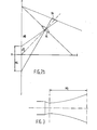
- Fig. 1 is illustrative of this principle. The beam of measuring radiation is projected onto a given point of an object's surface under inspection, which surface has been schematically indicated by hatching.
- the object of the proposals disclosed in the aforesaid publication is to increase the measuring rate by employing a so-called wavelength marking technique, without variations in the reflectivity of an object's surface under inspection introducing errors into the result of the measurement and without the results being ambiguous.
- a beam of measuring radiation of at least two different wavelengths use is made of a beam of measuring radiation of at least two different wavelengths; a raster pattern characterized by these wavelengths is projected onto the object's surface under inspection and the reflected radiation originating from this pattern is passed through separate wavelength - sensitive receiving channels to discrete detectors responsive to the respective wavelengths.
- the measurements are highly responsive to background radiation, which results in an adverse signal-to-noise ratio in respect of the output signal derived from the detectors; it is necessary to use at least two separate detector units each having a sensitivity matching one of the different wavelengths selected for the measurement; and the measurements are responsive to changes in colour of the object's surface under inspection.
- the DE-OS 3,110,644 A1 likewise describes the general principle of triangulation as a basis for the non-contact measurement of the distance between a reference plane and a given point of an object's surface.
- the object contemplated by the proposals disclosed in this publication is to provide a solution to the problem arising when the optical axis of the beam of measuring radiation is shifted as a result of drift, causing the point where this beam impinges upon the object's surface to be shifted too.
- Such a shift results in the introduction of measuring errors as in this prior art technique the only measuring information available is the distance between a first spot projected on the detector as corresponding to the zero or reference level and a second spot projected on this detector as corresponding to the point of the object's surface under inspection.
- the Selcom firm has developed a measuring system for the non-contact measurement of data relating to an object's surface.
- This known measuring system is likewise based on the triangulation principle.
- this measuring system likewise entails the drawback of being highly responsive to background radiation, which results in an adverse signal-to-noise ratio for the detector output signal.
- An additional drawback is the relatively poor lateral resolution, i.e. the resolution in planes normal to the beam of measuring radiation.
- a measuring system is based on the idea of substantially restricting the sensitivity to radiation of the reception section to a spatial volume having the form of an optimally slim beam extending substantially normal to an object's surface under inspection.
- a basic embodiment of the measuring system according to the invention is characterized in that the detector is sensitive to radiation only in a substantially linear area; and that only elements of the object's surface which are directly illuminated by the beam of measuring radiation, at any rate a longitudinal section thereof constituting the measuring zone, are imaged as corresponding, focussed spots on the linear radiation-sensitive area of the detector. In this manner, consequently, a thus-illuminated point of the object's surface is imaged as a sharply defined point on this area of the detector.
- any radiation originating from a region of the object's surface located outside the beam of measuring radiation will not result in the detector producing an, in that case spurious, output signal.
- this radiation will be imaged on the detector or an imaginary plane containing this detector as an out-of-focus spot, which does not result in the production of a significant signal at the detector output.
- the spot will be more out of focus as the region from which the radiation originates is farther away from the beam of measuring radiation.
- the resultant spot will be imaged, either in or out of focus, on the aforesaid imaginary detector plane though outside the linear radiation-sensitive detector area, so that such a spot does not result either in the production of a spurious detector output signal.
- An enhanced version of the above basic embodiment of the measuring system according to the invention is characterized in that a focussing lens included in the measuring radiation guide means is operative to so focus the beam of measuring radiation that, in the measuring zone, the cross-sectional area of this beam varies as a function of the distance as seen in the direction of the beam, so that all object spots formed within the measuring zone are imaged on the radiation-sensitive detector as spots of substantially and the position equal size.
- the power ⁇ of the focussing lens are such that the size of each object spot formed by the beam of measuring radiation within the measuring zone increases as the respective object spot is farther remote from the focussing lens. In this manner, the essentially linear variation of the measure of reduction introduced by the objective lens system of the detector, i.e.
- the extent to which an object spot is reduced when imaged on the detector is compensated for.
- the measure of reduction introduced by the detector objective lens system is preferably selected so that the size of a detector spot corresponding to an object spot is substantially equal to the area of a few detector elements. In this manner, the image definition and the lateral resolution are optimized throughout the entire measuring zone. Furthermore, as radiation originating from a surface region located outside the beam of measuring radiation will not cause a significant detector output signal, as explained above, a highly satisfactory signal-to-noise ratio is achieved.
- a measuring system according to the invention is especially suited for use in situations involving the presence of substantial sources of background radiation, such as high-intensity light sources.
- substantial sources of background radiation such as high-intensity light sources.
- An example of such a situation is the use of the measuring system in an automated welding process, in which case the measuring system should be immune to the high-intensity light radiation caused by the welding arc.
- a radttion source such as a laser, emitting monochromatic rad2Cion.
- the wavelength of this radiation is.selected to be in a portion of the spectrum where the presence of wavelength components of spurious background radiation to be expected, is small; while an optical bandpass filter is mounted within the spatial viewing angle of the detector, a wavelength of the pass-band, preferably a medium wavelength thereof, corresponding to the wavelength of the monochromatic radiation.
- a He-Ne laser appears to provide good results.
- a measuring system suiting this purpose is characterized in that the measuring radiation guide means are coupled to a drive means operative to have the beam of measuring radiation performascanning movement in a plane of measurement; and that the reflected radiation guide means are adapted to image object spots illuminated by the beam of measuring radiation during a scanning movement on a substantially linear radiation-sensitive area of the detector as focussed spots moving isochronally with the illuminated object spots.
- a further object of the invention is to provide a measuring system of the type described above, in which the adverse effect of false reflections can be eliminated by means of a simple structure.
- false reflections are formed by reflected radiation imaged on the respective detector as a result of the beam of measuring radiation incident on a given point of the object's surface being reflected to the detector by other surface elements located within or just outside the volume of the beam of measuring radiation.
- an embodiment of a measuring system suited to achieve the aforesaid object is characterized in that the reflected radiation guide means define, in addition to the first-named reception path, a second reception path forming with the first reception path a mirror-symmetrical configuration relative to a plane containing the beam of measuring radiation, this second reception path projecting reflected radiation originating from the respective object spot and guided along this path onto a second, separate radiation-sensitive detector; and that the outputs of the two radiation-sensitive detectors are coupled to a comparator for so comparing the output signals produced by these detectors that reflected radiation resulting from singular reflection of the beam of measuring radiation from the object's surface provides a useful output signal.
- An improved embodiment of a measuring system is characterized in that the reflected radiation guide means define a second reception path in addition to the first-named reception path, an initial portion of this second reception path as extending from a respective object spot forming with a corresponding initial portion of the first reception path a mirror-symmetrical configuration relative to a plane containing the beam of measuring radiation, this second reception path likewise projecting reflected radiation originating from the respective object spot and guided along this path onto the aforesaid radiation-sensitive detector; and that the output of this detector is coupled to a signal processing means operative to so process the detector output signals that a useful signal is provided in response to reflected radiation resulting from singular reflection of the beam of measuring radiation from the object's surface.
- a preferred embodiment of such a measuring system is characterized in that a portion of the second reception path is oriented to so deviate from a corresponding portion of the first reception path that reflected radiation originating from one and the same object spot as defined by the intersection of the plane containing the beam of measuring radiation and the respective object's surface is imaged on the detector via one reception path as a detector spot spaced a fixed distance from the detector spot imaged . on the detector via the other reception path as a projection of that object spot; and that the signal processing means are arranged to perform an auto-correlating function in respect of the detector output signal containing two discrete signal components spaced apart an interval corresponding to the aforesaid fixed distance.
- a first realization of such a measuring system is characterized in that the reflected radiation guide means include two prisms secured to each other to have one prism face in common, so that reflected radiation traversing one reception path is passed by this common prism face in partially undiffracted fashion into the direction of the detector and reflected radiation traversing the other reception path is partially reflected into the direction of this detector.
- a second realization of such a measuring system is characterized in that the aforesaid common prism face is tilted relative to the plane containing the beam of measuring radiation, the tilting angle being determinative of the aforesaid fixed distance.
- a measuring system is further characterized in that both reception paths include a reflector surface operative to direct reflected radiation originating from the object's surface onto the aforesaid common prism face; that each of these reflector surfaces is tilted through one and the same angle about a respective one of two intersecting axes extending mirror-symmetrically relative to the plane containing the beam of measuring radiation; and that the beam of measuring radiation is directed along the line of intersection of two planes via which this beam is imaged on the detector along the first and the second reception path.
- a structurally simple embodiment of a measuring system is characterized in that both reception paths include a reflector surface operative to direct reflected radiation originating from the object's surface onto the aforesaid prism face, and that each of these reflector surfaces forms together with the common prism face one of the two prisms.
- An alternative embodiment of a measuring system is characterized in that the reflected radiation guide means define a second reception path in addition to the first-named reception path, an initial portion of the second reception path as extending from a respective object spot forming with a corresponding initial portion of the first reception path a mirror-symmetrical configuration relative to a plane containing the beam of measuring radiation, both initial portions of this mirror-symmetrical configuration including a periodically active light radiation switch causing the respective optical path to successively be in blocked and transmissive state, so that reflected radiation is presented to the radiation-sensitive detector alternately via the one and the other reception path in accordance with a succession of time slots defining a first and a second time channel; and that the output of this detector is coupled to a signal processing means including a demodulator operative to convert the time-divided signals of the first time channel and of the second time channel into two spatially separated signals,and a comparator operative to so compare these two spatially separated signals with each other that reflected radiation resulting from singular reflection of the beam of measuring
- an additional criterion for distinguishing between "good” and “false” reflections can be obtained by introducing a predetermined characteristic into the beam of measuring radiation.
- a predetermined characteristic By means of, for example, a planoparallel plate it is possible to give the beam of measuring radiation an asymmetric intensity distribution.
- an embodiment based on this principle is characterized in that the transmission section includes beam-distorting means for irradiating a respective object's surface with a measuring beam of asymmetric intensity distribution; and that the reception section includes a signal processor operative to only pass those signal portions of a detector output signal applied thereto that correspond to image spots being a projection on the detector of the object spot located in the plane of the measuring beam that has an asymmetric intensity distribution as determined by the measuring beam.
- Fig. 2a schematically shows a basic embodiment of a measuring system according to the invention, which embodiment is characterized by the fact that the detector is irresponsive to spurious background radiation and only radiation originating from an object spot illuminated by the beam of measuring radiation is imaged in optimally focussed fashion on a linear radiation-sensitive area of the detector.
- the measuring zone MG is a zone bounded in the YZ plane in which the "depth" of surface regions of an object can be measured when "illuminated" by the measuring beam.
- FIG. 2a shows two of such object spots 01 and 02 produced when illuminating two surface elements of the object at different "depths" by means of a measuring beam incident along the Z axis.
- object spots such as 01 and 02, i.e. object spots defined as surface regions directly illuminated by the measuring beam, are imaged via a schematically shown objective lens system OL on a detector surface DV as focussed spots 01' and 02'.
- the detector comprises a substantially linear configuration of detector elements, a substantially linear radiation-sensitive area of detector elements being used for preference.
- a substantially linear radiation-sensitive area In a detector restricted to such a substantially linear radiation-sensitive area, all radiation originating from a surface region located a) within the .”plane" defined by the substantially linear measuring beam and the linear radiation-sensitive detector area, and b) outside the measuring beam, will be imaged on this radiation-sensitive detector area or on the extension thereof.
- the objective lens system OL is so constructed that such radiation, in sofar as originating from surface elements located within the viewing angle defined by the length of the radiation-sensitive detector area and the lens aperture though outside the measuring beam, is imaged on the radiation-sensitive detector area DG as out-of-focus spots, e.g.
- B1 is imaged as B1', whereas radiation originating from places located in the aforesaid "plane” though outside the aforesaid viewing angle is projected onto the extension of and. outside the radiation-sensitive area, such as e.g. B2 as B2'.
- the detector will produce an output signal which, if produced indeed, should be regarded as a spurious signal.
- This will also apply to radiation originating from surface regions located outside the aforesaid "plane”.
- the surface region A1 or A2 located outside the aforesaid plane i.e. the XZ plane in Fig.
- the surface regions illuminated by the measuring beam are viewed from the detector at different angles, such as e, in dependence upon the "depth" in the Z direction to be measured, and the measure of imaging, i.e. the extent to which an object spot illuminated by the measuring beam is reduced when imaged on the detector, likewise varies as a function of the Z coordinate over the measuring zone MG, the detector plane DG and hence the actual detector DG is mounted at a given angle relative to the optical axis 01-P thereof.
- Fig. 2b illustrating the situation obtaining in the XZ plane of Fig. 2a.
- a measuring system it is further contemplated to optimize the lateral resolution throughout the measuring zone, i.e. the resolution in planes transverse to the measuring beam, to the effect that irrespective of the position at which an object spot is located within the measuring beam, this object spot is imaged on the detector as an image spot having a cross-sectional area corresponding to that of a few, e.g. two to four, detector cells (a detector cell has dimensions of e.g. 25 x 26 / um).
- Fig. 3 shows a satisfactory shape of the measuring beam in longitudinal section. As appears from Fig. 3, the measuring beam will be essentially divergent in the direction of radiation.
- a measuring system it is thus achieved that the substantially linear variation of the measure of imaging as a function of the distance between the focussing lens for the measuring beam and a respective object spot caused by the illumination of a surface element by this measuring beam, which distance varies in the Z direction, is compensated for by the variation in the size of the object spot as a function of this distance as achieved as a result of the particular beam shape chosen. Consequently, the choice of the particular shape of the measuring beam results in the size of the object spot being increased in proportion as the measure of magnification is decreased as a function of the distance in the Z direction. In this manner, surface elements illuminated by the measuring beam throughout the entire measuring zone thereof can be imaged on the radiation-sensitive detector area as spots of substantially equal size.
- the transmission section of the measuring system is arranged to realize movement of the measuring beam over the object's surface, preferably in accordance with a succession of sweeping movements in mutually parallel planes, for example planes parallel to the YZ plane of Fig. 2a.
- the measuring beam is so shifted in, for example, the X direction of Fig. 2a that a next sweep is performed in a plane parallel to the plane of the previous sweep, etc.
- an object's surface can be systematically scanned, for example at a measuring rate of 115 Az measurements per sweep and a scanning rate of 10 sweeps per second.
- the reception section of the measuring system is so arranged that the reflected radiation guide means are operative to image the surface elements successively illuminated during a sweeping movement of the measuring beam on the radiation-sensitive detector area as spots isochronously moving and corresponding with these elements.
- the illuminated object spot is sharply imaged on the radiation-sensitive detector area as a corresponding, well-defined spot.
- the desired sweeping movement of the measuring beam is achieved by means of a measuring beam mirror mounted for pivotal movement about a shaft, the measuring beam produced by a fixedly mounted focussing lens and radiation source being directed onto this mirror.
- the shaft is coupled to a drive mechanism arranged for imparting a reciprocatory sweeping movement through a desired sweep angle to this shaft and hence the measuring beam mirror.
- the measuring beam can be swept through a desired angular distance, for example in the YZ plane in the arrangement of Fig. 2a.
- a preferred embodiment additionally includes a mirror for receiving reflected radiation, which receiving mirror is likewise mounted for pivotal movement about the aforesaid shaft and is so mounted thereon relative to the measuring beam mirror that, when the drive mechanism is operative, the measuring beam mirror and the receiving mirror perform isochronous, reciprocatory sweeping movements.
- the surface elements illuminated by the measuring beam mirror are viewed by the receiving mirror, and the reflected radiation originating from these surface elements is passed via this receiving mirror and via a fixedly mounted objective lens to the likewise fixedly mounted detector.
- the arrangement further includes a measuring beam position sensor producing position signals representative of the instantaneous measuring beam position. Data necessary for the measurement of the surface profile are derived from such position signals.
- the object spots illuminated by the measuring beam during the sweeping movement are isochronously followed by the reception section, so that spots corresponding to the respective object spots are imaged on the detector.
- the reception section is substantially only responsive to reflected radiation originating from the spatial volume bounded by the measuring beam.
- sources of spurious radiation located outside this volume area have practically no effect on the measurement. This implies that the measuring system will have a highly satisfactory signal-to-noise ratio.
- reception section It is not necessary to have one or more components of the reception section move along with the measuring beam during a scanning procedure, as this is the case with the receiving mirror of the embodiment described above. In principle, the same result can be achieved by using a reception section fixedly mounted in space and lacking moving components. In order to achieve a proper signal-to-noise ratio, however, it is then necessary to employ a two-dimensional detector with an associated control means operative to move a linear radiation-sensitive detector area in isochronism with the measuring beam in this two-dimensional detector plane.
- the measuring system is to be used in the vicinity of substantial sources of spurious radiation, for example when the measuring system according to the invention is employed in an automated welding process, additional steps may advantageously be taken to eliminate the effect of such spurious radiation on the detector.
- additional steps may advantageously be taken to eliminate the effect of such spurious radiation on the detector.
- use is made of the fact that the spectrum of spurious light radiation will exhibit "valley zones" and that sources of monochromatic radiation are available emitting radiation of a wavelength corresponding to such a zone.
- a He-Ne laser is used as a source of monochromatic radiation
- an optical bandpass filter for examle an interference filter, being mounted within the spatial viewing angle of the detector.
- the pass-band of this filter includes the wavelength corresponding to that of the radiation emitted by the laser. The effect of spurious radiation can efficiently be eliminated in this manner.
- the reflected radiation is passed to the detector via a single optical transmission path.
- This renders it possible that so-called false reflections, which are caused by the measuring beam being reflected more than one time from the object's surface into the direction of the detector, have an adverse effect on the result of the measurement. It is therefore recommended to modify the above-described embodiments so, that the effect of such false reflections can be efficiently eliminated.
- the following discusses a number of examples of embodiments suiting such a purpose.
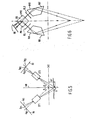
- the embodiment of a measuring system according to the invention as schematically shown in Fig. 4 comprises a source 1 for producing measuring radiation.
- a source 1 for producing measuring radiation for producing measuring radiation.
- optical radiation particularly radiation produced by a laser.
- the measuring radiation i.e. light radiation
- the source 1 is directed and projected onto an object's surface Z under inspection in the form of a measuring beam 3.
- a portion of object's surface Z is schematically indicated by hatching.
- the measuring beam produces a light spot at point P of the object's surface.
- the measuring system further includes a first reflected light transmission channel 4 and a second reflected light transmission channel 5.
- Each of these reflected light transmission channels is optically coupled to the receiving end of an associated light- sensitive detector 6 and 7, respectively, capable of converting received reflected light into a corresponding signal of different form, preferably an electrical signal.
- the two transmission channels are identical and define a light path configu - ration that is mirror-symmetrical relative to an imaginary "measuring beam plane" containing the measuring beam and extending normal to the plane of the drawing.
- a measuring light spot whose place P is defined by the intersection of the measuring beam plane and the object's surface is imaged on the two detectors 6 and 7 as detector spots I p1 and ⁇ P2 , respectively, spaced equal distances from detector spot positions ⁇ 01 and ⁇ 02 , respectively.
- The:outputs of detectors 6 and 7, respectively are connected to the first and second input, respectively, of a comparator 8.
- each one of detectors 6 and 7 is a charge-coupled device (CCD) having a given number of detector cells.
- the contents of these two CCDs are serially shifted out, so that a time function signal is produced at the output of the respective detector, in which signal the light spot position, such as ⁇ P1 or ⁇ P2 , is represented as a time interval.
- the comparator is operative to multiply the synchronized detector signals applied thereto by each other. This implies that an object light spot located in the measuring beam plane, i.e. the plane of symmetry, will cause the production of a significant output signal at the output of the comparator.
- Fig. 5 schematically shows a situation in which not only an object light spot P located in the measuring beam plane (i.e. the plane of symmetry extending normal to the plane of the drawing and containing the measuring beam MB) but also a false reflection R, i.e. a spurious spot located outside this plane of symmetry,are projected as image spots onto the two detectors D1 and D2 via the respective reception paths OT1 and OT2.
- a false reflection R i.e. a spurious spot located outside this plane of symmetry
- the multiplication performed to the two detector output signals applied to the comparator results in the production of a product signal at the output of this comparator, of which product signal the signal portion corresponding to the product of image spots ⁇ P1 and 6 P2 is clearly distinct from the remaining portion of this product signal. Consequently, the arrangement in question has a discriminating capacity in respect of false reflections or spurious signals caused by object spots located outside the plane of symmetry.
- Fig. 6 schematically shows such a basic embodiment of a measuring system according to the invention employing a single detector. In principle, this embodiment is identical to that shown in Fig. 4.
- the embodiment of Fig. 6 includes a first reflected radiation transmission path and a second reflected radiation transmission path so arranged and oriented relative to the measuring beam plane or plane of symmetry that an essentially mirror-symmetrical configuration is formed.
- the first and second transmission paths each include an entrance light guide IG1 and IG2,respectively, each having a light reflector surface RV1 and RV2, respectively, operative to receive reflected radiation from the object's surface and to deflect this radiation into the direction of an associated objective lens OL1 and OL2, respectively.
- the two objective lenses are optically coupled to a beam splitter BS.
- This beam splitter is composed of two prisms PR1 and PR2 cemented to each other to have one prism face in common. This common prism face is partially reflective to reflected radiation emanating from objective lens OL1 and partially transmissive to reflected radiation emanating from objective lens OL2.
- the construction is such that both radiation - reflected by the common prism face and radiation transmitted by this face are directed to the detector GD common to both reflected radiation transmission paths. If this arrangement is an essentially perfect mirror-symmetrical configuration, reflected radiation from each object spot located in the measuring beam plane or plane of symmetry is imaged via the two transmission paths on the detector as a single spot distinguishing itself by its intensity from any other image spots formed on this detector as a result of false reflections or spurious signals. In principle, in this manner a discriminating capacity is achieved which permits "good" reflections to be distinguished from false reflections or spurious signals. However, such a discriminating capacity may be made more efficient and practical by introducing, in accordance with a further aspect of the invention, a slight asymmetry into the configuration formed by the two reflected radiation transmission paths.
- such an asymmetry can be obtained by mounting the objective lenses OL1 and OL2 at such a fixed optical distance from the common detector GD that reflected radiation from an object spot located in the plane of symmetry is each time imaged on the detector as two discrete image spots spaced a fixed distance apart.
- Reflected radiation or spurious radiation originating from a point located outside this plane of symmetry though within the "field angle" of the detector is imaged on this detector as one or more image spots which are not spaced apart by such a fixed distance.
- the output signal obtained by reading out the detector has to be multiplied by a predetermined filter function having the form of the detector signal to be expected, i.e. a signal having two signal peaks spaced a fixed distance apart.
- the detector output signal can be optimally filtered by an auto-correlating operation.
- the detector signal f(x) is multiplied by the signal f(x+ AT ) for each signal segment,integration of these products resulting in a signal being a function of aT. In this manner, false reflections and spurious signals can be distinguished from good reflections as such false reflections are suppressed by this auto-correlating operation.
- the two reflector surfaces RV1 and RV2 which extend normal to the plane of the drawing in the situation illustrated in Fig. 6, may be tilted through equal angles. Seen in Fig. 6, the axes about which the reflector surfaces are to be tilted are the intersecting lines of the respective reflector surfaces and the plane of the drawing.
- Such a tilted mounting of the reflector surfaces actually results in the definition of a straight line extending into space, in particular a straight line extending in the measuring beam plane and enclosing an acute angle with the plane of the drawing. Only radiation reflected along such a straight line can reach the detector via the two transmission paths. Consequently, by such a tilted mounting of the two reflectors it is achieved that the area from which reflected radiation can impinge upon the detector via the two transmission paths is greatly reduced. Self-evidently, in this modification the measuring beam is directed along the aforesaid straight line.
- Fig. 6 entails the practical drawback that, when components IG1, IG2, OL1, OL2 and BS are united into a single unit, a relatively voluminous assembly is obtained. This is due to the fact that the use of the triangulation principle requires a certain minimum angle at which the object's surface is viewed and hence a certain minimum width of the triangle's base as defined by the two entrance light guides. Moreover, the embodiment of Fig. 6 requires the presence of an objective lens in each reflected radiation transmission path.
- Fig. 7 schematically shows a preferred embodiment of the invention lacking the above-mentioned drawbacks inherent in the embodiment of Fig. 6.
- the operation of this preferred embodiment is equivalent to that of the embodiment of Fig. 6.
- Reflected radiation schematically indicated by R and T as originating from each object spot located in the measuring beam plane emanates at a fixed aperture angle 26 from the composite prism uniting the functions of the components shown in Fig. 6, apart from the detector and the two objective lenses.
- the angle indicated by A is equal to 45° + 6, while the angle indicated by A is equal to 45° - 6.
- the two time channels are alternately applied to the detector, so that a single detector output signal will contain time-separated information of the two transmission paths.
- the signal processor connected to the detector output includes a demodulator operative to form two spatially separated electrical signals from the singular electrical signal applied thereto, one of these two electrical signals corresponding to one transmission path and the other electrical signal corresponding to the other transmission path. These two spatially separated electrical signals can be compared to each other by means of a comparator so as to distinguish good reflections from false reflections.
- a measuring system use may be made of a measuring beam having a predetermined, specific characteristic introduced therein, in combination with a waveform-sensitive filter, such as a so-called matched filter, as a component of the means for processing and filtering, respectively, the detector output signals.
- a waveform-sensitive filter such as a so-called matched filter
- the intensity distribution of the measuring beam can be characterized by a Gaussian curve.
- An asymmetric intensity distribution having a desired distribution curve can be obtained by, for example, mounting an appropriate mask in the optical path of the measuring beam.
- the matched filter is so dimensioned that its pass-waveform corresponds to the signal waveform to be expected when an object spot formed by such an "asymmetric" measuring beam is imaged on the detector.
- an object spot located in the plane of symmetry i.e. an object spot representative of a good reflection,will result in a detector spot and hence a detector output signal having a significant asymmetric peak shape.
- Object spots located outside the plane of symmetry result in reflected radiation which, when imaged on the detector, causes signal waveforms at the detector output that fail to correspond to the pass- characteristic of the matched filter.
- a false reflection implies a twofold reflection of the measuring beam from the object's surface, such a false reflection will result in a detector spot and hence a detector output signal having a peak shape that is the mirror image of the peak shape associated with a good reflection. Consequently, the asymmetric intensity distribution of the measuring beam provides a clear criterion on the basis whereof it can be ascertained with simple means whether a detector output signal is representative of a good or a false reflection. Thus such false reflections can efficiently be distinguished from good reflections.
Priority Applications (1)
| Application Number | Priority Date | Filing Date | Title |
|---|---|---|---|
| AT84200902T ATE44093T1 (de) | 1983-06-22 | 1984-06-21 | Messsystem gemaess dem triangulationsprinzip, zur dimensionskontrolle an objekten. |
Applications Claiming Priority (2)
| Application Number | Priority Date | Filing Date | Title |
|---|---|---|---|
| NL8302228 | 1983-06-22 | ||
| NL8302228A NL8302228A (nl) | 1983-06-22 | 1983-06-22 | Meetstelsel voor het onder gebruikmaking van een op driehoeksmeting berustend principe, contactloos meten van een door een oppervlakcontour van een objectvlak gegeven afstand tot een referentieniveau. |
Publications (3)
| Publication Number | Publication Date |
|---|---|
| EP0134597A1 true EP0134597A1 (de) | 1985-03-20 |
| EP0134597B1 EP0134597B1 (de) | 1989-06-14 |
| EP0134597B2 EP0134597B2 (de) | 1993-06-09 |
Family
ID=19842055
Family Applications (1)
| Application Number | Title | Priority Date | Filing Date |
|---|---|---|---|
| EP84200902A Expired - Lifetime EP0134597B2 (de) | 1983-06-22 | 1984-06-21 | Messsystem gemäss dem Triangulationsprinzip, zur Dimensionskontrolle an Objekten |
Country Status (12)
| Country | Link |
|---|---|
| US (1) | US4701049A (de) |
| EP (1) | EP0134597B2 (de) |
| JP (1) | JPS6036908A (de) |
| KR (1) | KR920009018B1 (de) |
| AT (1) | ATE44093T1 (de) |
| AU (1) | AU570474B2 (de) |
| BR (1) | BR8403060A (de) |
| CA (1) | CA1236904A (de) |
| DE (1) | DE3478714D1 (de) |
| IL (1) | IL72183A (de) |
| NL (1) | NL8302228A (de) |
| ZA (1) | ZA844707B (de) |
Cited By (8)
| Publication number | Priority date | Publication date | Assignee | Title |
|---|---|---|---|---|
| GB2176963A (en) * | 1985-06-05 | 1987-01-07 | Plessey Co Plc | Locating power source for rail vehicle |
| EP0214120A2 (de) * | 1985-08-28 | 1987-03-11 | IGM Industriegeräte- und Maschinenfabriksgesellschaft mbH | Verfahren zum Erfassen der Position und Geometrie von Werkstückoberflächen |
| DE3702691A1 (de) * | 1986-06-14 | 1987-12-17 | Zeiss Carl Fa | Beruehrungsloser abstandssensor |
| EP0256968A1 (de) * | 1986-07-23 | 1988-02-24 | MANNESMANN Aktiengesellschaft | Automatisches Verfahren zur berührungslosen dreidimensionalen Vermessung von Objekten grosser Ausdehnung |
| EP0346015A2 (de) * | 1988-06-04 | 1989-12-13 | Fujitsu Limited | Optisches System zur Ermittlung einer dreidimensionalen Form |
| GB2235286A (en) * | 1989-07-23 | 1991-02-27 | Elor Optronics Limited | Optical system for measuring location |
| US5104216A (en) * | 1988-12-05 | 1992-04-14 | Igm Industriegerate- Und Maschinenfabriksgesellschaft Mbh | Process for determining the position and the geometry of workpiece surfaces |
| WO1999040390A1 (fr) * | 1998-02-06 | 1999-08-12 | Premium Instruments S.A. | Procede et dispositif de mesure de la forme et/ou de la position d'un profil d'une surface d'un produit en defilement |
Families Citing this family (129)
| Publication number | Priority date | Publication date | Assignee | Title |
|---|---|---|---|---|
| US4916302A (en) * | 1985-02-09 | 1990-04-10 | Canon Kabushiki Kaisha | Apparatus for and method of measuring distances to objects present in a plurality of directions |
| JPS6227613A (ja) * | 1985-07-29 | 1987-02-05 | Nippon Kogaku Kk <Nikon> | 位置検出装置 |
| AU590326B2 (en) * | 1985-09-26 | 1989-11-02 | Unisearch Limited | Robot vision & optical location systems |
| US4939439A (en) * | 1985-09-26 | 1990-07-03 | Unisearch Limited | Robot vision and optical location systems |
| JPS62259756A (ja) * | 1986-05-04 | 1987-11-12 | Takegawa Tekko Kk | バリ取り装置における加工材の選別装置 |
| JPS63180810A (ja) * | 1987-01-22 | 1988-07-25 | Matsushita Electric Works Ltd | 高さ検出方式 |
| US4786815A (en) * | 1987-02-12 | 1988-11-22 | K. J. Law Engineers, Inc. | Non-contact sensor with particular utility for measurement of road profile |
| US4894551A (en) * | 1987-06-05 | 1990-01-16 | Anima Corporation | Sectional form measuring apparatus |
| GB8728150D0 (en) | 1987-12-02 | 1988-01-06 | Inst Of Neurology Queen Square | Head fixation apparatus |
| US5251127A (en) * | 1988-02-01 | 1993-10-05 | Faro Medical Technologies Inc. | Computer-aided surgery apparatus |
| DE3805548A1 (de) * | 1988-02-23 | 1989-08-31 | Thiedig Ullrich | Optische fernmesseinrichtung |
| GB2222047A (en) * | 1988-07-25 | 1990-02-21 | Unisearch Ltd | Optical mapping of field of view and information storage |
| US5028799A (en) * | 1988-08-01 | 1991-07-02 | Robotic Vision System, Inc. | Method and apparatus for three dimensional object surface determination using co-planar data from multiple sensors |
| US4939379A (en) * | 1989-02-28 | 1990-07-03 | Automation Research Technology, Inc. | Contour measurement using time-based triangulation methods |
| NL8902314A (nl) * | 1989-09-15 | 1991-04-02 | Michiel Kassies | Werkwijze en inrichting voor het detecteren van een voorwerp. |
| FR2652928B1 (fr) | 1989-10-05 | 1994-07-29 | Diadix Sa | Systeme interactif d'intervention locale a l'interieur d'une zone d'une structure non homogene. |
| US5052854A (en) * | 1990-04-19 | 1991-10-01 | Sfo Enterprises | Highway guidance vehicle systems |
| CA2017518A1 (en) * | 1990-05-24 | 1991-11-24 | Her Majesty The Queen, In Right Of Canada, As Represented By The Ministe R Of The National Research Council Of Canada | Colour-range imaging |
| US5061062A (en) * | 1990-07-02 | 1991-10-29 | General Electric Company | Focus spot size controller for a variable depth range camera |
| US5082362A (en) * | 1990-07-02 | 1992-01-21 | General Electric Company | Zoom lens for a variable depth range camera |
| US5198877A (en) * | 1990-10-15 | 1993-03-30 | Pixsys, Inc. | Method and apparatus for three-dimensional non-contact shape sensing |
| US6347240B1 (en) | 1990-10-19 | 2002-02-12 | St. Louis University | System and method for use in displaying images of a body part |
| CA2094251C (en) * | 1990-10-19 | 1999-01-19 | Richard D. Bucholz | Surgical probe locating system for head use |
| US5662111A (en) * | 1991-01-28 | 1997-09-02 | Cosman; Eric R. | Process of stereotactic optical navigation |
| US6167295A (en) * | 1991-01-28 | 2000-12-26 | Radionics, Inc. | Optical and computer graphic stereotactic localizer |
| US6675040B1 (en) | 1991-01-28 | 2004-01-06 | Sherwood Services Ag | Optical object tracking system |
| US6006126A (en) * | 1991-01-28 | 1999-12-21 | Cosman; Eric R. | System and method for stereotactic registration of image scan data |
| US6405072B1 (en) | 1991-01-28 | 2002-06-11 | Sherwood Services Ag | Apparatus and method for determining a location of an anatomical target with reference to a medical apparatus |
| US5603318A (en) | 1992-04-21 | 1997-02-18 | University Of Utah Research Foundation | Apparatus and method for photogrammetric surgical localization |
| CA2142338C (en) | 1992-08-14 | 1999-11-30 | John Stuart Bladen | Position location system |
| FR2703932B1 (fr) * | 1993-04-16 | 1995-07-07 | Materiel Arboriculture | Procede et dispositif de tri automatique de produits, notamment de fruits et legumes. |
| EP0700269B1 (de) * | 1993-04-22 | 2002-12-11 | Image Guided Technologies, Inc. | Anordnung zur bestimmung der gegenseitigen lage von körpern |
| EP0997109B1 (de) * | 1993-04-26 | 2003-06-18 | ST. Louis University | Anzeige der Lage einer chirurgischen Sonde |
| US5803089A (en) | 1994-09-15 | 1998-09-08 | Visualization Technology, Inc. | Position tracking and imaging system for use in medical applications |
| US5829444A (en) | 1994-09-15 | 1998-11-03 | Visualization Technology, Inc. | Position tracking and imaging system for use in medical applications |
| DE19581099B4 (de) * | 1994-09-28 | 2006-07-27 | William Richard Fright | Optisches Oberflächenabtastgerät und Vermessungsverfahren |
| ATE320226T1 (de) | 1994-10-07 | 2006-04-15 | Univ St Louis | Chirurgische navigationsanordnung einschliesslich referenz- und ortungssystemen |
| US6978166B2 (en) | 1994-10-07 | 2005-12-20 | Saint Louis University | System for use in displaying images of a body part |
| US6167145A (en) * | 1996-03-29 | 2000-12-26 | Surgical Navigation Technologies, Inc. | Bone navigation system |
| US6408107B1 (en) | 1996-07-10 | 2002-06-18 | Michael I. Miller | Rapid convolution based large deformation image matching via landmark and volume imagery |
| US6226418B1 (en) | 1997-11-07 | 2001-05-01 | Washington University | Rapid convolution based large deformation image matching via landmark and volume imagery |
| US6226548B1 (en) | 1997-09-24 | 2001-05-01 | Surgical Navigation Technologies, Inc. | Percutaneous registration apparatus and method for use in computer-assisted surgical navigation |
| US6021343A (en) | 1997-11-20 | 2000-02-01 | Surgical Navigation Technologies | Image guided awl/tap/screwdriver |
| JPH11151229A (ja) * | 1997-11-21 | 1999-06-08 | Kdk Corp | 非接触非侵襲測定方法及び装置 |
| US6348058B1 (en) | 1997-12-12 | 2002-02-19 | Surgical Navigation Technologies, Inc. | Image guided spinal surgery guide, system, and method for use thereof |
| US6477400B1 (en) | 1998-08-20 | 2002-11-05 | Sofamor Danek Holdings, Inc. | Fluoroscopic image guided orthopaedic surgery system with intraoperative registration |
| US6122039A (en) * | 1998-10-28 | 2000-09-19 | Banner Engineering Corp. | Method and apparatus to detect and report object displacement utilizing optical triangulation principles |
| US6633686B1 (en) | 1998-11-05 | 2003-10-14 | Washington University | Method and apparatus for image registration using large deformation diffeomorphisms on a sphere |
| US6470207B1 (en) | 1999-03-23 | 2002-10-22 | Surgical Navigation Technologies, Inc. | Navigational guidance via computer-assisted fluoroscopic imaging |
| US6491699B1 (en) | 1999-04-20 | 2002-12-10 | Surgical Navigation Technologies, Inc. | Instrument guidance method and system for image guided surgery |
| US6702832B2 (en) | 1999-07-08 | 2004-03-09 | Med Logics, Inc. | Medical device for cutting a cornea that has a vacuum ring with a slitted vacuum opening |
| US6699285B2 (en) | 1999-09-24 | 2004-03-02 | Scieran Technologies, Inc. | Eye endoplant for the reattachment of a retina |
| US7366562B2 (en) | 2003-10-17 | 2008-04-29 | Medtronic Navigation, Inc. | Method and apparatus for surgical navigation |
| US8644907B2 (en) | 1999-10-28 | 2014-02-04 | Medtronic Navigaton, Inc. | Method and apparatus for surgical navigation |
| US6381485B1 (en) | 1999-10-28 | 2002-04-30 | Surgical Navigation Technologies, Inc. | Registration of human anatomy integrated for electromagnetic localization |
| US11331150B2 (en) | 1999-10-28 | 2022-05-17 | Medtronic Navigation, Inc. | Method and apparatus for surgical navigation |
| US6499488B1 (en) | 1999-10-28 | 2002-12-31 | Winchester Development Associates | Surgical sensor |
| US8239001B2 (en) | 2003-10-17 | 2012-08-07 | Medtronic Navigation, Inc. | Method and apparatus for surgical navigation |
| US6474341B1 (en) | 1999-10-28 | 2002-11-05 | Surgical Navigation Technologies, Inc. | Surgical communication and power system |
| US6493573B1 (en) | 1999-10-28 | 2002-12-10 | Winchester Development Associates | Method and system for navigating a catheter probe in the presence of field-influencing objects |
| US6428508B1 (en) | 2000-02-01 | 2002-08-06 | Enlighten Technologies, Inc. | Pulsed vacuum cataract removal system |
| US6725080B2 (en) | 2000-03-01 | 2004-04-20 | Surgical Navigation Technologies, Inc. | Multiple cannula image guided tool for image guided procedures |
| US6535756B1 (en) | 2000-04-07 | 2003-03-18 | Surgical Navigation Technologies, Inc. | Trajectory storage apparatus and method for surgical navigation system |
| US6663644B1 (en) | 2000-06-02 | 2003-12-16 | Med-Logics, Inc. | Cutting blade assembly for a microkeratome |
| US7085400B1 (en) | 2000-06-14 | 2006-08-01 | Surgical Navigation Technologies, Inc. | System and method for image based sensor calibration |
| KR100679178B1 (ko) * | 2000-07-07 | 2007-02-07 | 주식회사 지에스인스트루먼트 | 수평 및 수직 기준 빔 발생 장치 |
| US6425905B1 (en) | 2000-11-29 | 2002-07-30 | Med-Logics, Inc. | Method and apparatus for facilitating removal of a corneal graft |
| US7311700B2 (en) | 2000-11-29 | 2007-12-25 | Med-Logics, Inc. | LASIK laminar flow system |
| US6636757B1 (en) | 2001-06-04 | 2003-10-21 | Surgical Navigation Technologies, Inc. | Method and apparatus for electromagnetic navigation of a surgical probe near a metal object |
| US7136171B2 (en) * | 2001-12-19 | 2006-11-14 | General Electric Company | Method for the extraction of image features caused by structure light using template information |
| US6947786B2 (en) | 2002-02-28 | 2005-09-20 | Surgical Navigation Technologies, Inc. | Method and apparatus for perspective inversion |
| US6990368B2 (en) | 2002-04-04 | 2006-01-24 | Surgical Navigation Technologies, Inc. | Method and apparatus for virtual digital subtraction angiography |
| US7998062B2 (en) | 2004-03-29 | 2011-08-16 | Superdimension, Ltd. | Endoscope structures and techniques for navigating to a target in branched structure |
| AR039475A1 (es) * | 2002-05-01 | 2005-02-23 | Wyeth Corp | 6-alquiliden-penems triciclicos como inhibidores de beta-lactamasa |
| US7697972B2 (en) | 2002-11-19 | 2010-04-13 | Medtronic Navigation, Inc. | Navigation system for cardiac therapies |
| US7599730B2 (en) | 2002-11-19 | 2009-10-06 | Medtronic Navigation, Inc. | Navigation system for cardiac therapies |
| US7542791B2 (en) | 2003-01-30 | 2009-06-02 | Medtronic Navigation, Inc. | Method and apparatus for preplanning a surgical procedure |
| US7660623B2 (en) | 2003-01-30 | 2010-02-09 | Medtronic Navigation, Inc. | Six degree of freedom alignment display for medical procedures |
| US7570791B2 (en) | 2003-04-25 | 2009-08-04 | Medtronic Navigation, Inc. | Method and apparatus for performing 2D to 3D registration |
| US7313430B2 (en) | 2003-08-28 | 2007-12-25 | Medtronic Navigation, Inc. | Method and apparatus for performing stereotactic surgery |
| EP2316328B1 (de) | 2003-09-15 | 2012-05-09 | Super Dimension Ltd. | Umhüllungsvorrichtung zur Fixierung von Bronchoskopen |
| ES2387026T3 (es) | 2003-09-15 | 2012-09-11 | Super Dimension Ltd. | Dispositivo de fijación envolvente para utilizarse con broncoscopios |
| US7835778B2 (en) | 2003-10-16 | 2010-11-16 | Medtronic Navigation, Inc. | Method and apparatus for surgical navigation of a multiple piece construct for implantation |
| US7840253B2 (en) | 2003-10-17 | 2010-11-23 | Medtronic Navigation, Inc. | Method and apparatus for surgical navigation |
| US7101053B2 (en) * | 2004-01-15 | 2006-09-05 | Associated Universities, Inc. | Multidirectional retroreflectors |
| US8764725B2 (en) | 2004-02-09 | 2014-07-01 | Covidien Lp | Directional anchoring mechanism, method and applications thereof |
| US7567834B2 (en) | 2004-05-03 | 2009-07-28 | Medtronic Navigation, Inc. | Method and apparatus for implantation between two vertebral bodies |
| US7636595B2 (en) | 2004-10-28 | 2009-12-22 | Medtronic Navigation, Inc. | Method and apparatus for calibrating non-linear instruments |
| JP4549958B2 (ja) | 2005-02-09 | 2010-09-22 | パナソニック株式会社 | 遅延ロックドループ回路 |
| US7835784B2 (en) | 2005-09-21 | 2010-11-16 | Medtronic Navigation, Inc. | Method and apparatus for positioning a reference frame |
| US9168102B2 (en) | 2006-01-18 | 2015-10-27 | Medtronic Navigation, Inc. | Method and apparatus for providing a container to a sterile environment |
| US8112292B2 (en) | 2006-04-21 | 2012-02-07 | Medtronic Navigation, Inc. | Method and apparatus for optimizing a therapy |
| US8660635B2 (en) | 2006-09-29 | 2014-02-25 | Medtronic, Inc. | Method and apparatus for optimizing a computer assisted surgical procedure |
| US7768633B2 (en) * | 2007-04-05 | 2010-08-03 | Asti Holdings Limited | Multiple surface inspection system and method |
| US8905920B2 (en) | 2007-09-27 | 2014-12-09 | Covidien Lp | Bronchoscope adapter and method |
| WO2009122273A2 (en) | 2008-04-03 | 2009-10-08 | Superdimension, Ltd. | Magnetic interference detection system and method |
| WO2009147671A1 (en) | 2008-06-03 | 2009-12-10 | Superdimension Ltd. | Feature-based registration method |
| US8218847B2 (en) | 2008-06-06 | 2012-07-10 | Superdimension, Ltd. | Hybrid registration method |
| US8932207B2 (en) | 2008-07-10 | 2015-01-13 | Covidien Lp | Integrated multi-functional endoscopic tool |
| US8165658B2 (en) | 2008-09-26 | 2012-04-24 | Medtronic, Inc. | Method and apparatus for positioning a guide relative to a base |
| JP5206344B2 (ja) * | 2008-11-14 | 2013-06-12 | オムロン株式会社 | 光学式計測装置 |
| US8175681B2 (en) | 2008-12-16 | 2012-05-08 | Medtronic Navigation Inc. | Combination of electromagnetic and electropotential localization |
| DE102009014463A1 (de) * | 2009-03-23 | 2010-09-30 | Siemens Medical Instruments Pte. Ltd. | Vorrichtung und Verfahren zum Messen der Distanz zum Trommelfell |
| US8611984B2 (en) | 2009-04-08 | 2013-12-17 | Covidien Lp | Locatable catheter |
| US8494613B2 (en) | 2009-08-31 | 2013-07-23 | Medtronic, Inc. | Combination localization system |
| US8494614B2 (en) | 2009-08-31 | 2013-07-23 | Regents Of The University Of Minnesota | Combination localization system |
| US8641942B2 (en) | 2010-05-12 | 2014-02-04 | Corning Incorporated | Laser scanning systems and methods for measuring extruded ceramic logs |
| WO2011159834A1 (en) | 2010-06-15 | 2011-12-22 | Superdimension, Ltd. | Locatable expandable working channel and method |
| ITSA20110016A1 (it) * | 2011-07-20 | 2011-10-19 | Claudia Covucci | Dispositivo per la rilevazione della coordinata della profondità (z) in un campo tridimensionale cartesiano. |
| US8928874B2 (en) | 2012-02-24 | 2015-01-06 | Mitutoyo Corporation | Method for identifying abnormal spectral profiles measured by a chromatic confocal range sensor |
| US8860931B2 (en) * | 2012-02-24 | 2014-10-14 | Mitutoyo Corporation | Chromatic range sensor including measurement reliability characterization |
| US10365371B2 (en) * | 2013-12-31 | 2019-07-30 | Lumens Co., Ltd. | Multi-position sensing apparatus |
| JP6279907B2 (ja) * | 2014-01-15 | 2018-02-14 | 池上通信機株式会社 | 画像ピックアップヘッドおよび3次元形状計測装置 |
| US10952593B2 (en) | 2014-06-10 | 2021-03-23 | Covidien Lp | Bronchoscope adapter |
| WO2016190921A1 (en) | 2015-02-05 | 2016-12-01 | Associated Universities, Inc. | Fiber optic based laser range finder |
| US10426555B2 (en) | 2015-06-03 | 2019-10-01 | Covidien Lp | Medical instrument with sensor for use in a system and method for electromagnetic navigation |
| US9962134B2 (en) | 2015-10-28 | 2018-05-08 | Medtronic Navigation, Inc. | Apparatus and method for maintaining image quality while minimizing X-ray dosage of a patient |
| US10478254B2 (en) | 2016-05-16 | 2019-11-19 | Covidien Lp | System and method to access lung tissue |
| CN106352801B (zh) * | 2016-10-17 | 2018-03-02 | 海伯森技术(深圳)有限公司 | 一种激光三角位移传感器及其非线性误差的修正方法 |
| US10638952B2 (en) | 2016-10-28 | 2020-05-05 | Covidien Lp | Methods, systems, and computer-readable media for calibrating an electromagnetic navigation system |
| US10792106B2 (en) | 2016-10-28 | 2020-10-06 | Covidien Lp | System for calibrating an electromagnetic navigation system |
| US10615500B2 (en) | 2016-10-28 | 2020-04-07 | Covidien Lp | System and method for designing electromagnetic navigation antenna assemblies |
| US10517505B2 (en) | 2016-10-28 | 2019-12-31 | Covidien Lp | Systems, methods, and computer-readable media for optimizing an electromagnetic navigation system |
| US10446931B2 (en) | 2016-10-28 | 2019-10-15 | Covidien Lp | Electromagnetic navigation antenna assembly and electromagnetic navigation system including the same |
| US10418705B2 (en) | 2016-10-28 | 2019-09-17 | Covidien Lp | Electromagnetic navigation antenna assembly and electromagnetic navigation system including the same |
| US10751126B2 (en) | 2016-10-28 | 2020-08-25 | Covidien Lp | System and method for generating a map for electromagnetic navigation |
| US10722311B2 (en) | 2016-10-28 | 2020-07-28 | Covidien Lp | System and method for identifying a location and/or an orientation of an electromagnetic sensor based on a map |
| US11219489B2 (en) | 2017-10-31 | 2022-01-11 | Covidien Lp | Devices and systems for providing sensors in parallel with medical tools |
| CN109974583B (zh) * | 2019-04-11 | 2024-03-26 | 南京信息工程大学 | 一种非接触光学元件表面面形测量装置及方法 |
Citations (4)
| Publication number | Priority date | Publication date | Assignee | Title |
|---|---|---|---|---|
| US3894802A (en) * | 1973-04-16 | 1975-07-15 | Bendix Corp | Stereoscopic gage and gaging system |
| US3918816A (en) * | 1974-04-22 | 1975-11-11 | Autech Corp | Tire inspection apparatus |
| LU77039A1 (de) * | 1976-03-30 | 1977-07-22 | ||
| US4040738A (en) * | 1975-03-20 | 1977-08-09 | Gulton Industries, Inc. | Railroad track profile spacing and alignment apparatus |
Family Cites Families (12)
| Publication number | Priority date | Publication date | Assignee | Title |
|---|---|---|---|---|
| JPS5610561B2 (de) * | 1973-06-29 | 1981-03-09 | ||
| JPS53138367A (en) * | 1977-05-09 | 1978-12-02 | Nippon Steel Corp | Optical distance measuring apparatus |
| JPS586886B2 (ja) * | 1978-09-18 | 1983-02-07 | 株式会社トキメック | 距離測定装置 |
| DE2842669A1 (de) * | 1978-09-29 | 1980-05-08 | Siemens Ag | Vorrichtung zum messen des abstandes eines punktes auf einer oberflaeche eines objekts von einer nullebene |
| DE2853978A1 (de) * | 1978-12-14 | 1980-07-03 | Bosch Gmbh Robert | Entfernungsmesser |
| US4373804A (en) * | 1979-04-30 | 1983-02-15 | Diffracto Ltd. | Method and apparatus for electro-optically determining the dimension, location and attitude of objects |
| DE2936104A1 (de) * | 1979-09-07 | 1981-03-26 | Robert Bosch Gmbh, 70469 Stuttgart | Einrichtung zur entfernungsmessung |
| US4349277A (en) * | 1980-06-11 | 1982-09-14 | General Electric Company | Non-contact measurement of surface profile |
| JPS5737209A (en) * | 1980-08-15 | 1982-03-01 | Fanuc Ltd | Distance measuring device |
| JPS5770402A (en) * | 1980-10-22 | 1982-04-30 | Toshiba Corp | Profile measuring device |
| JPS57211008A (en) * | 1981-06-22 | 1982-12-24 | Omron Tateisi Electronics Co | Distance measuring device |
| US4529316A (en) * | 1982-10-18 | 1985-07-16 | Robotic Vision Systems, Inc. | Arrangement of eliminating erroneous data in three-dimensional optical sensors |
-
1983
- 1983-06-22 NL NL8302228A patent/NL8302228A/nl not_active Application Discontinuation
-
1984
- 1984-06-19 US US06/622,546 patent/US4701049A/en not_active Expired - Fee Related
- 1984-06-20 AU AU29567/84A patent/AU570474B2/en not_active Ceased
- 1984-06-20 CA CA000456980A patent/CA1236904A/en not_active Expired
- 1984-06-21 AT AT84200902T patent/ATE44093T1/de active
- 1984-06-21 EP EP84200902A patent/EP0134597B2/de not_active Expired - Lifetime
- 1984-06-21 ZA ZA844707A patent/ZA844707B/xx unknown
- 1984-06-21 DE DE8484200902T patent/DE3478714D1/de not_active Expired
- 1984-06-21 IL IL72183A patent/IL72183A/xx not_active IP Right Cessation
- 1984-06-22 KR KR1019840003596A patent/KR920009018B1/ko not_active IP Right Cessation
- 1984-06-22 BR BR8403060A patent/BR8403060A/pt not_active IP Right Cessation
- 1984-06-22 JP JP59127665A patent/JPS6036908A/ja active Granted
Patent Citations (4)
| Publication number | Priority date | Publication date | Assignee | Title |
|---|---|---|---|---|
| US3894802A (en) * | 1973-04-16 | 1975-07-15 | Bendix Corp | Stereoscopic gage and gaging system |
| US3918816A (en) * | 1974-04-22 | 1975-11-11 | Autech Corp | Tire inspection apparatus |
| US4040738A (en) * | 1975-03-20 | 1977-08-09 | Gulton Industries, Inc. | Railroad track profile spacing and alignment apparatus |
| LU77039A1 (de) * | 1976-03-30 | 1977-07-22 |
Non-Patent Citations (1)
| Title |
|---|
| IEEE TRANSACTIONS ON INSTRUMENTATION AND MEASUREMENT, vol. IM-30, no. 4, December 1981, pages 270-73, IEEE, New York, US; Y. NISHIKAWA et al.: "Range data entry techniques using a laser spot scanner and two linear solid-state image sensors" * |
Cited By (11)
| Publication number | Priority date | Publication date | Assignee | Title |
|---|---|---|---|---|
| GB2176963A (en) * | 1985-06-05 | 1987-01-07 | Plessey Co Plc | Locating power source for rail vehicle |
| EP0214120A2 (de) * | 1985-08-28 | 1987-03-11 | IGM Industriegeräte- und Maschinenfabriksgesellschaft mbH | Verfahren zum Erfassen der Position und Geometrie von Werkstückoberflächen |
| EP0214120A3 (en) * | 1985-08-28 | 1989-10-18 | I.G.M. Industriegerate- Und Maschinenfabriksgesellschaft Mbh | Method for detection of the position and geometry of work piece surfaces |
| DE3702691A1 (de) * | 1986-06-14 | 1987-12-17 | Zeiss Carl Fa | Beruehrungsloser abstandssensor |
| EP0256968A1 (de) * | 1986-07-23 | 1988-02-24 | MANNESMANN Aktiengesellschaft | Automatisches Verfahren zur berührungslosen dreidimensionalen Vermessung von Objekten grosser Ausdehnung |
| EP0346015A2 (de) * | 1988-06-04 | 1989-12-13 | Fujitsu Limited | Optisches System zur Ermittlung einer dreidimensionalen Form |
| EP0346015A3 (en) * | 1988-06-04 | 1990-11-14 | Fujitsu Limited | Optical system for detecting three-dimensional shape |
| US5104216A (en) * | 1988-12-05 | 1992-04-14 | Igm Industriegerate- Und Maschinenfabriksgesellschaft Mbh | Process for determining the position and the geometry of workpiece surfaces |
| GB2235286A (en) * | 1989-07-23 | 1991-02-27 | Elor Optronics Limited | Optical system for measuring location |
| WO1999040390A1 (fr) * | 1998-02-06 | 1999-08-12 | Premium Instruments S.A. | Procede et dispositif de mesure de la forme et/ou de la position d'un profil d'une surface d'un produit en defilement |
| FR2774757A1 (fr) * | 1998-02-06 | 1999-08-13 | Premium Instr Sa | Procede et dispositif de mesure de la forme et/ou de la position d'un profil d'une surface d'un produit en defilement |
Also Published As
| Publication number | Publication date |
|---|---|
| EP0134597B2 (de) | 1993-06-09 |
| JPH0574764B2 (de) | 1993-10-19 |
| KR920009018B1 (ko) | 1992-10-12 |
| EP0134597B1 (de) | 1989-06-14 |
| ZA844707B (en) | 1985-02-27 |
| NL8302228A (nl) | 1985-01-16 |
| IL72183A (en) | 1988-12-30 |
| BR8403060A (pt) | 1985-05-28 |
| CA1236904A (en) | 1988-05-17 |
| JPS6036908A (ja) | 1985-02-26 |
| AU2956784A (en) | 1985-01-03 |
| AU570474B2 (en) | 1988-03-17 |
| IL72183A0 (en) | 1984-10-31 |
| ATE44093T1 (de) | 1989-06-15 |
| DE3478714D1 (en) | 1989-07-20 |
| KR850000669A (ko) | 1985-02-28 |
| US4701049A (en) | 1987-10-20 |
Similar Documents
| Publication | Publication Date | Title |
|---|---|---|
| US4701049A (en) | Measuring system employing a measuring method based on the triangulation principle for the non-contact measurement of a distance from the surface of a contoured object to a reference level. _ | |
| US4983043A (en) | High accuracy structured light profiler | |
| US5177556A (en) | Three dimensional color imaging | |
| US4830485A (en) | Coded aperture light detector for three dimensional camera | |
| US5214280A (en) | Photoelectric position detector with offset phase grating scales | |
| JP2529691B2 (ja) | 光学式距離測定装置及び支持部材上の部品の位置を決定する装置 | |
| JPH0374763B2 (de) | ||
| JPS60257309A (ja) | 非接触距離測定装置 | |
| US3619070A (en) | Method and apparatus for measuring thickness | |
| JPH04319615A (ja) | 光学式高さ測定装置 | |
| US5011287A (en) | Interferometer object position measuring system and device | |
| JPS62121335A (ja) | フイルムまたはコ−テイングの厚さ、含水量、その他のパラメ−タの測定装置 | |
| US4952816A (en) | Focus detection system with zero crossing detection for use in optical measuring systems | |
| US4115008A (en) | Displacement measuring apparatus | |
| JPS63193003A (ja) | 凹部深さ・膜厚測定装置 | |
| US5815272A (en) | Filter for laser gaging system | |
| US3225644A (en) | Apparatus producing interferential test data for measuring and control instruments | |
| GB2126716A (en) | Automatic checking of surfaces | |
| CA1297285C (en) | High accuracy structured light profiler | |
| US5471302A (en) | Interferometric probe for distance measurement utilizing a diffraction reflecting element as a reference surface | |
| US4758731A (en) | Method and arrangement for aligning, examining and/or measuring two-dimensional objects | |
| JP3630541B2 (ja) | エンコーダの原点位置検出装置 | |
| GB2280259A (en) | Detecting angular displacement. | |
| JPS62291512A (ja) | 距離測定装置 | |
| GB2129932A (en) | Position and/or dimensions of objects |
Legal Events
| Date | Code | Title | Description |
|---|---|---|---|
| PUAI | Public reference made under article 153(3) epc to a published international application that has entered the european phase |
Free format text: ORIGINAL CODE: 0009012 |
|
| AK | Designated contracting states |
Designated state(s): AT BE CH DE FR GB IT LI LU NL SE |
|
| 17P | Request for examination filed |
Effective date: 19850722 |
|
| 17Q | First examination report despatched |
Effective date: 19870316 |
|
| RAP1 | Party data changed (applicant data changed or rights of an application transferred) |
Owner name: B.V. OPTISCHE INDUSTRIE DE OUDE DELFT |
|
| GRAA | (expected) grant |
Free format text: ORIGINAL CODE: 0009210 |
|
| AK | Designated contracting states |
Kind code of ref document: B1 Designated state(s): AT BE CH DE FR GB IT LI LU NL SE |
|
| REF | Corresponds to: |
Ref document number: 44093 Country of ref document: AT Date of ref document: 19890615 Kind code of ref document: T |
|
| ITF | It: translation for a ep patent filed |
Owner name: JACOBACCI & PERANI S.P.A. |
|
| REF | Corresponds to: |
Ref document number: 3478714 Country of ref document: DE Date of ref document: 19890720 |
|
| ET | Fr: translation filed | ||
| PLBI | Opposition filed |
Free format text: ORIGINAL CODE: 0009260 |
|
| 26 | Opposition filed |
Opponent name: SIEMENS AKTIENGESELLSCHAFT, BERLIN UND MUENCHEN Effective date: 19900313 Opponent name: FIRMA CARL ZEISS Effective date: 19900313 |
|
| NLR1 | Nl: opposition has been filed with the epo |
Opponent name: SIEMENS AG Opponent name: FIRMA CARL ZEISS |
|
| PUAH | Patent maintained in amended form |
Free format text: ORIGINAL CODE: 0009272 |
|
| STAA | Information on the status of an ep patent application or granted ep patent |
Free format text: STATUS: PATENT MAINTAINED AS AMENDED |
|
| 27A | Patent maintained in amended form |
Effective date: 19930609 |
|
| AK | Designated contracting states |
Kind code of ref document: B2 Designated state(s): AT BE CH DE FR GB IT LI LU NL SE |
|
| ITTA | It: last paid annual fee | ||
| REG | Reference to a national code |
Ref country code: CH Ref legal event code: AEN |
|
| ITF | It: translation for a ep patent filed |
Owner name: JACOBACCI & PERANI S.P.A. |
|
| NLR2 | Nl: decision of opposition | ||
| ET3 | Fr: translation filed ** decision concerning opposition | ||
| NLR3 | Nl: receipt of modified translations in the netherlands language after an opposition procedure | ||
| EPTA | Lu: last paid annual fee | ||
| EAL | Se: european patent in force in sweden |
Ref document number: 84200902.9 |
|
| PGFP | Annual fee paid to national office [announced via postgrant information from national office to epo] |
Ref country code: NL Payment date: 19950629 Year of fee payment: 12 |
|
| PGFP | Annual fee paid to national office [announced via postgrant information from national office to epo] |
Ref country code: LU Payment date: 19960501 Year of fee payment: 13 |
|
| PGFP | Annual fee paid to national office [announced via postgrant information from national office to epo] |
Ref country code: DE Payment date: 19960517 Year of fee payment: 13 |
|
| PGFP | Annual fee paid to national office [announced via postgrant information from national office to epo] |
Ref country code: FR Payment date: 19960521 Year of fee payment: 13 |
|
| PGFP | Annual fee paid to national office [announced via postgrant information from national office to epo] |
Ref country code: SE Payment date: 19960523 Year of fee payment: 13 Ref country code: AT Payment date: 19960523 Year of fee payment: 13 |
|
| PGFP | Annual fee paid to national office [announced via postgrant information from national office to epo] |
Ref country code: CH Payment date: 19960524 Year of fee payment: 13 Ref country code: BE Payment date: 19960524 Year of fee payment: 13 |
|
| PG25 | Lapsed in a contracting state [announced via postgrant information from national office to epo] |
Ref country code: NL Effective date: 19970101 |
|
| NLV4 | Nl: lapsed or anulled due to non-payment of the annual fee |
Effective date: 19970101 |
|
| PGFP | Annual fee paid to national office [announced via postgrant information from national office to epo] |
Ref country code: GB Payment date: 19970513 Year of fee payment: 14 |
|
| PG25 | Lapsed in a contracting state [announced via postgrant information from national office to epo] |
Ref country code: LU Free format text: LAPSE BECAUSE OF NON-PAYMENT OF DUE FEES Effective date: 19970621 Ref country code: AT Effective date: 19970621 |
|
| PG25 | Lapsed in a contracting state [announced via postgrant information from national office to epo] |
Ref country code: SE Effective date: 19970622 |
|
| PG25 | Lapsed in a contracting state [announced via postgrant information from national office to epo] |
Ref country code: LI Free format text: LAPSE BECAUSE OF NON-PAYMENT OF DUE FEES Effective date: 19970630 Ref country code: CH Free format text: LAPSE BECAUSE OF NON-PAYMENT OF DUE FEES Effective date: 19970630 Ref country code: BE Effective date: 19970630 |
|
| BERE | Be: lapsed |
Owner name: OPTISCHE INDUSTRIE DE OUDE DELFT B.V. Effective date: 19970630 |
|
| REG | Reference to a national code |
Ref country code: CH Ref legal event code: PL |
|
| PG25 | Lapsed in a contracting state [announced via postgrant information from national office to epo] |
Ref country code: FR Free format text: LAPSE BECAUSE OF NON-PAYMENT OF DUE FEES Effective date: 19980227 |
|
| EUG | Se: european patent has lapsed |
Ref document number: 84200902.9 |
|
| PG25 | Lapsed in a contracting state [announced via postgrant information from national office to epo] |
Ref country code: DE Free format text: LAPSE BECAUSE OF NON-PAYMENT OF DUE FEES Effective date: 19980303 |
|
| REG | Reference to a national code |
Ref country code: FR Ref legal event code: ST |
|
| REG | Reference to a national code |
Ref country code: FR Ref legal event code: ST |
|
| PG25 | Lapsed in a contracting state [announced via postgrant information from national office to epo] |
Ref country code: GB Free format text: LAPSE BECAUSE OF NON-PAYMENT OF DUE FEES Effective date: 19980621 |
|
| GBPC | Gb: european patent ceased through non-payment of renewal fee |
Effective date: 19980621 |