EP0131449B1 - Automatic mask washing apparatus - Google Patents
Automatic mask washing apparatus Download PDFInfo
- Publication number
- EP0131449B1 EP0131449B1 EP84304632A EP84304632A EP0131449B1 EP 0131449 B1 EP0131449 B1 EP 0131449B1 EP 84304632 A EP84304632 A EP 84304632A EP 84304632 A EP84304632 A EP 84304632A EP 0131449 B1 EP0131449 B1 EP 0131449B1
- Authority
- EP
- European Patent Office
- Prior art keywords
- mask
- chamber
- washing
- drying
- air
- Prior art date
- Legal status (The legal status is an assumption and is not a legal conclusion. Google has not performed a legal analysis and makes no representation as to the accuracy of the status listed.)
- Expired - Lifetime
Links
Images


Classifications
-
- B—PERFORMING OPERATIONS; TRANSPORTING
- B65—CONVEYING; PACKING; STORING; HANDLING THIN OR FILAMENTARY MATERIAL
- B65D—CONTAINERS FOR STORAGE OR TRANSPORT OF ARTICLES OR MATERIALS, e.g. BAGS, BARRELS, BOTTLES, BOXES, CANS, CARTONS, CRATES, DRUMS, JARS, TANKS, HOPPERS, FORWARDING CONTAINERS; ACCESSORIES, CLOSURES, OR FITTINGS THEREFOR; PACKAGING ELEMENTS; PACKAGES
- B65D35/00—Pliable tubular containers adapted to be permanently or temporarily deformed to expel contents, e.g. collapsible tubes for toothpaste or other plastic or semi-liquid material; Holders therefor
-
- G—PHYSICS
- G03—PHOTOGRAPHY; CINEMATOGRAPHY; ANALOGOUS TECHNIQUES USING WAVES OTHER THAN OPTICAL WAVES; ELECTROGRAPHY; HOLOGRAPHY
- G03F—PHOTOMECHANICAL PRODUCTION OF TEXTURED OR PATTERNED SURFACES, e.g. FOR PRINTING, FOR PROCESSING OF SEMICONDUCTOR DEVICES; MATERIALS THEREFOR; ORIGINALS THEREFOR; APPARATUS SPECIALLY ADAPTED THEREFOR
- G03F1/00—Originals for photomechanical production of textured or patterned surfaces, e.g., masks, photo-masks, reticles; Mask blanks or pellicles therefor; Containers specially adapted therefor; Preparation thereof
- G03F1/68—Preparation processes not covered by groups G03F1/20 - G03F1/50
- G03F1/82—Auxiliary processes, e.g. cleaning or inspecting
-
- B—PERFORMING OPERATIONS; TRANSPORTING
- B08—CLEANING
- B08B—CLEANING IN GENERAL; PREVENTION OF FOULING IN GENERAL
- B08B11/00—Cleaning flexible or delicate articles by methods or apparatus specially adapted thereto
-
- Y—GENERAL TAGGING OF NEW TECHNOLOGICAL DEVELOPMENTS; GENERAL TAGGING OF CROSS-SECTIONAL TECHNOLOGIES SPANNING OVER SEVERAL SECTIONS OF THE IPC; TECHNICAL SUBJECTS COVERED BY FORMER USPC CROSS-REFERENCE ART COLLECTIONS [XRACs] AND DIGESTS
- Y10—TECHNICAL SUBJECTS COVERED BY FORMER USPC
- Y10S—TECHNICAL SUBJECTS COVERED BY FORMER USPC CROSS-REFERENCE ART COLLECTIONS [XRACs] AND DIGESTS
- Y10S134/00—Cleaning and liquid contact with solids
- Y10S134/902—Semiconductor wafer
Definitions
- This invention relates to an automatic mask (reticle) washing apparatus for a mask used in the production of semiconductor integrated circuits (ICs) according to the preamble of claim 1 and a method of cleaning an integrated circuit mask according to the preamble of claim 9.
- Contamination or damage of a mask results from dust, mist, fingermarks, spit and so forth. In order to remove such contamination, a large amount of hard washing is not desirable. Moreover the use of a strong oxidizing or alkaline agent is undesirable, because of the risk of staining the mask surface. The cleaning of masks by hand has a considerable effect. Apparatusforwashing, drying of masks is beginning to be used.
- JP-A-57 079 619 discloses a mask cleansing device enabling automatic cleansing, rinsing and drying of a pattern mask.
- the mask is housed in a holder and moved in various directions for performing various cleansing functions on it, including washing with a water jet, washing brush, and a water brush, and drying with an air knife.
- a mask washing apparatus for cleaning a mask for use in manufacture of semiconductor devices, comprising:
- a method of cleaning an integrated circuit mask comprising steps of inserting the mask in a chamber, washing the mask.using a liquid, and drying the mask using drying means; characterized in that:
- An embodiment of the present invention can provide a washing apparatus for a mask (reticle) in semiconductor device production which can completely automate mask loading and washing to produce a high quality mask.
- An embodiment of the present invention can also provide a washing apparatus which prevents the transportation of the mask.
- a specifically designed chamber In an embodiment of the present invention, there is provided a specifically designed chamber.
- the mask is loaded into the top of the chamber and transported to the bottom of the chamber. During this time, the mask is washed and scrubbed in a cleanser, rinsed by pure water jets and dried by clean air jets.
- a first automatic shutter 2 which is controlled by a gas cylinder 14. The shutter 2 is opened only when a mask 1 is loaded or unloaded.
- the drying room 7 in the airtight chamber 5 is provided with a pair of nozzles 7a and 7b for emitting jets of gases onto the surfaces of a mask.
- the mask is mounted on a mask transfer mechanism 6, and can be moved up and down in the airtight chamber 5.
- a pair of air inlets 13 which are respectively connected through ducting to blowers 23.
- the air taken into the airtight chamber 5 is filtered by micro air filters 13a and 13b.
- the washing room 40 in the airtight chamber 5 is provided with a pair of jet nozzles 8a and 8b and two pairs.of scrubbing pads 9a, 9b and 10a, 10b.
- the nozzles 8a and 8b issue jets of distilled water (DW) to clean the mask.
- Each pad 9a, 9b, 10a, 10b is rotated around an axis driven by motors 18a, 18b, 18c and 18d respectively, through a transmission 19.
- the airtight chamber 5 is provided with means 20a and 20b for supplying cleanser to the pads 10a, 10b and means 17a, 17b for supplying water to the pads 9a, 9b.
- a separation wall 12 having a second shutter 11 which is controlled by a gas cylinder 15.
- an arrangement for exhausting fluids which comprises an exhaust fan 3, an exhaust duct 4, and a drain pipe 21.
- a mask 1 When the apparatus is in use a mask 1 is loaded on a mask holder 22, and is moved towards the bottom of the airtight chamber 5 by the mask transfer mechanism 6. After the mask 1 is inserted in the airtight chamber 5, the first shutter 2 is closed; in the same way, when the mask 1 reaches the bottom of the airtight chamber 5, the second shutter 11 is closed.
- the mask 1 When it has reached the bottom of the airtight chamber 5, the mask 1 is positioned to face the scrubbing pads 10a and 10b in the washing room 40. In such a position the mask is washed over both surfaces by a cleanser substance. Cleanser is supplied to the scrubbing pads 10a, 10b from the cleanser suppliers 20a and 20b through pipes to which the pads are attached. During cleansing and scrubbing by the scrubbing pads 10a, and 10b, the mask is gradually lifted up towards the top of the airtight chamber 5, at a controlled speed of 3-4 (mm/sec) for example. When the mask reaches the position of the scrubbing pads 9a and 9b, it is washed by distilled water (DW).
- DW distilled water
- the water is supplied to the pads from water suppliers 17a and 17b through pipes to which the pads are attached.
- the mask is gradually lifted up as mentioned.before.
- these nozzles emit jets of distilled water (DW). These jet streams blow off the water sheath covering the surfaces of the mask. Meanwhile, the mask continues to be gradually lifted up.
- DW distilled water
- the mask After the washing with distilled water from the jet nozzles 8a and 8b, the mask is dried in the drying room.
- the mask is blown by air to blow off water on the surface of the mask. Air jets blow in the direction from the upper part of the mask to the bottom of the chamber, so as to blow the water down into the bottom of the chamber without allowing water to return onto the mask. This process will be described later more clearly with regard to Fig. 5.
- the mask is lifted up from the washing room 40 to the drying room 7 through the second shutter 11.
- the second shutter 11 is usually closed, but it is opened under the control of the gas cylinder 15, when the mask is required to pass through it.
- the mask is dried by a pair of air-knife shaped nozzles 7a and 7b which emit jets of dried nitrogen (N) onto the mask.
- the knife shaped nozzles will be described in more detail later with regard to Fig. 4.
- the mask is also dried by air from the blowers 23 having micro filters 13a and 13b. After the drying of the mask is completed, the mask is taken out from the airtight chamber 5 through the first shutter 2.
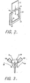
- Fig. 2 is a front elevation perspective view of a portion of a mask holder 22 as illustrated in Fig. 1.
- the mask holder 22 comprises a frame 25, and holder springs 26 made of stainless steel for example.
- the size of the mask holder is chosen as appropriate for the size of the mask.
- the mask 1 is inserted in the mask holder as shown by the arrow and supported by the holder springs 26.
- mask drying is achieved using a spin dryer or by means of natural drying; sometimes it is performed after water on the mask is replaced by alcohol.
- Fig. 3 shows schematically a known means for drying the mask by a jet of gas.
- the type of nozzle shown in Fig. 3 is sometimes called an air-knife nozzle.
- the nozzle 28 emits a knife shaped gas flow 29 diagonally onto the mask 1.
- the V shaped slit 27 provides a thin planar stream, the width of which is equal to the width of the mask.
- the gas flow from this type of nozzle spreads out as illustrated in Fig. 3, and it drags in the surrounding air as shown by broken line arrows 30. Because of the introduction into the gas flow of the surrounding air, surrounding contaminant is caught and the mask suffers contamination.
- the contaminant may include not only dust in the air, but also contamination which has been just removed from the mask. This spoils the cleaning effect of the washing apparatus.
- the jet nozzle is specially shaped. That is, it provides a pair of air-knife nozzles 7a and 7b, which emit gas jets onto the mask.
- Fig. 4(A) is a top view of means for emitting such gas jets and
- Fig. 4(B) is a sectional view along the line A-A of Fig. 4(A).
- Tips of nozzle bodies 31 a and 31 are cut aslant to the surface of the mask 1 at an angle of ⁇ (for example 50-60 degrees), and cover plates 32a and 32b are attached to the slanting cut parts of the tips, as shown in Fig. 4(B).
- An orifice 33a and an orifice 33b each with a width (thickness) W between the nozzle body and a cover plate is provided as shown in Fig. 4(A).
- an air-knife 34 (of nitrogen gas) is formed by the orifices 33a and 33b. The gas flow of the air-knife is directed downward along the surface of the mask 1.
- a gap d between the mask 1 and either of the cover plates 32a and 32b is set to be less than one mm.
- the nozzle bodies 31a and 31b are provided cavities 35a and 35b respectively, which are connected to gas pipes 36a and 36b respectively. The width of the resulting jet stream exceeds the width of the mask.
- micro air filters 13a and 13b close to the gas pipes 36a and 36b, which provide dust free air flows 37 towards the mask 1 Moreover, the gas in the airtight chamber 5 is evacuated by pumping from the bottom of the chamber (not shown). It will be apparent from the illustration that the problem of surrounding air being dragged into the knife- shaped air jet is completely prevented. Therefore, contamination by dragged-in air is eliminated.
- Fig. 5(A) illustrates schematically gas flow in the chamber when the washing apparatus is operating in the washing cycle (process)
- Fig. 5(B) illustrates schematically gas flow in the chamber when the washing apparatus is in the drying cycle (process).
- Reference numerals in the Figure designate corresponding parts of the apparatus to those shown in Fig. 1.
- the first shutter 2 is closed, outside air is taken in through the micro air filters 13a and 13b, and the pressure in the drying room is raised, so a stream of filtered air 39 flows into the washing room through a gap 38 between the separation wall 12 and the side wall of the chamber 5.
- filtered air flows through a gap 44 between the separation wall 12 and the second shutter II.
- the first shutter 2 is closed, but the second shutter 11 is open. Outside air is introduced through the micro air filters 13a and 13b, and the resulting filtered air stream 39 flows downward into the washing room 40.
- a pair of air-knives 34 blow gas downwards over the mask 1, so the mask is dried speedily.
- an automatic mask washing apparatus in accordance with the present invention, it is possible to clean a mask by processing in a chamber without the use of a strong oxidizing agent or strong alkaline agent. Damage to the mask caused by dust or mist is avoided, and clean surfaces of the mask are obtained; consequently, the reliability of the mask and the production yield of IC devices are increased.
Landscapes
- Physics & Mathematics (AREA)
- General Physics & Mathematics (AREA)
- Engineering & Computer Science (AREA)
- Mechanical Engineering (AREA)
- Preparing Plates And Mask In Photomechanical Process (AREA)
- Cleaning Or Drying Semiconductors (AREA)
- Cleaning By Liquid Or Steam (AREA)
- Exposure And Positioning Against Photoresist Photosensitive Materials (AREA)
- Cleaning In General (AREA)
- Details Or Accessories Of Spraying Plant Or Apparatus (AREA)
Applications Claiming Priority (2)
| Application Number | Priority Date | Filing Date | Title |
|---|---|---|---|
| JP122706/83 | 1983-07-06 | ||
| JP58122706A JPS6014244A (ja) | 1983-07-06 | 1983-07-06 | マスク洗浄装置 |
Publications (3)
| Publication Number | Publication Date |
|---|---|
| EP0131449A2 EP0131449A2 (en) | 1985-01-16 |
| EP0131449A3 EP0131449A3 (en) | 1988-01-13 |
| EP0131449B1 true EP0131449B1 (en) | 1990-05-09 |
Family
ID=14842589
Family Applications (1)
| Application Number | Title | Priority Date | Filing Date |
|---|---|---|---|
| EP84304632A Expired - Lifetime EP0131449B1 (en) | 1983-07-06 | 1984-07-06 | Automatic mask washing apparatus |
Country Status (5)
| Country | Link |
|---|---|
| US (1) | US4694527A (enExample) |
| EP (1) | EP0131449B1 (enExample) |
| JP (1) | JPS6014244A (enExample) |
| KR (1) | KR890002307B1 (enExample) |
| DE (1) | DE3482169D1 (enExample) |
Families Citing this family (55)
| Publication number | Priority date | Publication date | Assignee | Title |
|---|---|---|---|---|
| US4984597B1 (en) * | 1984-05-21 | 1999-10-26 | Cfmt Inc | Apparatus for rinsing and drying surfaces |
| JPH058675Y2 (enExample) * | 1985-03-13 | 1993-03-04 | ||
| US4924890A (en) * | 1986-05-16 | 1990-05-15 | Eastman Kodak Company | Method and apparatus for cleaning semiconductor wafers |
| US5221360A (en) * | 1987-04-27 | 1993-06-22 | Semitool, Inc. | Semiconductor processor methods |
| US5022419A (en) * | 1987-04-27 | 1991-06-11 | Semitool, Inc. | Rinser dryer system |
| US5095927A (en) * | 1987-04-27 | 1992-03-17 | Semitool, Inc. | Semiconductor processor gas-liquid separation |
| DE3733670C1 (de) * | 1987-10-05 | 1988-12-15 | Nukem Gmbh | Verfahren und Vorrichtung zum Reinigen insbesondere von scheibenfoermigen oxidischen Substraten |
| US4971083A (en) * | 1988-02-22 | 1990-11-20 | Austin American Technology | Apparatus and method for cleaning solder paste from items associated with surface mount technology manufacturing |
| US5158616A (en) * | 1988-07-22 | 1992-10-27 | Tokyo Electron Limited | Apparatus for cleaning a substrate |
| US5311891A (en) * | 1989-04-11 | 1994-05-17 | Japan Field Company, Ltd. | Solvent recovering system for a cleaning machine |
| US5148823A (en) * | 1990-10-16 | 1992-09-22 | Verteg, Inc. | Single chamber megasonic energy cleaner |
| US5275184A (en) * | 1990-10-19 | 1994-01-04 | Dainippon Screen Mfg. Co., Ltd. | Apparatus and system for treating surface of a wafer by dipping the same in a treatment solution and a gate device for chemical agent used in the apparatus and the system |
| US5186192A (en) * | 1990-12-14 | 1993-02-16 | Shin-Etsu Handotai Co., Ltd. | Apparatus for cleaning silicon wafer |
| US5203360A (en) * | 1990-12-17 | 1993-04-20 | Seagate Technology, Inc. | Disc washing system |
| JPH071796Y2 (ja) * | 1990-12-28 | 1995-01-18 | 大日本スクリーン製造株式会社 | 浸漬型基板処理装置 |
| JP3225441B2 (ja) * | 1991-04-23 | 2001-11-05 | 東京エレクトロン株式会社 | 処理装置 |
| KR0155390B1 (ko) * | 1991-05-08 | 1998-12-01 | 이노우에 아키라 | 세정 장치 |
| JPH04363022A (ja) * | 1991-06-06 | 1992-12-15 | Enya Syst:Kk | 貼付板洗浄装置 |
| JP2767165B2 (ja) * | 1991-07-31 | 1998-06-18 | 信越半導体株式会社 | ウエーハ洗浄槽 |
| ATE258084T1 (de) | 1991-10-04 | 2004-02-15 | Cfmt Inc | Superreinigung von komplizierten mikroteilchen |
| US5224503A (en) * | 1992-06-15 | 1993-07-06 | Semitool, Inc. | Centrifugal wafer carrier cleaning apparatus |
| US5379784A (en) * | 1993-01-23 | 1995-01-10 | Tokyo Electron Limited | Apparatus for cleaning conveyor chuck |
| US5608943A (en) * | 1993-08-23 | 1997-03-11 | Tokyo Electron Limited | Apparatus for removing process liquid |
| US5534076A (en) * | 1994-10-03 | 1996-07-09 | Verteg, Inc. | Megasonic cleaning system |
| US5772784A (en) * | 1994-11-14 | 1998-06-30 | Yieldup International | Ultra-low particle semiconductor cleaner |
| US5958146A (en) * | 1994-11-14 | 1999-09-28 | Yieldup International | Ultra-low particle semiconductor cleaner using heated fluids |
| DE19544677C2 (de) * | 1995-11-30 | 2000-04-27 | Leybold Ag | Verfahren zum Reinigen von scheibenförmigen Substraten |
| US5778554A (en) | 1996-07-15 | 1998-07-14 | Oliver Design, Inc. | Wafer spin dryer and method of drying a wafer |
| DE19639084A1 (de) * | 1996-09-24 | 1998-03-26 | Hans Henig | Vorrichtung und ein- oder mehrphasiges Verfahren zur Rückgewinnung ausgeschleppter Behandlungslösungen durch Tauchtrommeln |
| US6045624A (en) * | 1996-09-27 | 2000-04-04 | Tokyo Electron Limited | Apparatus for and method of cleaning objects to be processed |
| US6050275A (en) * | 1996-09-27 | 2000-04-18 | Tokyo Electron Limited | Apparatus for and method of cleaning objects to be processed |
| US6039059A (en) | 1996-09-30 | 2000-03-21 | Verteq, Inc. | Wafer cleaning system |
| US5806544A (en) * | 1997-02-11 | 1998-09-15 | Eco-Snow Systems, Inc. | Carbon dioxide jet spray disk cleaning system |
| KR100707107B1 (ko) * | 1997-07-17 | 2007-12-27 | 동경 엘렉트론 주식회사 | 세정.건조처리방법및장치 |
| US6395102B1 (en) * | 1997-08-25 | 2002-05-28 | Texas Instruments Incorporated | Method and apparatus for in-situ reticle cleaning at photolithography tool |
| TW405158B (en) * | 1997-09-17 | 2000-09-11 | Ebara Corp | Plating apparatus for semiconductor wafer processing |
| US6073640A (en) * | 1998-04-24 | 2000-06-13 | Valiant Machine & Tool Inc. | Part washer |
| US6062239A (en) * | 1998-06-30 | 2000-05-16 | Semitool, Inc. | Cross flow centrifugal processor |
| US6125863A (en) * | 1998-06-30 | 2000-10-03 | Semitool, Inc. | Offset rotor flat media processor |
| US6432214B2 (en) | 1998-07-10 | 2002-08-13 | Semitool, Inc. | Cleaning apparatus |
| US6516816B1 (en) * | 1999-04-08 | 2003-02-11 | Applied Materials, Inc. | Spin-rinse-dryer |
| US6305097B1 (en) * | 2000-06-29 | 2001-10-23 | Texas Instruments Incorporated | Apparatus for in-situ reticle cleaning at photolithography tool |
| US6725868B2 (en) * | 2000-11-14 | 2004-04-27 | Tokyo Electron Limited | Liquid processing apparatus |
| US6624060B2 (en) * | 2002-01-12 | 2003-09-23 | Taiwan Semiconductor Manufacturing Co., Ltd | Method and apparatus for pretreating a substrate prior to electroplating |
| JP2005534188A (ja) * | 2002-07-26 | 2005-11-10 | アプライド マテリアルズ インコーポレイテッド | スピンドライヤーの為の親水性構成要素 |
| US7127830B2 (en) * | 2004-08-02 | 2006-10-31 | Wafertech, Llc | Reticle carrier apparatus and method that tilts reticle for drying |
| KR100599947B1 (ko) * | 2004-12-30 | 2006-07-12 | 매그나칩 반도체 유한회사 | 노광장치 |
| JP4495700B2 (ja) * | 2006-07-14 | 2010-07-07 | 大日本印刷株式会社 | 機能性素子の製造方法およびその製造装置 |
| KR100953538B1 (ko) * | 2008-04-01 | 2010-04-21 | 삼성모바일디스플레이주식회사 | 스크린 마스크 세정 장치 |
| CN101961722B (zh) | 2009-07-24 | 2012-12-05 | 北京公科飞达交通工程发展有限公司 | 可与收、发卡机匹配的ic卡清洗机 |
| JP5440622B2 (ja) * | 2012-01-27 | 2014-03-12 | 株式会社リコー | 乾式クリーニング装置及び乾式クリーニング方法 |
| CN110026372A (zh) * | 2019-03-29 | 2019-07-19 | 云谷(固安)科技有限公司 | 一种掩模版清洗装置 |
| CN113819901B (zh) * | 2020-06-19 | 2023-11-07 | 长鑫存储技术有限公司 | 光学传感器的姿态调整装置及方法、自动物料运输系统 |
| CN114660902A (zh) * | 2020-12-23 | 2022-06-24 | 长鑫存储技术有限公司 | 曝光机 |
| CN112871831A (zh) * | 2020-12-31 | 2021-06-01 | 常州高光半导体材料有限公司 | 掩膜版除尘除油设备 |
Family Cites Families (22)
| Publication number | Priority date | Publication date | Assignee | Title |
|---|---|---|---|---|
| US3464428A (en) * | 1964-02-25 | 1969-09-02 | Robert W Kraeft | Machine for cleaning and drying table silver and control mechanism therefor |
| US3756898A (en) * | 1969-07-14 | 1973-09-04 | Buckbee Mears Co | Resistant system suitable for controlling etching without the aid of an etchant |
| US3636662A (en) * | 1969-12-10 | 1972-01-25 | Paul Donald Maca | Circuit board cleaning machine |
| US3691582A (en) * | 1970-07-30 | 1972-09-19 | Circuit Equipment Corp | Machine for cleaning printed circuit board |
| US4027686A (en) * | 1973-01-02 | 1977-06-07 | Texas Instruments Incorporated | Method and apparatus for cleaning the surface of a semiconductor slice with a liquid spray of de-ionized water |
| US3995343A (en) * | 1975-01-29 | 1976-12-07 | American Hoechst Corporation | Apparatus for processing a printing plate |
| JPS522076A (en) * | 1975-06-24 | 1977-01-08 | Koichi Iida | Apparatus for washing quenched plate |
| SU603703A1 (ru) * | 1976-06-14 | 1978-04-25 | Уральский научно-исследовательский институт трубной промышленности | Устройство дл химической обработки пакетов изделий |
| US4079522A (en) * | 1976-09-23 | 1978-03-21 | Rca Corporation | Apparatus and method for cleaning and drying semiconductors |
| DE2657558A1 (de) * | 1976-12-18 | 1978-06-22 | Basf Ag | Vorrichtung zum behandeln von druckplatten |
| JPS53136358A (en) * | 1977-05-02 | 1978-11-28 | Hitachi Ltd | Draft device with shutters for preventing interference between treating liquid |
| US4129919A (en) * | 1978-02-27 | 1978-12-19 | Lawrence R. Fitch | Printed circuit board scrubber and dryer |
| US4231806A (en) * | 1978-08-25 | 1980-11-04 | Caterpillar Tractor Co. | Fluid barrier means for parts washer apparatus |
| JPS5580335A (en) * | 1978-12-13 | 1980-06-17 | Mitsubishi Electric Corp | Manufacture of semiconductor device |
| US4268934A (en) * | 1979-09-12 | 1981-05-26 | Statics, Inc. | Cleaner for circuit boards |
| JPS56103440A (en) * | 1980-01-21 | 1981-08-18 | Mitsubishi Electric Corp | Apparatus for treating semiconductor substrate |
| US4296707A (en) * | 1980-02-13 | 1981-10-27 | Abex Corporation | Railroad car hand brake signal device |
| JPS5779619A (en) * | 1980-11-06 | 1982-05-18 | Fujitsu Ltd | Mask cleansing device |
| SU951017A1 (ru) * | 1980-11-19 | 1982-08-15 | Предприятие П/Я М-5273 | Камера дл проведени технологических операций в услови х высокой чистоты атмосферы |
| JPS587830A (ja) * | 1981-07-08 | 1983-01-17 | Hitachi Ltd | 薄片状物品の洗浄方法及び装置 |
| US4483040A (en) * | 1982-12-22 | 1984-11-20 | International Business Machines Corporation | In-line mask cleaning system |
| US4454003A (en) * | 1983-01-06 | 1984-06-12 | Systems Engineering & Manufacturing Corp. | Printed circuit board component conveyor apparatus and process |
-
1983
- 1983-07-06 JP JP58122706A patent/JPS6014244A/ja active Granted
-
1984
- 1984-06-26 KR KR1019840003605A patent/KR890002307B1/ko not_active Expired
- 1984-07-03 US US06/627,578 patent/US4694527A/en not_active Expired - Lifetime
- 1984-07-06 EP EP84304632A patent/EP0131449B1/en not_active Expired - Lifetime
- 1984-07-06 DE DE8484304632T patent/DE3482169D1/de not_active Expired - Lifetime
Also Published As
| Publication number | Publication date |
|---|---|
| KR850000783A (ko) | 1985-03-09 |
| KR890002307B1 (ko) | 1989-06-28 |
| JPS6014244A (ja) | 1985-01-24 |
| EP0131449A3 (en) | 1988-01-13 |
| JPS6235668B2 (enExample) | 1987-08-03 |
| US4694527A (en) | 1987-09-22 |
| EP0131449A2 (en) | 1985-01-16 |
| DE3482169D1 (en) | 1990-06-13 |
Similar Documents
| Publication | Publication Date | Title |
|---|---|---|
| EP0131449B1 (en) | Automatic mask washing apparatus | |
| JP3171807B2 (ja) | 洗浄装置及び洗浄方法 | |
| JP4056858B2 (ja) | 基板処理装置 | |
| JPS6347137B2 (enExample) | ||
| JP4404720B2 (ja) | 半導体基板の洗浄装置及び洗浄方法 | |
| JP3713447B2 (ja) | 現像処理装置 | |
| JP4579268B2 (ja) | 基板処理装置 | |
| KR100904278B1 (ko) | 기판처리장치 | |
| KR100753757B1 (ko) | 현상처리장치 및 현상처리방법 | |
| JP4628623B2 (ja) | ウェハ洗浄システムの処理前調整を実施する方法 | |
| JPH10154688A (ja) | 洗浄装置及び洗浄方法 | |
| JPH10247635A (ja) | ウェーハ等の洗浄処理装置及びその方法 | |
| TWI733060B (zh) | 濕式處理設備及其濕式處理方法 | |
| KR100375005B1 (ko) | 웨이퍼 클리닝 설비 및 이의 클리닝 방법 | |
| JP3453022B2 (ja) | 現像装置 | |
| US7415985B2 (en) | Substrate cleaning and drying apparatus | |
| JP2005101185A (ja) | 基板洗浄乾燥装置 | |
| JP6648248B2 (ja) | 基板処理方法 | |
| JP2005186028A (ja) | 角形基板の端縁部処理方法および装置 | |
| JP3810056B2 (ja) | 基板処理方法、現像処理方法および基板処理装置 | |
| JP4339299B2 (ja) | レジスト塗布装置 | |
| JP4194302B2 (ja) | 現像装置及び現像処理方法 | |
| JP4207205B2 (ja) | リフトオフ方法及び装置 | |
| KR100646060B1 (ko) | 현상방법 및 현상장치 | |
| KR200145644Y1 (ko) | 웨이퍼 이송벨트의 오염제거장치 |
Legal Events
| Date | Code | Title | Description |
|---|---|---|---|
| PUAI | Public reference made under article 153(3) epc to a published international application that has entered the european phase |
Free format text: ORIGINAL CODE: 0009012 |
|
| AK | Designated contracting states |
Designated state(s): DE FR GB |
|
| PUAL | Search report despatched |
Free format text: ORIGINAL CODE: 0009013 |
|
| AK | Designated contracting states |
Kind code of ref document: A3 Designated state(s): DE FR GB |
|
| 17P | Request for examination filed |
Effective date: 19880329 |
|
| 17Q | First examination report despatched |
Effective date: 19890227 |
|
| GRAA | (expected) grant |
Free format text: ORIGINAL CODE: 0009210 |
|
| AK | Designated contracting states |
Kind code of ref document: B1 Designated state(s): DE FR GB |
|
| REF | Corresponds to: |
Ref document number: 3482169 Country of ref document: DE Date of ref document: 19900613 |
|
| ET | Fr: translation filed | ||
| PLBE | No opposition filed within time limit |
Free format text: ORIGINAL CODE: 0009261 |
|
| STAA | Information on the status of an ep patent application or granted ep patent |
Free format text: STATUS: NO OPPOSITION FILED WITHIN TIME LIMIT |
|
| 26N | No opposition filed | ||
| PGFP | Annual fee paid to national office [announced via postgrant information from national office to epo] |
Ref country code: GB Payment date: 19920428 Year of fee payment: 9 |
|
| PGFP | Annual fee paid to national office [announced via postgrant information from national office to epo] |
Ref country code: FR Payment date: 19920730 Year of fee payment: 9 |
|
| PGFP | Annual fee paid to national office [announced via postgrant information from national office to epo] |
Ref country code: DE Payment date: 19920922 Year of fee payment: 9 |
|
| PG25 | Lapsed in a contracting state [announced via postgrant information from national office to epo] |
Ref country code: GB Effective date: 19930706 |
|
| GBPC | Gb: european patent ceased through non-payment of renewal fee |
Effective date: 19930706 |
|
| PG25 | Lapsed in a contracting state [announced via postgrant information from national office to epo] |
Ref country code: FR Effective date: 19940331 |
|
| PG25 | Lapsed in a contracting state [announced via postgrant information from national office to epo] |
Ref country code: DE Effective date: 19940401 |
|
| REG | Reference to a national code |
Ref country code: FR Ref legal event code: ST |