EP0123992B1 - Machine d'impression en creux - Google Patents
Machine d'impression en creux Download PDFInfo
- Publication number
- EP0123992B1 EP0123992B1 EP19840104227 EP84104227A EP0123992B1 EP 0123992 B1 EP0123992 B1 EP 0123992B1 EP 19840104227 EP19840104227 EP 19840104227 EP 84104227 A EP84104227 A EP 84104227A EP 0123992 B1 EP0123992 B1 EP 0123992B1
- Authority
- EP
- European Patent Office
- Prior art keywords
- cylinders
- printing machine
- impression
- central gear
- gear wheel
- Prior art date
- Legal status (The legal status is an assumption and is not a legal conclusion. Google has not performed a legal analysis and makes no representation as to the accuracy of the status listed.)
- Expired - Lifetime
Links
Images
Classifications
-
- B—PERFORMING OPERATIONS; TRANSPORTING
- B41—PRINTING; LINING MACHINES; TYPEWRITERS; STAMPS
- B41F—PRINTING MACHINES OR PRESSES
- B41F13/00—Common details of rotary presses or machines
-
- B—PERFORMING OPERATIONS; TRANSPORTING
- B41—PRINTING; LINING MACHINES; TYPEWRITERS; STAMPS
- B41F—PRINTING MACHINES OR PRESSES
- B41F9/00—Rotary intaglio printing presses
- B41F9/02—Rotary intaglio printing presses for multicolour printing
- B41F9/023—Web printing presses
- B41F9/028—Web printing presses of the satellite type
Definitions
- the invention relates to a gravure printing machine with several inking units and with several forme cylinders and impression cylinders, which are driven by a common central gear, in which the rolling circles of the gears of the impression cylinders are covered by the central gear in such a way that - in their axially parallel projection - they represent the pitch circle of the Touch the central gear from the inside.
- a printing machine of this type designed as a flexographic printing machine is shown in the unpublished DE-A-31 50 833.
- gravure printing machines are known from DE-A-2 262 550, which consist of a single stand, the individual printing units being arranged one above the other in the stand.
- Gravure printing machines of this type are often used for printing on textile webs, because in the case of textile webs in particular the printed color is immediately absorbed by the material, so that intermediate drying between the individual printing units is not necessary. Nevertheless, gravure printing machines of this type are built very high, so that accessibility and operability are extremely difficult. If such intaglio printing machines were to be used for printing on materials other than textile webs, drying blowers would still have to be used between the individual printing units, as a result of which the overall height would increase in such a way that the construction of such printing machines would no longer be possible.
- a gravure printing machine of the generic type is already known from US ⁇ A ⁇ 1 399 360, but has a relatively complicated structure with regard to the derivation of the drive of the forme cylinder and the impression cylinder from the central gear.
- the object of the invention is therefore to provide a simply constructed gravure printing machine with which even smaller jobs can be carried out economically.
- this object is achieved on the basis of a generic gravure printing machine by the characterizing features of patent claim 1. Accordingly, the carriages carrying the forme cylinders and the inking units can be moved on guides which are located radially outside the central gearwheel. Only this type of arrangement of the guides and carriages allows the gears of the forme cylinders to be brought into and out of engagement with the central gear by moving the carriages. Furthermore, the drive of the gears of the impression cylinders is derived from the central gear in that these gears are in engagement with the gears of the forme cylinders, which simultaneously mesh with the teeth of the central gear.
- the flexographic printing machine mentioned can be converted to a gravure printing machine in the manner according to the invention.
- the stands of gravure printing machines would have to be made extremely stable so that the high pressures occurring in gravure printing can be absorbed, tests have shown that the flexographic printing machine can be converted into a gravure printing machine in the manner according to the invention.
- the gravure printing machine according to the invention avoids the long web paths between the individual printing units, so that only a small amount of waste is produced during the printing.
- the gravure printing machine according to the invention is particularly suitable for printing on PVC webs, because only lower contact pressures are required for them.
- Drying blowers are expediently arranged between the individual printing units.
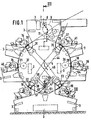
- FIG. 1 and 2 denote two side stands which are connected to one another via cross members 3 and via a central axis 4.
- the central axis 4 protrudes outwards from the stand 1, a central gear 6 being freely rotatably mounted on the projecting part 5.
- This central gear 6 receives its drive via the gear 7, the gear 8, the idler gear 9 and the drive gear 10 of the feed roller 11.
- two further feed rollers 12 and 13 are provided, the idler gear 9 with the drive wheel of the feed roller 13 also combs.
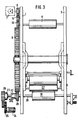
- All six forme cylinders 14 to 19 are driven by the central wheel 6, the drive for the forme cylinder 19 being evident from FIG. 3.
- This forme cylinder 19, like the other forme cylinders, is mounted between the stands 1 and 2, the forme cylinder axis 20 being passed through both stands 1 and. 2 protrudes externally by a certain amount.
- the axis part protruding from the stand 2 is connected to a cross register adjustment 21 which is known per se and which will not be described in more detail here.
- the part of the axis 20 which stands out to the left from the stand 1 with reference to FIG. 3 accommodates a longitudinal register adjustment 22 which is known per se and a coupling 23 with a fixed point circuit, so that on the one hand the forme cylinder 19 can be adjusted in the circumferential direction and on the other hand the Forme cylinder 19 can then be held in rotary motion via a continuous motor 24 and via the gearwheels 25 and 26 when the forme cylinder 19 is lifted off the impression cylinder 27 so that the ink does not dry out.
- the longitudinal register 22 as well as the function of the clutch 23 with fixed-point circuit should not be described in more detail here, because on the one hand they are not part of the invention and on the other hand represent a known prior art.
- the forme cylinder 19 is driven by the drive wheel 28, the pitch circle diameter of which corresponds to the diameter of the forme cylinder 19.
- a support press 33-38 is assigned to each impression roller 27-32.
- the two impressioners 28 and 31 and the support pressers 34 and 37 are rotatably supported in the two stands 1 and 2.
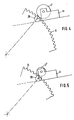
- the impression rollers 27 and 30 must be pivoted clockwise, to the same extent as the impression rollers 29 and 32 must be pivoted counterclockwise.
- four levers 42-45 are freely rotatably mounted on the central axis 4, two levers, namely the levers 42 and 43 and the levers 44 and 45, respectively, forming a pair of levers that oppose one another can be pivoted. So that each pair of levers lies as close as possible to the stand 1 or 2, the levers 42 and 44 are bent.
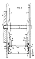
- the guides 46 and 47 are connected to the stands 1 and 2 and serve to guide screw nuts 48 and 49.
- the height of the latter can be adjusted via spindles 50 and 51.
- the lower ends of the spindles 50 and 51 have sprockets 52 and 53, which are parts of an angular gear, not shown.
- Both angular gears, not shown are connected to one another by a connecting shaft 54, so that both threaded nuts 48 and 49 can be raised or lowered by the same amount by turning the handwheel 55.
- the threaded nuts 48 and 49 have pins 56 and 57, which each carry two tabs 58 and 59 or 60 and 61.
- the free end of the tab 59 with the straight lever 45, the free end of the tab 58 with the cranked lever 44 is the free one End of the tab 61 with the straight lever 43 and the free end of the tab 61 with the cranked lever 42 articulated.
- the levers 44 and 45 or 42 and 43 can consequently be adjusted relative to one another by the same amount. This adjustment serves to be able to bring the impression rollers 27, 29, 30 and 32 into the correct position according to the forme cylinder used. 2, the impressioners and the support pressers are not shown. In Fig. 1, however, it is indicated that, for example, the impression 29 and the support press 35 are mounted at one end on one end of the lever 44.
- both the impression roller 29 and the support roller 35 are rotatably mounted at one end of the lever 42 (FIG. 2). From Fig. 2 it can still be seen that the two pins 56 and 57 are connected to one another via a rod 63 for stabilization purposes.
- Drying blowers 64 are provided between the individual printing units consisting of the forme cylinder, impression press and support press.
Landscapes
- Engineering & Computer Science (AREA)
- Mechanical Engineering (AREA)
- Rotary Presses (AREA)
Claims (3)
Applications Claiming Priority (2)
| Application Number | Priority Date | Filing Date | Title |
|---|---|---|---|
| DE3315890 | 1983-05-02 | ||
| DE19833315890 DE3315890C2 (de) | 1983-05-02 | 1983-05-02 | Tiefdruckmaschine |
Publications (3)
| Publication Number | Publication Date |
|---|---|
| EP0123992A2 EP0123992A2 (fr) | 1984-11-07 |
| EP0123992A3 EP0123992A3 (en) | 1986-11-20 |
| EP0123992B1 true EP0123992B1 (fr) | 1990-06-27 |
Family
ID=6197896
Family Applications (1)
| Application Number | Title | Priority Date | Filing Date |
|---|---|---|---|
| EP19840104227 Expired - Lifetime EP0123992B1 (fr) | 1983-05-02 | 1984-04-13 | Machine d'impression en creux |
Country Status (4)
| Country | Link |
|---|---|
| EP (1) | EP0123992B1 (fr) |
| JP (1) | JPS59209867A (fr) |
| DE (1) | DE3315890C2 (fr) |
| ES (1) | ES8501675A1 (fr) |
Families Citing this family (2)
| Publication number | Priority date | Publication date | Assignee | Title |
|---|---|---|---|---|
| DE19810708C2 (de) * | 1998-03-12 | 2002-06-27 | Martin Dreher | Einrichtung zum Drucken |
| DE102005003206A1 (de) * | 2005-01-24 | 2006-07-27 | Gallus Ferd. Rüesch AG | Tiefdruckwerk zum Bedrucken einer Bedruckstoffbahn in einer Druckmaschine |
Family Cites Families (5)
| Publication number | Priority date | Publication date | Assignee | Title |
|---|---|---|---|---|
| DE353363C (de) * | 1922-08-24 | Brinkmann Ernst | Mehrfarbentiefdruckmaschine | |
| US1399360A (en) * | 1919-04-19 | 1921-12-06 | Meisel Press Mfg Company | Printing-press |
| DE1636323A1 (de) * | 1968-03-15 | 1971-10-07 | Kleinewefers Soehne J | Foliendruckmaschine |
| IE39031B1 (en) * | 1972-12-21 | 1978-07-19 | Saueressig Gmbh | An intaglio printing machine for use with inks having a high solvent content |
| DE3150833C2 (de) * | 1981-12-22 | 1983-12-22 | Windmöller & Hölscher, 4540 Lengerich | Flexodruckmaschine |
-
1983
- 1983-05-02 DE DE19833315890 patent/DE3315890C2/de not_active Expired
-
1984
- 1984-04-13 EP EP19840104227 patent/EP0123992B1/fr not_active Expired - Lifetime
- 1984-04-30 ES ES532072A patent/ES8501675A1/es not_active Expired
- 1984-05-02 JP JP8915284A patent/JPS59209867A/ja active Pending
Also Published As
| Publication number | Publication date |
|---|---|
| ES532072A0 (es) | 1984-12-16 |
| DE3315890A1 (de) | 1984-11-08 |
| EP0123992A2 (fr) | 1984-11-07 |
| ES8501675A1 (es) | 1984-12-16 |
| JPS59209867A (ja) | 1984-11-28 |
| EP0123992A3 (en) | 1986-11-20 |
| DE3315890C2 (de) | 1986-03-27 |
Similar Documents
| Publication | Publication Date | Title |
|---|---|---|
| EP0352599B1 (fr) | Rotative à bobine pour l'impression continue sans utilisation d'un canal de serrage | |
| EP0465789B1 (fr) | Unité d'impression avec des moyens pour remplacer la plaque d'impression à la volée | |
| DE2951249A1 (de) | Antrieb fuer rollenrotations- offsetdruckmaschinen | |
| EP0185965A2 (fr) | Cylindre de transfert pour machine à imprimer des feuilles | |
| CH618384A5 (fr) | ||
| DE2243054C3 (de) | Rundstrickmaschine | |
| DE3315891C2 (de) | Druckmaschine | |
| CH654250A5 (de) | Drehrichtungsvariabler antrieb fuer eine rollen-rotationsdruckmaschine mit einem zehnzylinder-druckwerk. | |
| EP0019697B1 (fr) | Dispositif de réglage du repérage latéral et circonférentiel sur les machines à imprimer rotatives | |
| DE2458772B2 (de) | Rollen-Rotations-Druckmaschine mit einem Farbwerk, das zwei voneinander trennbare Antriebe aufweist | |
| EP0123992B1 (fr) | Machine d'impression en creux | |
| DE645820C (de) | Mit einem Anilinfarbwerk arbeitende Rotationsdruckmaschine | |
| DE2336734C3 (de) | Vorrichtung zum beidseitigen Antrieb einer Rundschablone jnit einer Walzenrakel in einer Druckmaschine für Warenbahnen | |
| DE4038510A1 (de) | Registerstellvorrichtung | |
| DE494413C (de) | Maschine zum Bedrucken von Papier- und Stoffbahnen | |
| DE2143402A1 (de) | Vorrichtung zum Verschieben des Siebes einer Siebdruckmaschine | |
| DE2553768B2 (de) | Rollen-Rotationsdruckmaschine | |
| DE2724531B1 (de) | Vorrichtung zum An- und Abstellen eines Druckwerks einer Druckmaschine | |
| DE424947C (de) | Walzendruckmaschine fuer festen oder losen Rapport | |
| DE144033C (fr) | ||
| DE3037723A1 (de) | Bogenuebergabeeinrichtung einer druckmaschine | |
| DE2607929C3 (de) | Siebdruckmaschine mit mindestens zwei Druckwerken | |
| DE553269C (de) | Vorrichtung zur Veraenderung der Druckbreite bei Walzendruckmaschinen | |
| DE3934067C2 (de) | Farbwerk einer Druckmaschine mit einer changierenden Auftragwalze | |
| DE2343102C3 (de) | Rotations-Druckmaschine für indirekten Druck |
Legal Events
| Date | Code | Title | Description |
|---|---|---|---|
| PUAI | Public reference made under article 153(3) epc to a published international application that has entered the european phase |
Free format text: ORIGINAL CODE: 0009012 |
|
| AK | Designated contracting states |
Designated state(s): BE CH FR GB IT LI |
|
| PUAL | Search report despatched |
Free format text: ORIGINAL CODE: 0009013 |
|
| AK | Designated contracting states |
Kind code of ref document: A3 Designated state(s): BE CH FR GB IT LI |
|
| 17P | Request for examination filed |
Effective date: 19870213 |
|
| 17Q | First examination report despatched |
Effective date: 19880531 |
|
| GRAA | (expected) grant |
Free format text: ORIGINAL CODE: 0009210 |
|
| AK | Designated contracting states |
Kind code of ref document: B1 Designated state(s): BE CH FR GB IT LI |
|
| GBT | Gb: translation of ep patent filed (gb section 77(6)(a)/1977) | ||
| ET | Fr: translation filed | ||
| ITF | It: translation for a ep patent filed |
Owner name: BUGNION S.P.A. |
|
| PG25 | Lapsed in a contracting state [announced via postgrant information from national office to epo] |
Ref country code: GB Effective date: 19910413 |
|
| PLBE | No opposition filed within time limit |
Free format text: ORIGINAL CODE: 0009261 |
|
| STAA | Information on the status of an ep patent application or granted ep patent |
Free format text: STATUS: NO OPPOSITION FILED WITHIN TIME LIMIT |
|
| PG25 | Lapsed in a contracting state [announced via postgrant information from national office to epo] |
Ref country code: CH Effective date: 19910430 Ref country code: LI Effective date: 19910430 Ref country code: BE Effective date: 19910430 |
|
| 26N | No opposition filed | ||
| BERE | Be: lapsed |
Owner name: WINDMOLLER & HOLSCHER Effective date: 19910430 |
|
| GBPC | Gb: european patent ceased through non-payment of renewal fee | ||
| PG25 | Lapsed in a contracting state [announced via postgrant information from national office to epo] |
Ref country code: FR Effective date: 19911230 |
|
| REG | Reference to a national code |
Ref country code: CH Ref legal event code: PL |
|
| REG | Reference to a national code |
Ref country code: FR Ref legal event code: ST |