EP0114919A1 - Druckkontakt - Google Patents
Druckkontakt Download PDFInfo
- Publication number
- EP0114919A1 EP0114919A1 EP83104842A EP83104842A EP0114919A1 EP 0114919 A1 EP0114919 A1 EP 0114919A1 EP 83104842 A EP83104842 A EP 83104842A EP 83104842 A EP83104842 A EP 83104842A EP 0114919 A1 EP0114919 A1 EP 0114919A1
- Authority
- EP
- European Patent Office
- Prior art keywords
- contact
- contact pin
- pressure
- guide part
- tight
- Prior art date
- Legal status (The legal status is an assumption and is not a legal conclusion. Google has not performed a legal analysis and makes no representation as to the accuracy of the status listed.)
- Granted
Links
- 238000007789 sealing Methods 0.000 claims abstract description 7
- 239000013013 elastic material Substances 0.000 claims abstract description 5
- 239000011324 bead Substances 0.000 claims description 5
- 239000000463 material Substances 0.000 claims description 2
- 230000000284 resting effect Effects 0.000 claims description 2
- 239000004020 conductor Substances 0.000 description 2
- 239000002826 coolant Substances 0.000 description 2
- 239000007788 liquid Substances 0.000 description 2
- 239000002184 metal Substances 0.000 description 2
- 238000005299 abrasion Methods 0.000 description 1
- 230000005540 biological transmission Effects 0.000 description 1
- 230000006835 compression Effects 0.000 description 1
- 238000007906 compression Methods 0.000 description 1
- 238000000748 compression moulding Methods 0.000 description 1
- 230000000875 corresponding effect Effects 0.000 description 1
- 230000007423 decrease Effects 0.000 description 1
- 238000006073 displacement reaction Methods 0.000 description 1
- 229920001971 elastomer Polymers 0.000 description 1
- 238000010292 electrical insulation Methods 0.000 description 1
- 238000007373 indentation Methods 0.000 description 1
- 230000007774 longterm Effects 0.000 description 1
- 239000000314 lubricant Substances 0.000 description 1
- 238000000034 method Methods 0.000 description 1
- 238000000465 moulding Methods 0.000 description 1
- 239000012811 non-conductive material Substances 0.000 description 1
- 229920002635 polyurethane Polymers 0.000 description 1
- 239000004814 polyurethane Substances 0.000 description 1
- 230000000717 retained effect Effects 0.000 description 1
- 239000000126 substance Substances 0.000 description 1
- 229920003002 synthetic resin Polymers 0.000 description 1
- 239000000057 synthetic resin Substances 0.000 description 1
Images

Classifications
-
- H—ELECTRICITY
- H01—ELECTRIC ELEMENTS
- H01R—ELECTRICALLY-CONDUCTIVE CONNECTIONS; STRUCTURAL ASSOCIATIONS OF A PLURALITY OF MUTUALLY-INSULATED ELECTRICAL CONNECTING ELEMENTS; COUPLING DEVICES; CURRENT COLLECTORS
- H01R13/00—Details of coupling devices of the kinds covered by groups H01R12/70 or H01R24/00 - H01R33/00
- H01R13/02—Contact members
- H01R13/22—Contacts for co-operating by abutting
- H01R13/24—Contacts for co-operating by abutting resilient; resiliently-mounted
- H01R13/2464—Contacts for co-operating by abutting resilient; resiliently-mounted characterized by the contact point
- H01R13/2471—Contacts for co-operating by abutting resilient; resiliently-mounted characterized by the contact point pin shaped
Definitions
- the invention relates to a pressure contact, consisting of two coaxially assigned and liquid-tight and electrically insulated contact pins mounted in sockets, of which at least one is axially movably mounted on a spring body in order to obtain a uniform contact pressure in the assembled state.
- Pressure contacts of the type specified above are required in order to transmit electrical signals from sensors in machine elements, the sensors being inserted and clamped manually or automatically into a clamping unit of a processing machine.
- the space available is extremely limited and it is therefore difficult to ensure good electrical insulation in the long term, particularly with regard to the more or less continuous exposure to metal chips and / or liquid coolants.
- the invention has for its object to show a cost-effective pressure contact of small size for the application area mentioned, which ensures reliable transmission of electrical signals while avoiding short-circuiting.
- a pressure contact of the type mentioned at the beginning in which the spring body and the socket are formed by a liquid-tight and electrically insulated tube which surrounds the contact pin on all sides and is made of an elastic material and which has at least one inwardly projecting step which Grips contact pin in an undercut adapted profile and a sealing lip enclosing the contact surface, sealingly resting on the opposite socket under an elastic bias.
- the hose can be provided with a centrally arranged guide part as well as with a step which is arranged on a projection projecting beyond the guide part in the axial direction.
- the step is expediently followed by a radial direction. protruding bulge formed inside.
- the hose can consist of several individual parts that are glued or clamped together. On the other hand, it has proven advantageous to produce the hose monolithically from a single block of material and to give it its final shape in the course of a compression molding process. In addition to rubber with a Shore A hardness of around 65-90, the use of elastomeric polyurethane has proven particularly effective because of its higher abrasion resistance.
- the hose 1 according to FIG. 1 consists of a rubber-elastic material with a Shore A hardness of 60. This is divided in the axial direction into the gripping lip part 5, the guide part 2 and the projection 3.
- the gripping lip part 5 serves to axially fix the contact pin provided with a mushroom-shaped head. This is enclosed on the end face by the sealing lip 6, so that liquid cannot penetrate into the space between the hose and the contact pin in the event of accidental loading.
- the guide part 2 ensures a coaxial assignment of the received contact pin to the receiving housing bore. This assignment is always retained even when the contact pin is axially displaced.
- the guide part 2 is provided with a bead 7 projecting outwards in the radial direction, which bead serves to axially fix it in the receiving housing bore.
- the projection 3 projecting over the guide part in the axial direction has a comparatively substantially reduced wall thickness and an inwardly projecting bead 4. Via the latter, the forces introduced when the contact pin to be received is pressed in are transmitted to the projection 3, which is thereby elastically stretched, and one Resetting of the contact pin when the indentation force decreases.
- the released spring force is essentially constant, which ensures constant contact pressure of the contact surface of the contact pin on the associated contact surface of the opposite contact pin while avoiding overloads.
- Figure 2 makes reference to the pressure contact and the connection to the coaxial compression of the contact surfaces of the contact pins.
- These consist of a conductive material, preferably of metal, and are mounted in a liquid-tight socket made of a non-conductive material. They carry a terminal contact for the connection of an electrical conductor, for example a cable, at the rear end.
- the socket of the upper contact pin consists of a molding made of synthetic resin. It ends together with the receiving housing part and the contact surface of the upper contact pin in a common plane.
- the lower contact pin is mounted in a liquid-impermeable hose made of an elastic material. It has a hemispherical contact surface 9, which extends beyond the end face 8 of the receiving housing part in the axial direction before the assembly, as does the sealing lip 5 surrounding the contact surface.
- the axial fixation of the tube piece, based on the receiving housing part, takes place through the circumferential bead 7. This engages in an assigned groove of the receiving housing part, which has a congruent profile.
- two stages 10, 11 are provided which engage in correspondingly formed undercuts of the contact pin.
Landscapes
- Connector Housings Or Holding Contact Members (AREA)
- Secondary Cells (AREA)
- Measuring Fluid Pressure (AREA)
Abstract
Description
- Die Erfindung betrifft einen Druckkontakt, bestehend aus zwei einander koaxial zugeordneten und in Buchsen flüssigkeitsdicht und elektrisch isoliert gelagerten Kontaktstiften, von denen wenigstens der eine axial beweglich auf einem Federkörper gelagert ist, um eine gleichmäßige Anpressung der Kontaktflächen in zusammengefügtem Zustand zu erhalten.
- Druckkontakte der vorstehend angegebenen Art werden benötigt, um elektrische Signale von Meßfühlern in Maschinenelementen zu übertragen, wobei die Meßfühler manuell oder automatisch in eine Spanneinheit einer Bearbeitungsmaschine eingeführt und gespannt werden. Der zur Verfügung stehende Raum ist außerordentlich begrenzt, und es ist dadurch schwierig, langfristig eine gute elektrische Isolierung sicherzustellen, insbesondere im Hinblick auf die mehr oder weniger kontinuierliche Beaufschlagung mit metallischen Spänen und/oder durch flüssige Kühlmittel.
- Der Erfindung liegt die Aufgabe zugrunde, einen kostengünstig herstellbaren Druckkontakt geringer Baugröße für das angesprochene Anwendungsgebiet zu zeigen, der unter Vermeidung von Kurzschlußbildungen eine zuverlässige Übertragung elektrischer Signale gewährleistet.
- Diese Aufgabe wird erfindungsgemäß durch einen Druckkontakt der eingangs genannten Art gelöst, bei dem der Federkörper und die Buchse durch einen den Kontaktstift allseitig umschließenden, flüssigkeitsdichten und elektrisch isolierten Schlauch aus einem elastischen Werkstoff gebildet wird, der wenigstens eine nach innen vorspringende Stufe aufweist, die den Kontaktstift in einer Hinterschneidung angepaßten Profils umgreift sowie eine die Kontaktfläche umschließende, unter einer elastischen Vorspannung dichtend an der gegenüberliegenden Buchse anliegende Dichtlippe.
- Der Schlauch kann mit einem zentral angeordneten Führungsteil versehen sein sowie mit einer Stufe, die an einem den Führungsteil in axialer Richtung überragenden Vorsprung angeordnet ist. Die Stufe wird in diesem Falle zweckmäßigerweise durch einen in radialer Richtung nach . innen vorspringenden Wulst gebildet.
- Der Schlauch kann aus mehreren Einzelteilen bestehen, die untereinander verklebt oder verklammert sind. Als vorteilhafter hat es sich hingegen bewährt, den Schlauch monolithisch aus einem einzigen Werkstoffblock herzustellen, und diesem seine endgültige Gestalt im Zuge eines Formpreßverfahrens zu verleihen. Neben Gummi einer Härte Shore A von etwa 65 - 90 hat sich insbesondere die Verwendung elastomeren Polyurethans wegen seiner höheren Abriebbeständigkeit ausgezeichnet bewährt.
- Eine beispielhafte Ausführung des erfindungsgemäß vorgeschlagenen Druckkontaktes wird nachfolgend anhand der in der Anlage beigefügten Zeichnung näher erläutert.
- Es zeigen:
- Figur 1 den zur Anwendung kommenden Schlauch in längsgeschnittener Darstellung.
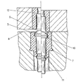
- Figur 2 den Schlauch gemäß Figur 1 in eingebauter Form in einem Druckkontakt, der im linken Teil der Darstellung geöffnet, im rechten Teil der Darstellung hingegen geschlossen ist.
- Der Schlauch 1 gemäß Figur 1 besteht aus einem gummielastischen Werkstoff mit einer Härte Shore A von 60 . Dieser ist in axialer Richtung gegliedert in den Greiflippenteil 5, den Führungsteil 2 und den Vorsprung 3.
- Der Greiflippenteil 5 dient der axialen Festlegung des mit einem pilzförmigen Kopf versehenen Kontaktstiftes. Dieser wird stirnseitig von der Dichtlippe 6 umschlossen, wodurch Flüssigkeit bei einer versehentlichen Beaufschlagung nicht in den Zwischenraum zwischen dem Schlauch und dem Kontaktstift eindringen kann.
- Der Führungsteil 2 gewährleistet eine koaxiale Zuordnung des aufgenommenen Kontaktstiftes zu der aufnehmenden Gehäusebohrung. Diese Zuordnung bleibt auch bei einer axialen Verlagerung des Kontaktstiftes stets erhalten. Im rückwärtigen Bereich ist der Führungsteil 2 mit einem in radialer Richtung nach außen vorspringenden Wulst 7 versehen, der seiner axialen F-estlegung in der aufnehmenden Gehäusebohrung dient.
- Der den Führungsteil in axialer Richtung überragende Vorsprung 3 weist eine vergleichsweise wesentlich verminderte Wandstärke auf sowie einen nach innen vorspringenden Wulst 4. Über letzteren werden die bei einer Eindrückung des aufzunehmenden Kontaktstiftes eingeleiteten Kräfte auf den Vorsprung 3 übertragen, der dadurch elastisch gedehnt wird, und eine Rückstellung des Kontaktstiftes bei nachlassender Eindrückkraft bewirkt. Die freigesetzte Federkraft ist im wesentlichen konstant, wodurch unter Vermeidung von Überlastungen eine gleichbleibende Anpressung der Kontaktfläche des Kontaktstiftes an die zugehörige Kontaktfläche des gegenüberliegenden Kontaktstiftes gewährleistet wird.
- Figur 2 nimmt Bezug auf den Druckkontakt vor und dem Anschluß an die koaxiale Zusammenpressung der Kontaktflächen der Kontaktstifte. Diese bestehen aus einem leitenden Werkstoff, vorzugsweise aus Metall, und sind in einer flüssigkeitsdichten Buchse aus einem nicht leitenden Werkstoff gelagert. Sie tragen am rückwärtigen Ende einen Klemmkontakt für den Anschluß eines elektrischen Leiters, beispielsweise eines Kabels.
- Die Buchse des oberen Kontaktstiftes besteht aus einem Preßkörper aus Kunstharz. Sie endet zusammen mit dem aufnehmenden Gehäuseteil und der Kontaktfläche des oberen Kontaktstiftes in einer gemeinsamen Ebene.
- Der untere Kontaktstift ist im Gegensatz zu dem oberen in einem flüssigkeitsundurchlässigen Schlauch aus einem elastischen Werkstoff gelagert. Er weist eine halbkugelig ausgebildete Kontaktfläche 9 auf, die die Stirnfläche 8 des aufnehmenden Gehäuseteiles vor dem Zusammenfügen in axialer Richtung ebenso überragt wie die die Kontaktfläche umschließende Dichtlippe 5.
- Die axiale Festlegung des Schlauchstückes, bezogen auf das aufnehmende Gehäuseteil, erfolgt durch den umlaufenden Wulst 7. Dieser greift in eine zugeordnete Nute des aufnehmenden Gehäuseteiles ein, die ein deckungsgleiches Profil aufweist.
- Für die axiale Festlegung des Kontaktstiftes,bezogen auf den Schlauch, sind zwei Stufen 10, 11 vorgesehen, die in entsprechend ausgebildete Hinterschneidungen des Kontaktstiftes eingreifen.
- Bei einer koaxialen Zusammenpressung der Kontaktflächen der Kontaktstifte ergibt sich eine Rückwärtsverlagerung des unteren von beiden, bis die beiderseitigen Stirnflächen der aufnehmenden Gehäuseteile einander berühren. Die Kontaktflächen werden in dieser Situation federnd gegeneinander gepreßt, wodurch ein ausreichender elektrischer Kontakt sichergestellt ist. Zugleich ergibt sich eine elastische Anpressung der Dichtlippe 5 gegen die Stirnfläche der Buchse 12, wodurch die elektrisch leitende Verbindung zwischen den Kontaktflächen der Einwirkung äußerer Stoffe entzogen ist, insbesondere der Einwirkung von Kühl- und Schmiermitteln. Eine entsprechende Wirkung läßt sich selbstverständlich auch dann erzielen, wenn beide Kontaktstifte in einem Schlauch gemäß Figur 1 gelagert und in axialer Richtung federnd abgestützt sind.
Claims (4)
Priority Applications (1)
| Application Number | Priority Date | Filing Date | Title |
|---|---|---|---|
| AT83104842T ATE19163T1 (de) | 1982-12-28 | 1983-05-17 | Druckkontakt. |
Applications Claiming Priority (2)
| Application Number | Priority Date | Filing Date | Title |
|---|---|---|---|
| DE3248336 | 1982-12-28 | ||
| DE3248336A DE3248336C1 (de) | 1982-12-28 | 1982-12-28 | Druckkontakt |
Publications (2)
| Publication Number | Publication Date |
|---|---|
| EP0114919A1 true EP0114919A1 (de) | 1984-08-08 |
| EP0114919B1 EP0114919B1 (de) | 1986-04-09 |
Family
ID=6181977
Family Applications (1)
| Application Number | Title | Priority Date | Filing Date |
|---|---|---|---|
| EP83104842A Expired EP0114919B1 (de) | 1982-12-28 | 1983-05-17 | Druckkontakt |
Country Status (3)
| Country | Link |
|---|---|
| EP (1) | EP0114919B1 (de) |
| AT (1) | ATE19163T1 (de) |
| DE (2) | DE3248336C1 (de) |
Cited By (2)
| Publication number | Priority date | Publication date | Assignee | Title |
|---|---|---|---|---|
| FR2812459A1 (fr) * | 2000-07-25 | 2002-02-01 | Thomson Csf | Fiche de connecteur et son procede de fabrication |
| WO2020212338A1 (de) * | 2019-04-15 | 2020-10-22 | Cinogy Gmbh | Behandlungsanordnung für die behandlung einer oberfläche eines körpers mit einem dielektrisch behinderten plasma |
Families Citing this family (1)
| Publication number | Priority date | Publication date | Assignee | Title |
|---|---|---|---|---|
| DE102012215954A1 (de) * | 2012-09-10 | 2014-03-13 | Tyco Electronics Amp Gmbh | Elektrische Kontaktvorrichtung, insbesondere Steckverbinder |
Citations (4)
| Publication number | Priority date | Publication date | Assignee | Title |
|---|---|---|---|---|
| FR1185592A (fr) * | 1956-11-05 | 1959-08-03 | Plessey Co Ltd | Connecteur à contact par aboutement |
| GB975395A (en) * | 1959-10-13 | 1964-11-18 | Secr Aviation | Improvements in or relating to electrical connectors |
| DE2048578A1 (de) * | 1969-10-08 | 1971-04-22 | Inst Francais Du Petrol | Dichte elektrische Kupplungsver bindung |
| DE2914658A1 (de) * | 1978-04-17 | 1979-10-18 | Ford Werke Ag | Trennbare, elektrische kontaktvorrichtung, insbesondere zwischen gegeneinander bewegbaren karosseriebauteilen |
Family Cites Families (2)
| Publication number | Priority date | Publication date | Assignee | Title |
|---|---|---|---|---|
| DE1730714U (de) * | 1954-10-11 | 1956-09-27 | Siemens Ag | Einrichtung zum abdichten von in einer wanddurchbrechung angeordneten betaetigungsdruckknoepfen. |
| DE1798766U (de) * | 1958-03-21 | 1959-10-29 | Calor Emag Elektrizitaets Ag | Druckkontaktanordnung. |
-
1982
- 1982-12-28 DE DE3248336A patent/DE3248336C1/de not_active Expired
-
1983
- 1983-05-17 DE DE8383104842T patent/DE3362886D1/de not_active Expired
- 1983-05-17 EP EP83104842A patent/EP0114919B1/de not_active Expired
- 1983-05-17 AT AT83104842T patent/ATE19163T1/de not_active IP Right Cessation
Patent Citations (4)
| Publication number | Priority date | Publication date | Assignee | Title |
|---|---|---|---|---|
| FR1185592A (fr) * | 1956-11-05 | 1959-08-03 | Plessey Co Ltd | Connecteur à contact par aboutement |
| GB975395A (en) * | 1959-10-13 | 1964-11-18 | Secr Aviation | Improvements in or relating to electrical connectors |
| DE2048578A1 (de) * | 1969-10-08 | 1971-04-22 | Inst Francais Du Petrol | Dichte elektrische Kupplungsver bindung |
| DE2914658A1 (de) * | 1978-04-17 | 1979-10-18 | Ford Werke Ag | Trennbare, elektrische kontaktvorrichtung, insbesondere zwischen gegeneinander bewegbaren karosseriebauteilen |
Cited By (3)
| Publication number | Priority date | Publication date | Assignee | Title |
|---|---|---|---|---|
| FR2812459A1 (fr) * | 2000-07-25 | 2002-02-01 | Thomson Csf | Fiche de connecteur et son procede de fabrication |
| WO2020212338A1 (de) * | 2019-04-15 | 2020-10-22 | Cinogy Gmbh | Behandlungsanordnung für die behandlung einer oberfläche eines körpers mit einem dielektrisch behinderten plasma |
| US12418974B2 (en) | 2019-04-15 | 2025-09-16 | Cinogy Gmbh | Treatment assembly for treating the surface of a body with a dielectrically limited plasma |
Also Published As
| Publication number | Publication date |
|---|---|
| DE3248336C1 (de) | 1984-07-05 |
| ATE19163T1 (de) | 1986-04-15 |
| EP0114919B1 (de) | 1986-04-09 |
| DE3362886D1 (en) | 1986-05-15 |
Similar Documents
| Publication | Publication Date | Title |
|---|---|---|
| DE2522499C2 (de) | Elektrischer Steckverbinder | |
| DE2923399C2 (de) | Verfahren zur elektrischen Verbindung eines Koaxialkabels und Anschlußarmatur für Koaxialkabel | |
| DE60110015T2 (de) | Dichtungsring | |
| DE69408931T2 (de) | Kabelklemmvorrichtung für wasserdichten Verbinder | |
| DE19953663A1 (de) | Anschlußklemme | |
| DE69009564T2 (de) | Bioelektrische Elektrode mit Anschlussvorrichtung. | |
| DE19755530C2 (de) | Einrichtung zur Zugentlastung elektrischer oder optischer Kabel | |
| DE69300593T2 (de) | Gummidichtung für wasserdichten Steckverbinder. | |
| EP1355386A1 (de) | Rundsteckverbinder für abgeschirmte elektrische Kabel | |
| DE10111474B4 (de) | Verbinder-Abdichtanordnung | |
| DE69501803T2 (de) | Wasserfeste Dichtung für Verbinder | |
| DE2625648A1 (de) | Kontaktstecker und steckverbindung aus kontaktstecker und kontaktbuchse | |
| EP0233319A2 (de) | Koaxialer Winkelstecker | |
| DE3318248A1 (de) | Mehrpoliger elektrischer stecker, insbesondere rundstecker | |
| DE19822015A1 (de) | Abgeschirmter Stecker für eine direkte Verbindung mit einem Gerät | |
| DE69424682T2 (de) | Überbrückungssteckverbinder | |
| DE69513607T2 (de) | Isoliertes anschlusselement mit zwei integrierten, aufgeweiteten enden der buchse | |
| DE102018211218B4 (de) | Anschlussverbindungsstruktur und Buchsenanschluss | |
| EP0134542A1 (de) | Steckverbinder zum lösbaren Anschluss von Kabelleitungen | |
| DE69915738T2 (de) | Positiv verriegelter Steckverbinder | |
| DE3110660A1 (de) | Garnitur fuer das ende eines mittelspannnungs- oder hochspannunskabels | |
| EP0114919B1 (de) | Druckkontakt | |
| EP0044387A1 (de) | Universalsteckergehäuse für ein löt-, schraub- und abisolierfreies System zum Prüfen, Verbinden und Trennen von Leitungszügen | |
| DE3406739A1 (de) | Elektrischer steckverbinder | |
| DE2550939A1 (de) | Zugentlastung fuer anschlusskabel von elektrogeraeten |
Legal Events
| Date | Code | Title | Description |
|---|---|---|---|
| PUAI | Public reference made under article 153(3) epc to a published international application that has entered the european phase |
Free format text: ORIGINAL CODE: 0009012 |
|
| AK | Designated contracting states |
Designated state(s): AT DE FR GB IT SE |
|
| 17P | Request for examination filed |
Effective date: 19840608 |
|
| GRAA | (expected) grant |
Free format text: ORIGINAL CODE: 0009210 |
|
| ITF | It: translation for a ep patent filed | ||
| AK | Designated contracting states |
Kind code of ref document: B1 Designated state(s): AT DE FR GB IT SE |
|
| REF | Corresponds to: |
Ref document number: 19163 Country of ref document: AT Date of ref document: 19860415 Kind code of ref document: T |
|
| REF | Corresponds to: |
Ref document number: 3362886 Country of ref document: DE Date of ref document: 19860515 |
|
| ET | Fr: translation filed | ||
| PLBE | No opposition filed within time limit |
Free format text: ORIGINAL CODE: 0009261 |
|
| STAA | Information on the status of an ep patent application or granted ep patent |
Free format text: STATUS: NO OPPOSITION FILED WITHIN TIME LIMIT |
|
| 26N | No opposition filed | ||
| ITTA | It: last paid annual fee | ||
| EAL | Se: european patent in force in sweden |
Ref document number: 83104842.6 |
|
| REG | Reference to a national code |
Ref country code: GB Ref legal event code: IF02 |
|
| PGFP | Annual fee paid to national office [announced via postgrant information from national office to epo] |
Ref country code: DE Payment date: 20020418 Year of fee payment: 20 |
|
| PGFP | Annual fee paid to national office [announced via postgrant information from national office to epo] |
Ref country code: GB Payment date: 20020425 Year of fee payment: 20 |
|
| PGFP | Annual fee paid to national office [announced via postgrant information from national office to epo] |
Ref country code: AT Payment date: 20020522 Year of fee payment: 20 |
|
| PGFP | Annual fee paid to national office [announced via postgrant information from national office to epo] |
Ref country code: FR Payment date: 20020523 Year of fee payment: 20 |
|
| PGFP | Annual fee paid to national office [announced via postgrant information from national office to epo] |
Ref country code: SE Payment date: 20020524 Year of fee payment: 20 |
|
| PG25 | Lapsed in a contracting state [announced via postgrant information from national office to epo] |
Ref country code: GB Free format text: LAPSE BECAUSE OF EXPIRATION OF PROTECTION Effective date: 20030516 |
|
| PG25 | Lapsed in a contracting state [announced via postgrant information from national office to epo] |
Ref country code: AT Free format text: LAPSE BECAUSE OF EXPIRATION OF PROTECTION Effective date: 20030517 |
|
| REG | Reference to a national code |
Ref country code: GB Ref legal event code: PE20 |
|
| EUG | Se: european patent has lapsed |