EP0103412B1 - Appareil de contrôle pour des convertisseurs et analogues - Google Patents
Appareil de contrôle pour des convertisseurs et analogues Download PDFInfo
- Publication number
- EP0103412B1 EP0103412B1 EP83304679A EP83304679A EP0103412B1 EP 0103412 B1 EP0103412 B1 EP 0103412B1 EP 83304679 A EP83304679 A EP 83304679A EP 83304679 A EP83304679 A EP 83304679A EP 0103412 B1 EP0103412 B1 EP 0103412B1
- Authority
- EP
- European Patent Office
- Prior art keywords
- chassis
- cast
- frames
- control apparatus
- sheet metal
- Prior art date
- Legal status (The legal status is an assumption and is not a legal conclusion. Google has not performed a legal analysis and makes no representation as to the accuracy of the status listed.)
- Expired
Links
Images
Classifications
-
- H—ELECTRICITY
- H05—ELECTRIC TECHNIQUES NOT OTHERWISE PROVIDED FOR
- H05K—PRINTED CIRCUITS; CASINGS OR CONSTRUCTIONAL DETAILS OF ELECTRIC APPARATUS; MANUFACTURE OF ASSEMBLAGES OF ELECTRICAL COMPONENTS
- H05K7/00—Constructional details common to different types of electric apparatus
- H05K7/20—Modifications to facilitate cooling, ventilating, or heating
- H05K7/2089—Modifications to facilitate cooling, ventilating, or heating for power electronics, e.g. for inverters for controlling motor
- H05K7/20909—Forced ventilation, e.g. on heat dissipaters coupled to components
- H05K7/20918—Forced ventilation, e.g. on heat dissipaters coupled to components the components being isolated from air flow, e.g. hollow heat sinks, wind tunnels or funnels
-
- H—ELECTRICITY
- H02—GENERATION; CONVERSION OR DISTRIBUTION OF ELECTRIC POWER
- H02M—APPARATUS FOR CONVERSION BETWEEN AC AND AC, BETWEEN AC AND DC, OR BETWEEN DC AND DC, AND FOR USE WITH MAINS OR SIMILAR POWER SUPPLY SYSTEMS; CONVERSION OF DC OR AC INPUT POWER INTO SURGE OUTPUT POWER; CONTROL OR REGULATION THEREOF
- H02M7/00—Conversion of AC power input into DC power output; Conversion of DC power input into AC power output
- H02M7/003—Constructional details, e.g. physical layout, assembly, wiring or busbar connections
Definitions
- the present invention relates to a control apparatus for inverters, etc. and more particularly to the construction of a housing thereof.
- the degree of heat loss can be as high as about 1 kW. Therefore, it is necessary to dissipate the generated heat through fins of aluminum die cast product so as to use the diode, thyristors, transistor elements, etc. in their normal characteristics, and at the same time in an effort so as not to subject electronic elements for the control circuits provided on a printed circuit board to the effects of temperature, lengthening the life of the elements and increasing their reliability.
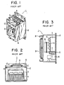
- Figs. 1 to 3 of the attached drawings an example of an inverter as a conventional control apparatus of this kind is shown in Figs. 1 to 3 of the attached drawings.
- a control apparatus 1 having generally a rectangular cross-section fins 4 of an aluminum die cast product are secured to which are mounted semi- conductor elements for a main circuit, and are adapted to dissipate heat generated from semi- conductor elements 3 constituting the main circuit.
- a fan 5 is mounted inside chassis 2 below radiating fins 4 and other elements 6 constituting the circuits are also mounted within chassis 2.
- a panel 8 which is hinged to chassis 2 by hinges 7 provided above and below thereof, respectively, at the right-hand side face as viewed in Fig. 1 so as to be opened and closed a printed circuit board 9 is mounted through insulating spacers 10.
- the constitutional parts above discribed are wired together based on circuit diagrams.
- main circuit electrical elements 3 Upon operation of the inverter apparatus, main circuit electrical elements 3 generate heat that is transferred to radiating fins 4 so that their temperature is raised, but, due to the air of fan 5 located therebelow passing through and striking thereto the temperature is lowered and the semi- conductor elements for main electrical circuit 3 are adapted to be maintained within a predetermined guarantee temperature range.
- a problem arises in the external dimension of the chassis or housing 2 to contain the apparatus, i.e. the internal volume of the housing.
- the inner volume of the housing needs to be sufficiently large enough for the heat generated from the invertor apparatus as a whole to dissipate naturally through the outer surface of the housing so that the temperature within the housing is maintained within the guarantee temperatures of the components.
- West German Utility Model Specification G 81 35 310.3 discloses a power electronic control apparatus comprising a chassis which defines a cooling air duct, ventilating means for passing air through the duct, and at least one circuit component mounted on a side wall of the chassis through an opening formed in the side wall.
- the cooling air duct decreases in width, in the direction of flow.
- a disadvantage of this construction is that a special duct construction must be provided for each different number of semi-conductor devices to be cooled. Standardised fabrication is therefore not possible.
- a power electronic control apparatus comprising a chassis which defines a cooling air duct, ventilating means for passing air through the duct, and at least one circuit component mounted on a side wall of the chassis through an opening formed in the side wall, characterised in that the chassis has its side walls formed of sheet metal, and upper and lower ends consisting of cast frames of standardised dimensions with air-flow apertures, and the ventilating means is mounted in an aperture in at least one of the said cast frames so as to pass cooling air through the air duct formed by the cast end frames and the sheet metal sides, the cast end frames being attached to the sheet metal sides.
- the sheet metal chassis preferably has a generally rectangular cross-section tube shape, with die cast hollow end frames having a cross-section similar to that of the chassis.
- the electrical circuit elements are mounted to radiating fins which are secured to the side of the chassis so as to close the opening formed therein.
- the present invention control apparatus imparts no thermal effect to other electrical circuit elements because it has a separate passage for the heated air. It can prolong the life of the electrical circuit components and increase their reliability.
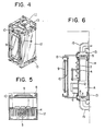
- a hollow chassis 12 of a control apparatus 11 has fins 4 secured thereto inside thereof to cause heat generated from the electrical elements 3 from the main circuit (hereinafter referred to as "semiconductor elements"), comprised of semiconductor elements to be dissipated, fins 4 being of a die cast product of aluminum and semiconductor elements 3 being mounted thereto.
- semiconductor elements comprised of semiconductor elements to be dissipated, fins 4 being of a die cast product of aluminum and semiconductor elements 3 being mounted thereto.
- chassis 12 has a rectangular cross-section and is provided with a rectangular opening in one of its side surfaces the size of which is somewhat larger than the external dimensions of semiconductor elements 3, whereby it is taken into consideration that radiating fins 4 are to be mounted to the rear surface of one of the sides of chassis 12 and are not to project past the front surface thereof.
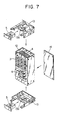
- Chassis 12 has thus a rectangular cross-section and cast frames 13 (e.g., made by an aluminum die cast process, each having generally a flat trapezoidal configuration with a base portion having a cross-section similar to that of chassis 12, fit to the open top and bottom ends of chassis 12 so as to be releasably secured thereto by such as screws.
- cast frames 13 e.g., made by an aluminum die cast process, each having generally a flat trapezoidal configuration with a base portion having a cross-section similar to that of chassis 12, fit to the open top and bottom ends of chassis 12 so as to be releasably secured thereto by such as screws.
- a fan 5 which is mounted on a mounting board to be secured thereto.
- Elements 6 constituting the other electrical circuit are mounted to chassis 12 on the front surface of the side to which fins 4 are mounted, and an openable and closeable panel 8 which is hinged to the right hand posts projected forwards from upper and lower frames 13, respectively, by hinges 7, panel 8 mounting a printed circuit board 9 thereon through insulating spacers 10.
- an openable and closeable panel 8 which is hinged to the right hand posts projected forwards from upper and lower frames 13, respectively, by hinges 7, panel 8 mounting a printed circuit board 9 thereon through insulating spacers 10.
- semi- conductor elements 3 of the main electrical circuit Upon operation of the inverter apparatus, semi- conductor elements 3 of the main electrical circuit generate heat to be conducted to radiating fins 4, raising their temperatures, but due to the passage of air by fans 5 for ventilation the temperatures of fins 4 are lowered so that the normal characteristics of main electrical circuit components 3 are maintained.
- the ventilating air flows passes through a wind channel A (see Fig. 6) constituted by upper and lower frames 13 as well as the sides of rectangular chassis 12, so no heated air impinges upon the other components.
- chassis 12 in accordance with the present invention is comprised of sheet metal members constituting its sides and cast members constituting upper and lower frames 13 detachably secured to the sheet metal members to form the upper and lower ends of chassis 12, even if it is necessary to make chassis 12 larger according to the capacity of the inverter apparatus, it can be easily adapted by merely forming the sides constituted from sheet metal into greater dimensions in height without changing the cross sectional shape and dimensions of chassis 12 and with cast frames 13 which constitute the upper and lower ends of chassis 12 being commonly utilized for any capacity inverter apparatus.
- the present invention can contribute to the standardization of production of inverter apparatuses.
- chassis 12 from cast frames 13 is aimed at strengthening chassis 12 and also facilitates the mounting of cooling fans 5.
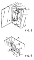
- Fig. 8 is an embodiment that indicates the state of mounting of the inverter apparatus to a control housing 16 wherein the reference numeral 15 shows flexible pipes which are respectively connected between the wind channel of the inverter apparatus 1 and the suction part 18 and discharge port 17 formed in control housing 16.
- the other members are identical to those in the prior art.
- Fig. 9 shows a further embodiment of the present invention wherein is shown a flexible pipe 15 and a duct connecting member 19 having a hollow square cross-section as connected between the wind channel of the body 1 of an inverter apparatus and the suction or discharge port of the control housing 16.
- a flexible pipe 15 and a duct connecting member 19 having a hollow square cross-section as connected between the wind channel of the body 1 of an inverter apparatus and the suction or discharge port of the control housing 16.
Landscapes
- Engineering & Computer Science (AREA)
- Microelectronics & Electronic Packaging (AREA)
- Physics & Mathematics (AREA)
- Thermal Sciences (AREA)
- Power Engineering (AREA)
- Cooling Or The Like Of Electrical Apparatus (AREA)
- Inverter Devices (AREA)
Claims (4)
Applications Claiming Priority (4)
| Application Number | Priority Date | Filing Date | Title |
|---|---|---|---|
| JP12271282U JPS5928287U (ja) | 1982-08-12 | 1982-08-12 | インバ−タ装置 |
| JP12271082U JPS5928285U (ja) | 1982-08-12 | 1982-08-12 | 制御装置 |
| JP122710/82U | 1982-08-12 | ||
| JP122712/82U | 1982-08-12 |
Publications (2)
| Publication Number | Publication Date |
|---|---|
| EP0103412A1 EP0103412A1 (fr) | 1984-03-21 |
| EP0103412B1 true EP0103412B1 (fr) | 1987-04-15 |
Family
ID=26459786
Family Applications (1)
| Application Number | Title | Priority Date | Filing Date |
|---|---|---|---|
| EP83304679A Expired EP0103412B1 (fr) | 1982-08-12 | 1983-08-12 | Appareil de contrôle pour des convertisseurs et analogues |
Country Status (3)
| Country | Link |
|---|---|
| US (1) | US4520425A (fr) |
| EP (1) | EP0103412B1 (fr) |
| DE (1) | DE3371026D1 (fr) |
Cited By (6)
| Publication number | Priority date | Publication date | Assignee | Title |
|---|---|---|---|---|
| DE19510774A1 (de) * | 1995-03-24 | 1996-09-26 | Hanning Elektro Werke | Kühleinrichtung für elektronische Bauteile |
| DE19958189A1 (de) * | 1999-12-02 | 2001-06-07 | Man Nutzfahrzeuge Ag | Kühler für motorfestes Steuergerät |
| DE20016013U1 (de) * | 2000-09-15 | 2001-11-08 | Siemens AG, 80333 München | Schaltschrank mit verbesserter Wärmeabführung |
| DE102006041400A1 (de) * | 2006-09-04 | 2008-03-13 | Ormazabal Anlagentechnik Gmbh | System zur Belüftung einer elektrischen Funktionseinheit der Hoch- und Mittelspannung |
| WO2008129134A1 (fr) * | 2007-04-23 | 2008-10-30 | Epec Oy | Procédé et dispositif pour refroidir un boîtier d'équipement |
| WO2022183257A1 (fr) * | 2021-03-01 | 2022-09-09 | PpWEG DRIVES & CONTROLS AUTOMAÇÃO LTDA. | Système et procédé de réfrigération d'un inverseur de fréquence |
Families Citing this family (73)
| Publication number | Priority date | Publication date | Assignee | Title |
|---|---|---|---|---|
| GB2153150B (en) * | 1984-01-19 | 1987-05-13 | Rank Organisation Plc | Interference suppression for semi-conducting switching devices |
| FR2580137A1 (en) * | 1985-04-05 | 1986-10-10 | Omron Tateisi Electronics Co | Assembly of electronic components |
| DE3517149A1 (de) * | 1985-05-11 | 1986-11-13 | Zinser Textilmaschinen Gmbh, 7333 Ebersbach | Kuehlvorrichtung |
| JPS6210890U (fr) * | 1985-07-04 | 1987-01-23 | ||
| DE3533057A1 (de) * | 1985-09-17 | 1987-03-26 | Swf Auto Electric Gmbh | Schalter mit einstellbarem widerstand zum steuern der leistungsaufnahme elektrischer verbraucher an kraftfahrzeugen |
| US4648007A (en) * | 1985-10-28 | 1987-03-03 | Gte Communications Systems Corporation | Cooling module for electronic equipment |
| US4691274A (en) * | 1986-04-29 | 1987-09-01 | Modular Power Corporation | Modular electronic power supply |
| DE3751064T2 (de) * | 1986-12-19 | 1995-06-08 | Fanuc Ltd | Motorantriebseinheit. |
| US4769557A (en) * | 1987-02-19 | 1988-09-06 | Allen-Bradley Company, Inc. | Modular electric load controller |
| DE3715137A1 (de) * | 1987-05-07 | 1988-11-24 | Franz Schauer | Montagetraeger mit elektrischer ueberwachungsschaltung fuer heizkreise |
| JPH0834714B2 (ja) * | 1987-06-16 | 1996-03-29 | ファナック株式会社 | Acスピンドルアンプの筐体構造 |
| DE3721901A1 (de) * | 1987-07-02 | 1989-01-12 | Heidelberger Druckmasch Ag | Schaltschrank |
| US4807441A (en) * | 1987-07-17 | 1989-02-28 | Allied-Signal Inc. | Cooling system for a sealed enclosure |
| US4923000A (en) * | 1989-03-03 | 1990-05-08 | Microelectronics And Computer Technology Corporation | Heat exchanger having piezoelectric fan means |
| JPH0719991B2 (ja) * | 1990-02-28 | 1995-03-06 | 三菱電機株式会社 | 制御装置ケース |
| DE4015030C1 (fr) * | 1990-05-10 | 1991-11-21 | Bicc-Vero Elektronics Gmbh, 2800 Bremen, De | |
| US5107398A (en) * | 1990-05-30 | 1992-04-21 | Digital Equipment Corporation | Cooling system for computers |
| JP2684897B2 (ja) * | 1991-06-24 | 1997-12-03 | 三菱電機株式会社 | 制御装置 |
| FR2683029B1 (fr) * | 1991-10-29 | 1993-12-03 | Thomson Csf | Dispositif de regulation de temperature pour boitier. |
| US5253613A (en) * | 1992-04-30 | 1993-10-19 | General Electric Company | High power AC traction inverter cooling |
| FR2714251B1 (fr) * | 1993-12-22 | 1996-01-12 | Telemecanique | Variateur électronique de vitesse. |
| DE19515121C2 (de) * | 1995-04-25 | 1998-02-26 | Kurt Wolf Gmbh & Co | Gehäuseaufbau für im Freien aufstellbare, elektrische und/oder elektronische Geräte |
| US5715140A (en) * | 1996-05-03 | 1998-02-03 | Ford Motor Company | Overlay substrate for securing electronic devices in a vehicle |
| US6233149B1 (en) * | 1997-04-23 | 2001-05-15 | General Electric Company | High power inverter air cooling |
| US6104602A (en) * | 1997-07-31 | 2000-08-15 | General Electric Company | Compact electrical equipment enclosure |
| DE19739309A1 (de) * | 1997-09-08 | 1999-03-18 | Lorch Schweisstech Gmbh | Stromversorgungseinheit |
| US5953209A (en) * | 1997-12-15 | 1999-09-14 | Intel Corporation | Push and pull dual-fan heat sink design |
| DE19926007B4 (de) * | 1998-07-09 | 2004-08-19 | Georg Fischer Rohrleitungssysteme Ag | Gehäuseeinheit |
| DE19831718A1 (de) * | 1998-07-15 | 2000-01-20 | Alcatel Sa | Schrank für die Aufnahme von Wärme erzeugenden elektrischen Einrichtungen |
| GB9928862D0 (en) * | 1999-12-08 | 2000-02-02 | Pace Micro Tech Plc | Means for dissipating heat to electrical apparatus |
| FR2826831B1 (fr) * | 2001-06-29 | 2003-10-24 | Peugeot Citroen Automobiles Sa | Dsipositif de refroidissement d'au moins un module electronique de puissance, par exemple pour un vehicule automobile |
| US6912128B2 (en) * | 2001-08-09 | 2005-06-28 | Celestica International Inc. | Electronics cooling subassembly |
| CA2462444A1 (fr) * | 2001-10-04 | 2003-04-10 | Celestica International Inc. | Systeme de refroidissement a emplacement de ventilation independant |
| EP1343362A1 (fr) * | 2002-03-07 | 2003-09-10 | Hewlett-Packard Company (a Delaware corporation) | Système de refroidissement pour des appareils électroniques |
| JP2004040069A (ja) * | 2002-07-01 | 2004-02-05 | Chin Kuang Luo | 熱放散装置 |
| US7031156B2 (en) * | 2003-07-25 | 2006-04-18 | Rockwell Automation Technologies, Inc. | Reduced package volume convectively cooled sealed electrical system and method |
| JP2005044953A (ja) * | 2003-07-28 | 2005-02-17 | Hitachi Industrial Equipment Systems Co Ltd | 電力変換装置 |
| US7418995B2 (en) * | 2004-01-14 | 2008-09-02 | Vanner, Inc. | System for cooling environmentally sealed enclosures |
| JP4265505B2 (ja) * | 2004-08-09 | 2009-05-20 | オムロン株式会社 | 電子機器の放熱構造 |
| CN101080961A (zh) * | 2004-12-17 | 2007-11-28 | 绍勒有限责任两合公司 | 用于冷却纺织机驱动机组大功率电子装置的方法和装置 |
| JP4015164B2 (ja) * | 2005-08-10 | 2007-11-28 | ファナック株式会社 | 電子機器の筐体構造 |
| US7307840B2 (en) * | 2005-10-14 | 2007-12-11 | Smiths Aerospace Llc | Cross-flow redundant air cooling method for high reliability electronics |
| JP4935193B2 (ja) * | 2006-05-31 | 2012-05-23 | 富士電機株式会社 | インバータ装置 |
| US20070285889A1 (en) * | 2006-06-12 | 2007-12-13 | Watson Mark A | Forced air cooled electrical box for mining equipment |
| US20080061046A1 (en) * | 2006-09-13 | 2008-03-13 | Hypertherm, Inc. | Power Supply Cooling System |
| DE102006052431A1 (de) * | 2006-11-07 | 2008-05-08 | BSH Bosch und Siemens Hausgeräte GmbH | Hausgerät mit einem Energieverbraucher und einer Steuerelektronik zum Steuern des Energieverbrauchers |
| US20080112135A1 (en) * | 2006-11-10 | 2008-05-15 | Toshiba International Corporation | Outdoor Medium Voltage Drive |
| DE102007003329B3 (de) * | 2007-01-17 | 2008-04-10 | Siemens Ag | Kühlanordnung für in einem Gehäuse angeordnete elektrische Komponenten eines Sanftanlaufgerätes, und Sanftanlaufgerät |
| DE202007011801U1 (de) * | 2007-08-23 | 2009-01-02 | Dometic Waeco International Gmbh | Stromversorgungsgerät für den Freizeit- und Automobilbereich |
| FI122888B (fi) * | 2007-10-08 | 2012-08-31 | Vacon Oyj | Tehoelektroniikkalaitteiston kotelointijärjestely |
| WO2009115375A1 (fr) * | 2008-03-17 | 2009-09-24 | Amsler Tex Ag | Dispositif avec élément de puissance refroidi pour la fabrication de fil fantaisie |
| DE102008027757A1 (de) * | 2008-06-11 | 2009-11-05 | Siemens Aktiengesellschaft | Umrichter-Einbaugerät |
| US9192079B2 (en) * | 2008-09-26 | 2015-11-17 | Rockwell Automation Technologies, Inc. | Power electronic module cooling system and method |
| DE102008060613B4 (de) * | 2008-12-09 | 2022-09-15 | Sew-Eurodrive Gmbh & Co Kg | Kühlanordnung für einen in einem Schaltschrank angeordneten Umrichter |
| WO2011059644A1 (fr) * | 2009-11-11 | 2011-05-19 | Nextronex Energy Systems, Llc | Système inverseur |
| JP5344182B2 (ja) * | 2010-02-02 | 2013-11-20 | 株式会社安川電機 | 電力変換装置 |
| JP5348623B2 (ja) * | 2010-09-10 | 2013-11-20 | 株式会社安川電機 | 電子機器装置 |
| KR101189451B1 (ko) * | 2010-12-24 | 2012-10-09 | 엘지전자 주식회사 | 인버터 스택 |
| US9429151B2 (en) | 2011-05-17 | 2016-08-30 | Carrier Corporation | Variable frequency drive heat sink assembly |
| US8611088B2 (en) * | 2011-11-16 | 2013-12-17 | Cooper Technologies Company | Mechanical heat pump for an electrical housing |
| DE102012001120A1 (de) * | 2012-01-23 | 2013-07-25 | Sew-Eurodrive Gmbh & Co. Kg | Vorrichtung, insbesondere Schaltschrank, mit Gehäuse |
| DE102013109575A1 (de) * | 2013-09-03 | 2015-03-05 | DESITECK Diez Energy Solutions GmbH | Elektronische Spannungs- oder Stromversorgungseinheit |
| EP2983460A1 (fr) * | 2014-08-07 | 2016-02-10 | Alcatel Lucent | Appareil et procédé de refroidissement d'un châssis d'équipement électronique |
| US9338907B2 (en) * | 2014-09-24 | 2016-05-10 | Hil Tech Llc | Thermally managed enclosure |
| DE102015105500B3 (de) * | 2015-04-10 | 2016-09-08 | Rittal Gmbh & Co. Kg | Kühlgerät für die Schaltschrankklimatisierung |
| US10197052B2 (en) * | 2015-05-11 | 2019-02-05 | Littelfuse, Inc. | Variable frequency drive apparatus |
| JP6294263B2 (ja) * | 2015-07-06 | 2018-03-14 | ファナック株式会社 | ファンモータを交換できるモータ駆動装置、およびこれを備えた制御盤 |
| JP2017045775A (ja) * | 2015-08-24 | 2017-03-02 | 株式会社東芝 | 送信機および電子機器 |
| JP6701701B2 (ja) * | 2015-12-04 | 2020-05-27 | 富士電機株式会社 | インバータ装置 |
| CN206061354U (zh) | 2016-09-30 | 2017-03-29 | 阳光电源股份有限公司 | 一种机箱及具有所述机箱的电子设备 |
| EP3490087A1 (fr) * | 2017-11-27 | 2019-05-29 | Siemens Aktiengesellschaft | Dissipation thermique d'armoire électrique |
| KR102671866B1 (ko) | 2019-01-17 | 2024-05-31 | 엘에스일렉트릭(주) | 인버터용 방열모듈 |
| EP3819139A1 (fr) * | 2019-11-08 | 2021-05-12 | Volvo Car Corporation | Module d'accueil et de refroidissement de circuits électroniques dans un véhicule |
Family Cites Families (9)
| Publication number | Priority date | Publication date | Assignee | Title |
|---|---|---|---|---|
| DE1046199B (de) * | 1956-12-01 | 1958-12-11 | Standard Elektrik Lorenz Ag | Gehaeuse mit Montagezwischenwand fuer Gleichrichtergeraete |
| US3198991A (en) * | 1964-02-26 | 1965-08-03 | Gen Electric | Air cooled electronic enclosure |
| US3305704A (en) * | 1964-06-26 | 1967-02-21 | Itt | Power supply heat sink |
| DE7003178U (de) * | 1970-01-30 | 1970-05-14 | Neumann Elektronik Gmbh | Elektronisches geraet. |
| US3993123A (en) * | 1975-10-28 | 1976-11-23 | International Business Machines Corporation | Gas encapsulated cooling module |
| FR2343974A1 (fr) * | 1976-03-10 | 1977-10-07 | Honeywell Bull Soc Ind | Enceinte de ventilation |
| US4166665A (en) * | 1976-12-27 | 1979-09-04 | Cutchaw John M | Liquid cooled connector for large scale integrated circuit packages |
| DE3041656A1 (de) * | 1980-11-05 | 1982-05-13 | SEMIKRON Gesellschaft für Gleichrichterbau u. Elektronik mbH, 8500 Nürnberg | Halbleiter-schaltungsaufbau |
| DE8135310U1 (de) * | 1981-12-01 | 1982-08-05 | Licentia Patent-Verwaltungs-Gmbh, 6000 Frankfurt | Kühlluftkanal eines elektronischen Gerätes mit Luftkühlung |
-
1983
- 1983-08-10 US US06/521,917 patent/US4520425A/en not_active Expired - Fee Related
- 1983-08-12 EP EP83304679A patent/EP0103412B1/fr not_active Expired
- 1983-08-12 DE DE8383304679T patent/DE3371026D1/de not_active Expired
Cited By (8)
| Publication number | Priority date | Publication date | Assignee | Title |
|---|---|---|---|---|
| DE19510774A1 (de) * | 1995-03-24 | 1996-09-26 | Hanning Elektro Werke | Kühleinrichtung für elektronische Bauteile |
| DE19958189A1 (de) * | 1999-12-02 | 2001-06-07 | Man Nutzfahrzeuge Ag | Kühler für motorfestes Steuergerät |
| DE20016013U1 (de) * | 2000-09-15 | 2001-11-08 | Siemens AG, 80333 München | Schaltschrank mit verbesserter Wärmeabführung |
| DE102006041400A1 (de) * | 2006-09-04 | 2008-03-13 | Ormazabal Anlagentechnik Gmbh | System zur Belüftung einer elektrischen Funktionseinheit der Hoch- und Mittelspannung |
| DE102006041400B4 (de) * | 2006-09-04 | 2008-07-03 | Ormazabal Anlagentechnik Gmbh | System zur Belüftung einer elektrischen Funktionseinheit der Hoch- und Mittelspannung |
| WO2008129134A1 (fr) * | 2007-04-23 | 2008-10-30 | Epec Oy | Procédé et dispositif pour refroidir un boîtier d'équipement |
| WO2022183257A1 (fr) * | 2021-03-01 | 2022-09-09 | PpWEG DRIVES & CONTROLS AUTOMAÇÃO LTDA. | Système et procédé de réfrigération d'un inverseur de fréquence |
| US12432890B2 (en) | 2021-03-01 | 2025-09-30 | Weg Drives & Controls Automacao Ltda. | System and method for cooling a frequency inverter |
Also Published As
| Publication number | Publication date |
|---|---|
| EP0103412A1 (fr) | 1984-03-21 |
| US4520425A (en) | 1985-05-28 |
| DE3371026D1 (en) | 1987-05-21 |
Similar Documents
| Publication | Publication Date | Title |
|---|---|---|
| EP0103412B1 (fr) | Appareil de contrôle pour des convertisseurs et analogues | |
| US5235491A (en) | Safety power supply | |
| US5424915A (en) | Cooling structure for power supply device | |
| CN1235509A (zh) | 有密封外壳的电子设备 | |
| PL70978B1 (fr) | ||
| KR880007977A (ko) | 제어 모듈 냉각 시스템 | |
| CN116430657A (zh) | 全密闭式防护箱 | |
| JP2000190163A (ja) | 制御盤 | |
| JPWO2018061071A1 (ja) | 空気調和機の室外機 | |
| JP2003258463A (ja) | 筐体の熱交換構造 | |
| KR100212600B1 (ko) | 반도체 ic 시험 장치용 일체형 밀폐 케이스 냉각 장치 | |
| CN209930817U (zh) | 电器盒结构及具有其的空调器 | |
| JP2001128321A (ja) | 配電盤の冷却装置 | |
| JPH07100732A (ja) | 制御盤 | |
| CN216391864U (zh) | 一种矿车用控制柜及矿车 | |
| JP2895388B2 (ja) | プリント基板の冷却構造 | |
| JPH0590776A (ja) | プリント板ユニツト | |
| CN111684209A (zh) | 室外机及空气调节机 | |
| JPH06288580A (ja) | 空気調和装置の室外ユニット | |
| JP2712840B2 (ja) | 空気調和機の天吊形室外機 | |
| CN220653869U (zh) | 基于散热的隔离网闸 | |
| CN218242712U (zh) | 一种散热通风的新型防爆柜 | |
| CN219740208U (zh) | 变频柜和暖通设备 | |
| JPH0465192A (ja) | 電子機器のシェルフ構造 | |
| JP2868485B2 (ja) | 電子機器筐体の放熱装置 |
Legal Events
| Date | Code | Title | Description |
|---|---|---|---|
| PUAI | Public reference made under article 153(3) epc to a published international application that has entered the european phase |
Free format text: ORIGINAL CODE: 0009012 |
|
| AK | Designated contracting states |
Designated state(s): DE FR GB |
|
| 17P | Request for examination filed |
Effective date: 19840508 |
|
| GRAA | (expected) grant |
Free format text: ORIGINAL CODE: 0009210 |
|
| AK | Designated contracting states |
Kind code of ref document: B1 Designated state(s): DE FR GB |
|
| REF | Corresponds to: |
Ref document number: 3371026 Country of ref document: DE Date of ref document: 19870521 |
|
| ET | Fr: translation filed | ||
| PLBE | No opposition filed within time limit |
Free format text: ORIGINAL CODE: 0009261 |
|
| STAA | Information on the status of an ep patent application or granted ep patent |
Free format text: STATUS: NO OPPOSITION FILED WITHIN TIME LIMIT |
|
| 26N | No opposition filed | ||
| PGFP | Annual fee paid to national office [announced via postgrant information from national office to epo] |
Ref country code: GB Payment date: 19920731 Year of fee payment: 10 |
|
| PGFP | Annual fee paid to national office [announced via postgrant information from national office to epo] |
Ref country code: FR Payment date: 19920807 Year of fee payment: 10 |
|
| PGFP | Annual fee paid to national office [announced via postgrant information from national office to epo] |
Ref country code: DE Payment date: 19920824 Year of fee payment: 10 |
|
| PG25 | Lapsed in a contracting state [announced via postgrant information from national office to epo] |
Ref country code: GB Effective date: 19930812 |
|
| GBPC | Gb: european patent ceased through non-payment of renewal fee |
Effective date: 19930812 |
|
| PG25 | Lapsed in a contracting state [announced via postgrant information from national office to epo] |
Ref country code: FR Effective date: 19940429 |
|
| PG25 | Lapsed in a contracting state [announced via postgrant information from national office to epo] |
Ref country code: DE Effective date: 19940503 |
|
| REG | Reference to a national code |
Ref country code: FR Ref legal event code: ST |