EP0100989B1 - Vorrichtung zum Behandeln einer körnigen Substanz, insbesondere von Kernreaktorbrennstoff in Pulverform, und Verfahren zum Betrieb der Vorrichtung - Google Patents
Vorrichtung zum Behandeln einer körnigen Substanz, insbesondere von Kernreaktorbrennstoff in Pulverform, und Verfahren zum Betrieb der Vorrichtung Download PDFInfo
- Publication number
- EP0100989B1 EP0100989B1 EP83107566A EP83107566A EP0100989B1 EP 0100989 B1 EP0100989 B1 EP 0100989B1 EP 83107566 A EP83107566 A EP 83107566A EP 83107566 A EP83107566 A EP 83107566A EP 0100989 B1 EP0100989 B1 EP 0100989B1
- Authority
- EP
- European Patent Office
- Prior art keywords
- treatment drum
- cover
- central axis
- partial
- treatment
- Prior art date
- Legal status (The legal status is an assumption and is not a legal conclusion. Google has not performed a legal analysis and makes no representation as to the accuracy of the status listed.)
- Expired
Links
Images


Classifications
-
- B—PERFORMING OPERATIONS; TRANSPORTING
- B02—CRUSHING, PULVERISING, OR DISINTEGRATING; PREPARATORY TREATMENT OF GRAIN FOR MILLING
- B02C—CRUSHING, PULVERISING, OR DISINTEGRATING IN GENERAL; MILLING GRAIN
- B02C17/00—Disintegrating by tumbling mills, i.e. mills having a container charged with the material to be disintegrated with or without special disintegrating members such as pebbles or balls
- B02C17/18—Details
Definitions
- the invention relates to a device for treating a granular substance, in particular nuclear reactor fuel in powder form, with a treatment drum which is rotatably mounted about a central axis and can be driven about this central axis by means of an associated drive unit and which has a closure cap at one end, and a method for Operation of the device.
- the treatment drum which can be filled with grinding balls, is closed at one end with a one-piece closure cover, which is pressed with the aid of a screw from the outside into the filling opening of the treatment drum located at this end.
- the screw is guided in a threaded bore which is located in a web arranged transversely above the opening with a cover which is held at both ends by a ring which is clamped on the outside of the outer surface of the treatment drum.
- the treatment drum is loosely mounted with its outer lateral surface and with a horizontal central axis between two cylindrical rollers on the lateral surfaces of these two rollers, which are arranged side by side with horizontal and mutually parallel longitudinal axes.
- One of these rollers is driven about its longitudinal axis with the help of an electric motor and thus represents the drive unit assigned to the treatment drum, with which the treatment drum can be driven and rotated about its central axis.
- the granular substance to be treated must be poured manually into the opened treatment drum arranged with a vertical central axis and poured out of the treatment drum again after treatment. This inevitably results in considerable dust formation, which, particularly in the case of toxic or radioactive (e.g. plutonium-containing) granular substance, can endanger the operating personnel.
- the object of the invention is to remedy this and to enable the device for treating a granular substance to be filled and emptied as dust-free as possible.
- a device of the type mentioned at the outset is characterized according to the invention in that the closure lid has two partial lids located next to one another in the direction of the central axis of the treatment drum, which can be rotated relative to one another about the central axis between two stop points by means of a lid drive unit, and of which the outer partial lid an opening for docking a substance container and the inner partial lid has a through opening that is aligned with the opening for docking at one of the two attachment points and that is closed at the other attachment point by the outer partial lid, and that the treatment drum is about a pivot axis that is perpendicular to its central axis is pivotable with the help of a swivel unit.
- the treatment drum can be pivoted so far about the pivot axis that is perpendicular to its central axis that the closure cover is located at the lower end of the central axis. Then the substance container in which the granular substance is e.g. was transported and / or stored, opened and docked with its opening to the opening of the outer partial cover. Every spill of the granular substance and thus any dust can be avoided. Then the two part lids of the closure lid are rotated against each other with the aid of the lid drive unit up to the stop point in which the through opening in the inner part lid is aligned with the opening for docking the substance container in the outer part lid.
- the treatment drum is then pivoted about the pivot axis until the cover is at the upper end of the center axis of the treatment drum.
- the granular substance is transferred from the substance container into the treatment drum without releasing dust.
- This transfer process can be supported by turning the treatment drum around its central axis.
- the two partial lids of the closure lid are rotated again in another direction against each other about the central axis until the through opening in the inner partial lid is closed by the outer partial lid at the other stop point.
- the treatment drum can then be pivoted about the pivot axis until the center axis of the treatment drum is horizontal. Treatment of the granular substance in the treatment drum can then be started by rotating this treatment drum about its central axis. Here, too, any dust release is avoided.
- the treatment drum is pivoted again about the pivot axis perpendicular to its central axis until the cover plate is at the lower end of the central axis.
- the through opening in the inner partial cover of the closure cover is then opened, as already described, so that the pretreated granular substance can get from the treatment drum into the substance container.
- the treatment drum can now also be rotated about its central axis.
- the substance container with the granular substance can be undocked and closed from the outer partial cover.
- the granular substance which has been poured into the treatment drum from the substance container docked on the outer part cover is pretreated by rotating the treatment drum around its central axis, then filled through the closure cover into the substance container docked on the outer part cover and then underneath Rotating the treatment drum together with the docked substance container is post-treated about the center axis of the treatment drum.
- This post-treatment can be carried out with the center axis of the treatment drum positioned horizontally and e.g. a build-up granulation of the granular substance located in the substance container.
- This aftertreatment also takes place without the release of dust.
- the substance container with the aftertreated granular substance can also be undocked from the outer partial cover of the sealing cover and closed without dust release, as already described above.
- the device for treating a granular substance can be designed in a relatively compact design and is therefore also particularly suitable for use in a confined space, e.g. in glove boxes, such as those required for plutonium technology.
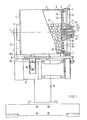
- FIGS. 1-3 schematically show the device according to FIGS. 1-3 in different operating states.
- the device according to FIGS. 1 to 3 has a hollow cylindrical treatment drum 2 with a central axis 3.
- the treatment drum 2 has a bottom 4 and a sealing cover with an outer partial cover 5 and an inner partial cover 6. Both partial covers 5 and 6 are arranged coaxially to the treatment drum 2. They can be rotated relative to one another about the central axis 3.
- the inner partial cover 6 is advantageously rigidly and tightly connected to the treatment drum 2 by means of screws 7.
- the bottom 4 of the treatment drum 2 is held in the center via a ball bearing 8 on one leg 9a of an angular part 9, the other leg 9b of which is pivotally mounted on a stand 10 about a pivot axis 11.
- the leg 9b of the angle part 9 held on the stand 10 carries two support rollers 12, the longitudinal axes of which are parallel to the central axis 3 of the treatment drum 2, between which the treatment drum 2 is located and on the outer surfaces of which the treatment drum 2 rests with its outer outer surface.
- a drive motor 13 is arranged on the angle part 9 as a drive unit assigned to the treatment drum 2, with a drive belt 14 which engages on the outer surface of the outer part cover 5 of the closure cover of the treatment drum 2.
- This drive belt 14 is also assigned a tensioning element 15 seated on the angle part 9.
- an electromagnet 16 is seated on the angle part 9 opposite the casing of the treatment drum 2 as a braking unit for the treatment drum 2.
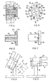
- the inner cover part 6 has on the outside in the center a hollow cylindrical collar 30 on which the outer part cover 5 is supported with a central through hole 31.
- a cylindrical coupling part 32 of a one-way clutch engages in this bore 31 from the outside of the outer part cover 5, which is fastened to the cylindrical collar 30 with axially parallel screws 33 and on which the outer part cover 5 is also mounted.
- An annular flange 32a is located on the outer end of the cylindrical coupling part 32. On the flat inner end face of this flange 32a there are milling cutouts 32b spanning the same angular distances seen, which have the same angular distance from one another and which at their ends merge into the inner end face of the flange 32a via inclined planes 32c.
- a pressure ring 34 is screwed onto the outside of the partial cover 5 coaxially with the central bore 31 together with an annular, likewise coaxial ball cage 35 with the aid of axially directed screws 36.
- the ball cage 35 is located between the pressure ring 34 and the flange 32a.
- a steel ball 37 which is positioned in the ball cage 35.
- openings 40 are provided for docking a substance container 41 each. These openings 40 have the same angular distance from one another with respect to the central axis 3 of the treatment drum 2.
- Four through openings 42 each associated with an opening 40 in the outer partial cover 5 are arranged in the inner partial cover 6. These through openings 42 also have the same angular distance from one another with respect to the central axis 3 of the treatment drum 2.
- These grinding media can be steel balls. It is advantageous if a sieve 44 is attached in each of the openings 40 of the outer partial cover 5, the mesh size of which is selected such that the grinding media of the bed 43 in the treatment drum 2 do not pass through these sieves 44 and therefore do not pass through the openings 42 and 40 can get out of the treatment drum 2.
- a feed opening (not shown) for an additive substance is provided in the bottom 4 of the treatment drum 2 at the piercing point of the central axis 3, through which a grinding aid can be introduced into the treatment drum 2, for example, even during the rotation of the treatment drum 2 about its central axis 3 .
- the treatment drum 2 For the docking of, for example, U0 2 and Pu0 2 powder-containing substance containers 41 in the four openings 40 of the outer partial cover 5, the treatment drum 2 is pivoted into the position shown in broken lines in FIG. 8 about the pivot axis 11, in which the partial cover 5 is located the lower end of the axis of rotation 3. The opened substance containers 41 are then docked in the openings 40 of the outer partial cover 5.
- the treatment drum 2 is then pivoted about the pivot axis 11 until the outer partial cover 5 with the substance containers 41 docked there are located at the upper end of the center axis 3 of the treatment drum 2.
- the treatment drum 2 is set in rotation about the central axis 3 with the aid of the drive motor 14 which represents the drive unit of the treatment drum 2.
- the drive unit i.e. the electric motor 13
- the treatment drum 2 is arranged together with the treatment drum 2 so that it can be pivoted about its pivot axis 11, since a simple V-belt 14 is then sufficient for transmitting the torque from the drive unit to the outer part cover 5.
- the direction of rotation of the treatment drum 2 about its central axis 3 is selected such that the balls 37 of the one-way clutch between the two partial covers 5 and 6 are pressed from the outer partial cover 5 against those inclined planes 32c of the cutouts 32b which represent a stop, from the outer partial cover 5, at which the docking openings 40 in the outer partial cover 5 are aligned with one of the through openings 42 in the inner partial cover 6.
- the oxide powder located in the substance containers 41 as a granular substance can thus pass through the sealing cover formed from the two partial covers 5 and 6 into the interior of the treatment drum 2.
- the outer partial cover 5 rotates with respect to the inner partial cover 6 about the central axis 3 of the treatment drum 2 until the steel balls 37 of the one-way clutch between the two partial covers 5 and 6 against the inclined planes 32c which represent the second stop on the other ends of the cutouts 32b the inner end face of the flange 32a.
- the docking openings 40 and the through openings 42 are each closed by the inner partial cover 6 or the outer partial cover 5. Furthermore, both partial covers are pressed against one another by the steel balls 37 of the one-way clutch, forming a dust-tight seal.
- the drive unit 13 formed by the drive motor for the treatment drum 2 in the device shown in the drawing is thus also the cover drive unit for the closure cover formed by the partial covers 5 and 6, which on the one of the two partial covers, namely on the outer partial cover 5, of the closure cover attacks which is rotatable relative to the treatment drum 2.
- the treatment drum 2 is braked by a brake unit, which is formed by a brake shoe 16a with an associated electromagnet 16.
- the brake shoe 16a increases the moment of inertia of the treatment drum 2 in such a way that the outer partial cover 5 can be rotated without difficulty with respect to the other partial cover 6, at which the docking openings 40 and the through openings 42 are closed. After these openings have been closed, the electromagnet 16 can be switched off again.
- this treatment drum 2 is pivoted about the pivot axis 11 into the working position in which the central axis 3 of the treatment drum 2 is horizontal and in which the treatment drum 2 is driven by means of the drive motor 13 and the drive belt 14 via the outer part cover 5 is that the one-way clutch located between the partial covers 5 and 6 keeps the docking openings 40 in the outer partial cover 5 and the through openings 42 in the inner partial cover 6 closed in a dust-tight manner.
- the oxide powder filled into the treatment drum 2 is subjected there to a pretreatment consisting of grinding in the working position of the treatment drum 2 shown in FIG. 9.
- the treatment drum 2 is pivoted again into the docking or emptying position shown in dashed lines in FIG. 8 about the pivot axis 11.
- the direction of rotation of the treatment drum 2 is then reversed about its central axis 3, so that each of the docking openings 40 in the outer partial cover 5 'is brought into alignment with the corresponding through opening 42 in the partial cover 6.
- the moment of inertia of the treatment drum 3 can be temporarily increased with the help of the electromagnet 16 acting as a braking unit.
- the oxide powder pretreated by grinding in the treatment drum 2 now passes through the openings 40 and 42 into the substance container 41 docked on the outside on the outer cover 5.
- the openings 40 for docking the substance containers 41 on the outer partial cover 5 and the through openings 42 on the inner partial cover 6 are located on the outer edge of the closure cover, thereby ensuring that the oxide powder to be filled into the substance containers 41 is completely emptied from the treatment drum 2 is.
- Substance container 41 can also be carried out several times with the same oxide powder.
- the drive unit for the treatment drum 2 the cover drive unit, which in the exemplary embodiment shown is identical to the drive unit for the treatment drum, and the swivel unit are assigned an automatic control unit.
Landscapes
- Engineering & Computer Science (AREA)
- Food Science & Technology (AREA)
- Crushing And Grinding (AREA)
- Finish Polishing, Edge Sharpening, And Grinding By Specific Grinding Devices (AREA)
- Glanulating (AREA)
- Mixers With Rotating Receptacles And Mixers With Vibration Mechanisms (AREA)
Applications Claiming Priority (2)
| Application Number | Priority Date | Filing Date | Title |
|---|---|---|---|
| DE3230039 | 1982-08-12 | ||
| DE3230039A DE3230039C2 (de) | 1982-08-12 | 1982-08-12 | Vorrichtung zum Behandeln einer körnigen Substanz, insbesondere von Kernreaktorbrennstoff in Pulverform, und Verfahren zum Betrieb der Vorrichtung |
Publications (3)
| Publication Number | Publication Date |
|---|---|
| EP0100989A2 EP0100989A2 (de) | 1984-02-22 |
| EP0100989A3 EP0100989A3 (en) | 1985-08-21 |
| EP0100989B1 true EP0100989B1 (de) | 1987-04-22 |
Family
ID=6170712
Family Applications (1)
| Application Number | Title | Priority Date | Filing Date |
|---|---|---|---|
| EP83107566A Expired EP0100989B1 (de) | 1982-08-12 | 1983-08-01 | Vorrichtung zum Behandeln einer körnigen Substanz, insbesondere von Kernreaktorbrennstoff in Pulverform, und Verfahren zum Betrieb der Vorrichtung |
Country Status (4)
| Country | Link |
|---|---|
| US (1) | US4582268A (ja) |
| EP (1) | EP0100989B1 (ja) |
| BE (1) | BE897464A (ja) |
| DE (2) | DE3230039C2 (ja) |
Families Citing this family (8)
| Publication number | Priority date | Publication date | Assignee | Title |
|---|---|---|---|---|
| US4801100A (en) * | 1985-03-15 | 1989-01-31 | Inco Alloys International, Inc. | System for discharging ball mills |
| US4705222A (en) * | 1985-05-03 | 1987-11-10 | Processall, Inc. | Multipurpose mixer |
| DE3538991A1 (de) * | 1985-11-02 | 1987-05-21 | Krupp Gmbh | Verfahren zur feinstzerkleinerung von mineralischen stoffen und vorrichtung zur durchfuehrung des verfahrens |
| DE4434707A1 (de) * | 1994-09-28 | 1996-04-04 | Siemens Ag | Trommelmühle |
| JPH1144792A (ja) * | 1997-07-28 | 1999-02-16 | Power Reactor & Nuclear Fuel Dev Corp | 遠隔蓋開閉型粉末用気送容器 |
| FR2786116B1 (fr) * | 1998-11-19 | 2001-01-12 | Franco Belge Combustibles | Procede et installation de traitement d'une poudre combustible nucleaire |
| WO2012123347A2 (de) * | 2011-03-11 | 2012-09-20 | Willy A. Bachofen Ag | Rührwerkskugelmühle |
| CN108295990A (zh) * | 2018-01-25 | 2018-07-20 | 中国原子能科学研究院 | 一种核材料粉碎装置 |
Family Cites Families (9)
| Publication number | Priority date | Publication date | Assignee | Title |
|---|---|---|---|---|
| DE214975C (ja) * | ||||
| US965813A (en) * | 1908-11-27 | 1910-07-26 | Hubert M Greist | Tumbling-barrel. |
| US1517538A (en) * | 1922-07-22 | 1924-12-02 | Arthur C Daman | Crushing mill |
| DE628977C (de) * | 1934-12-13 | 1936-04-20 | Fried Krupp Grusonwerk Akt Ges | Zwischenwand fuer Trommelmuehlen |
| US3157364A (en) * | 1961-10-09 | 1964-11-17 | Hitachi Ltd | Method of pulverizing graphite |
| US3325066A (en) * | 1965-10-22 | 1967-06-13 | Continental Can Co | Dispensing container having a rotary closure cap |
| BE698675A (ja) * | 1967-05-19 | 1967-11-20 | ||
| US3644104A (en) * | 1968-10-23 | 1972-02-22 | Georges Manevy | Process for processing canned irradiated ceramic fuel elements |
| US3825230A (en) * | 1972-05-04 | 1974-07-23 | Boardman Co | Safe geometry nuclear fuel powder blender |
-
1982
- 1982-08-12 DE DE3230039A patent/DE3230039C2/de not_active Expired
-
1983
- 1983-08-01 DE DE8383107566T patent/DE3371043D1/de not_active Expired
- 1983-08-01 EP EP83107566A patent/EP0100989B1/de not_active Expired
- 1983-08-04 BE BE0/211302A patent/BE897464A/fr not_active IP Right Cessation
- 1983-08-09 US US06/521,703 patent/US4582268A/en not_active Expired - Fee Related
Also Published As
| Publication number | Publication date |
|---|---|
| BE897464A (fr) | 1983-12-01 |
| DE3371043D1 (en) | 1987-05-27 |
| US4582268A (en) | 1986-04-15 |
| DE3230039C2 (de) | 1984-11-08 |
| DE3230039A1 (de) | 1984-02-16 |
| EP0100989A2 (de) | 1984-02-22 |
| EP0100989A3 (en) | 1985-08-21 |
Similar Documents
| Publication | Publication Date | Title |
|---|---|---|
| DE3333029C2 (ja) | ||
| DE3642938A1 (de) | Kraftbetaetigungsvorrichtung | |
| EP0100989B1 (de) | Vorrichtung zum Behandeln einer körnigen Substanz, insbesondere von Kernreaktorbrennstoff in Pulverform, und Verfahren zum Betrieb der Vorrichtung | |
| EP0125389B1 (de) | Vorrichtung zum Aufbereiten von fliessfähigen Materialien | |
| DE2145374A1 (de) | Schuettgutbehaelter | |
| DE3333459A1 (de) | Fliehkraftbearbeitungsmaschine | |
| CH643465A5 (de) | Filteranlage. | |
| DE3421777A1 (de) | Verfahren und vorrichtung zum anordnen von kapseln mit aufsatz in einer richtung | |
| DE1277126B (de) | Bestrahlungsfoerderanlage | |
| DE4036697C2 (de) | Beschichtungsmaschine zum Beschichten von Tabletten mit Transportwagen | |
| DE1607469B1 (de) | Planetenmuehle | |
| CH681955A5 (ja) | ||
| DE1941831A1 (de) | Mischmaschine | |
| AT507227B1 (de) | Mischvorrichtung | |
| CH680753A5 (ja) | ||
| EP0031879B1 (de) | Einrichtung zum Einbetonieren von radioaktiven Abfällen in Abfallfässern | |
| DE2646182A1 (de) | Vorrichtung zum automatischen laeppen eines ventilsitzes von einem absperrschieberventil | |
| DE3025048C2 (de) | Einrichtung zur Abmessung von Granularmaterialien | |
| DE1607469C (de) | Planetenmühle | |
| DE102012111748A1 (de) | Füllmaschine | |
| EP0494166B1 (de) | Zuführvorrichtung für die dämpfungsflüssigkeit in führungsrohren bei mehrspindel-drehmaschinen und dergleichen | |
| DE2728200C2 (de) | Sävorrichtung | |
| AT258629B (de) | Vorrichtung zum Streuen von Kunstdünger od. dgl. | |
| Adelmann | Device for treating a grain substance, particularly nuclear reactor fuel in powder form and process for operating the device | |
| DE3236538A1 (de) | Werkzeug zum drehen eines gewindekopfes |
Legal Events
| Date | Code | Title | Description |
|---|---|---|---|
| PUAI | Public reference made under article 153(3) epc to a published international application that has entered the european phase |
Free format text: ORIGINAL CODE: 0009012 |
|
| AK | Designated contracting states |
Designated state(s): DE FR GB |
|
| 17P | Request for examination filed |
Effective date: 19841220 |
|
| PUAL | Search report despatched |
Free format text: ORIGINAL CODE: 0009013 |
|
| AK | Designated contracting states |
Designated state(s): DE FR GB |
|
| RHK1 | Main classification (correction) |
Ipc: B02C 15/00 |
|
| 17Q | First examination report despatched |
Effective date: 19860319 |
|
| GRAA | (expected) grant |
Free format text: ORIGINAL CODE: 0009210 |
|
| AK | Designated contracting states |
Kind code of ref document: B1 Designated state(s): DE FR GB |
|
| REF | Corresponds to: |
Ref document number: 3371043 Country of ref document: DE Date of ref document: 19870527 |
|
| ET | Fr: translation filed | ||
| PLBE | No opposition filed within time limit |
Free format text: ORIGINAL CODE: 0009261 |
|
| STAA | Information on the status of an ep patent application or granted ep patent |
Free format text: STATUS: NO OPPOSITION FILED WITHIN TIME LIMIT |
|
| 26N | No opposition filed | ||
| PGFP | Annual fee paid to national office [announced via postgrant information from national office to epo] |
Ref country code: GB Payment date: 19960718 Year of fee payment: 14 |
|
| PGFP | Annual fee paid to national office [announced via postgrant information from national office to epo] |
Ref country code: FR Payment date: 19960830 Year of fee payment: 14 |
|
| PGFP | Annual fee paid to national office [announced via postgrant information from national office to epo] |
Ref country code: DE Payment date: 19961022 Year of fee payment: 14 |
|
| PG25 | Lapsed in a contracting state [announced via postgrant information from national office to epo] |
Ref country code: GB Free format text: LAPSE BECAUSE OF NON-PAYMENT OF DUE FEES Effective date: 19970801 |
|
| GBPC | Gb: european patent ceased through non-payment of renewal fee |
Effective date: 19970801 |
|
| PG25 | Lapsed in a contracting state [announced via postgrant information from national office to epo] |
Ref country code: FR Free format text: LAPSE BECAUSE OF NON-PAYMENT OF DUE FEES Effective date: 19980430 |
|
| PG25 | Lapsed in a contracting state [announced via postgrant information from national office to epo] |
Ref country code: DE Free format text: LAPSE BECAUSE OF NON-PAYMENT OF DUE FEES Effective date: 19980501 |
|
| REG | Reference to a national code |
Ref country code: FR Ref legal event code: ST |