EP0092083B2 - Emetteur de messages électronique pour la transmission et/ou l'enregistrement de messages sur une ligne téléphonique - Google Patents
Emetteur de messages électronique pour la transmission et/ou l'enregistrement de messages sur une ligne téléphonique Download PDFInfo
- Publication number
- EP0092083B2 EP0092083B2 EP83103210A EP83103210A EP0092083B2 EP 0092083 B2 EP0092083 B2 EP 0092083B2 EP 83103210 A EP83103210 A EP 83103210A EP 83103210 A EP83103210 A EP 83103210A EP 0092083 B2 EP0092083 B2 EP 0092083B2
- Authority
- EP
- European Patent Office
- Prior art keywords
- interval
- text
- digital
- length
- counter
- Prior art date
- Legal status (The legal status is an assumption and is not a legal conclusion. Google has not performed a legal analysis and makes no representation as to the accuracy of the status listed.)
- Expired - Lifetime
Links
- 230000015654 memory Effects 0.000 claims abstract description 53
- 238000013500 data storage Methods 0.000 claims abstract 7
- 238000004804 winding Methods 0.000 claims description 11
- 239000003990 capacitor Substances 0.000 claims description 3
- 230000005540 biological transmission Effects 0.000 abstract 2
- 238000001514 detection method Methods 0.000 description 6
- 238000000034 method Methods 0.000 description 5
- 238000010586 diagram Methods 0.000 description 2
- 230000001960 triggered effect Effects 0.000 description 2
- 238000010276 construction Methods 0.000 description 1
- 230000000694 effects Effects 0.000 description 1
- 238000009434 installation Methods 0.000 description 1
- 230000001788 irregular Effects 0.000 description 1
- 230000004044 response Effects 0.000 description 1
Images
Classifications
-
- H—ELECTRICITY
- H04—ELECTRIC COMMUNICATION TECHNIQUE
- H04M—TELEPHONIC COMMUNICATION
- H04M11/00—Telephonic communication systems specially adapted for combination with other electrical systems
- H04M11/06—Simultaneous speech and data transmission, e.g. telegraphic transmission over the same conductors
Definitions
- the invention relates to an electronic text generator for the delivery and / or recording of texts in the form of analog electrical signals via a telephone line, in which the texts can be stored in digital form in a text data memory, and the reading / reading of the text data by a control device containing a microprocessor takes place and between the input / output for text data and the text data memory an analog / digital-digital / analog converter is arranged and which has a pause detection device for detecting a pause in the digital data of a text to be recorded or to be output as well as a counter which by text recording a pause start signal is started in the forward direction and is stopped by a pause end signal, the pause beginning being stored in the text data memory and then the reading of data being interrupted while the counter is running forwards and at the end of the forward run the counter is counting the pause length characteristic signal is emitted and stored, and in the case of text delivery, a further counter is preset by the signals for the pause beginning and the pause length to a value corresponding to the
- the known device is constructed in two parts from an encoder and a decoder and has two different counters, one of which is effective in recording text and the other in text delivery. Furthermore, it obviously works with volatile solid-state memories, which has the disadvantage that the stored data is lost in the event of a power failure.
- this known device also has the disadvantage that the stored data is lost in the event of a power failure.
- the object on which the invention was based was to design an electronic text generator of the type mentioned at the outset, which is intended to be suitable for receiving and delivering texts, in such a way that the user can record certain texts or parts of text himself, these texts or parts of text at one Power failure should not go ahead and the text generator on site should be independent of an additional power supply.
- the electrically programmable and erasable read-only memories are primarily provided so that the user can record certain texts or parts of text himself, which he can then combine under certain circumstances with permanently stored texts.
- the text generator is independent of an additional power supply at the installation site, so it does not require its own connection to the mains voltage or any other voltage source. Such independence of the text generator from an additional power supply is of particular importance if the text generator is part of an answering machine or an emergency call device, that is to say a device which should remain operational even if, for example, there is a power failure in the local network.
- the problem to be solved was that on the one hand only a very small amount of electrical energy may be drawn from a telephone line and on the other hand that the programming and erasing voltages of the read-only memories used are relatively high, ie higher than the normal operating voltage.
- the programming voltage is generated by a DC / DC converter. Such a converter would, however, constantly draw a quiescent current from the telephone line.
- the programming and erasing voltages are only supplied to the read-only memories when they are required. The for this The device used requires very little energy. This is further supported by the fact that no data has to be written into the read-only memories during the pauses in the text and a programming voltage is therefore not required at these times. Because the programming voltage only has to be supplied in single pulses and at irregular intervals, a considerable saving in electrical energy which has to be supplied via the telephone line can be achieved.
- the device for recognizing the text pauses controls a time circuit by means of which switching operations are triggered when certain predetermined pause lengths are exceeded.
- the electrically programmable and erasable read-only memories are primarily provided so that the user can record certain texts or parts of text himself, which he may then be able to combine with permanently stored texts.
- the timer can now be designed such that if a text pause occurs at the beginning of a recording, for example as a result of a sudden memory gap in the user when speaking, the recording is interrupted and restarted. It can also be provided that during the recording pauses that exceed a certain length are standardized to a predetermined length and it can be provided that if you forget to switch off at the end of the recording, the device is automatically switched off after a certain pause length has been exceeded .
- the text generator Since when the text generator is switched on the supply voltage generally rises relatively slowly as a result of existing, high capacities, as a result of which undefined states in the circuits used, in particular the microprocessor, could occur, it is advantageous if the text generator has a switch-on trigger stage according to claim 9, which has the special feature It has the property that it is switched off again after it takes effect and thus does not draw any quiescent current from the telephone line.
- the electronic text generator according to the invention can be used particularly well to set up a telephone set with an automatic announcement.
- the announcements can partly be stored in conventional fixed value memories (EPROM), fixed predetermined text parts, which can be combined with recordable text parts that can be stored in the electrically programmable and erasable fixed value memories (EEPROM).
- EPROM fixed value memories
- EEPROM electrically programmable and erasable fixed value memories
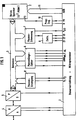
- the electronic text generator shown in FIG. 1 has a control device 1 containing a microprocessor, which is likewise of a construction known per se and is not explained in more detail. All control signals that control the other switching stages are emitted by this control device and the corresponding response signals are recorded and processed
- the device shown in FIG. 1 has a data memory 2, which in the present case is assumed to be made up of electrically programmable and erasable read-only memories, so-called EEPROMs.
- the texts entered as analog electrical signals during the recording first go to an analog / digital converter 4 and then via a serial / parallel converter 5 to a data bus line 3, via which they are fed to the data memory 2, the addressing being via a Address bus 11 is carried out by the control device 1.
- the data is taken from the data memory 2, via the data bus line 3 to the device 5, which is effective in this case as a parallel / serial converter, and from there via the device, which is effective as a digital-analog converter Level 4 and the low-frequency circuits, not shown, on the telephone line, also not shown.
- a pause on the data bus line 3 is represented as a "pause word" of the form 10101010 (AA hex) or 01010101 (55 hex).
- the length of a break can thus be determined by counting and storing the number of immediately following break breaks of the form specified above. This is done, as can be seen from Fig. 1, by means of a pause detection device 7, the mode of operation of which is explained below.
- the pause length is counted by means of a pause length counter 6, which is also described in more detail below.
- the pause length counter 6 triggers a device 8 for pause generation, which generates pause words in the manner explained in more detail below on the data bus line 3, which are fed to the parallel-serial converter 5 and converted by the digital-analog converter 4 into speech pauses will.
- a pause end signal is emitted and the further reading of text data from the data memory 2 is resumed.
- the pause detection device 7 also triggers a time circuit, the structure of which is known per se, will not be explained further below and may, for example, contain a flip-flop that can be set to different values.
- a time schedule 9 for example, three different pause lengths can be specified, with which, for example, the following can be achieved:
- the recording is interrupted and the recording is started again immediately if a first pause length of two seconds is exceeded.
- the corresponding signal is given by the timing circuit 9 to the input Z1 of the control device. This ensures that there is no unnecessarily long speech pause when a text is played back. If there are pauses within a recording which are longer than a second predetermined pause value of, for example, two seconds, the timing circuit 9 outputs a signal to the input Z2 of the control device, which causes these pauses to be normalized to a value of two seconds. This ensures that there are no unnecessarily long speech pauses that occur accidentally during the recording, even within a recording. Finally, at the end of the recording, with a pause length above a third predetermined pause value of, for example, eight seconds, a signal is given to the input Z3 of the control device and the recording is thus interrupted.
- the programming pulses for the electrically programmable and erasable read-only memories contained in the data memory Z are generated by a pulse stage 10 which is connected to the supply voltage via the output U of the control device and receives corresponding programming signals via the output PR.
- the pulse stage 10 is also explained in more detail below.
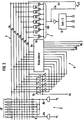
- the pause detection device 7 consists of a gate circuit constructed from the EXNOR gates U1 to U7 and an AND gate U8 in the manner shown in FIG. 2. It can be seen directly from the circuit that a signal appears at the output of the AND gate U8 when one of the two break words explained in more detail above is present on the data bus line 3, the fact via line 7a the pause and via line 7b the type of pause according to the value "0" or "1" on line 3a is given to the input P1 / 2 of the control device 1 shown together.
- the pause length counter 6 consists on the one hand of a binary counter 6a, from the control device 1 via Z the signals for the counting steps, via AW a signal to distinguish between playback and recording, via WL a signal for reading in the pause length and for presetting the counter , a reset signal is given via R, while the end of the pause signal is sent from the counter to the control device 1 via O. If the capacity of the binary counter 6a is exceeded during the upward counting process, the binary counter 6a sends an overflow signal to the control device 1 via the input O. From the control device 1, the maximum length of the counted pause is then stored in the data memory 2, the binary counter 6a is reset, the pause word is stored again and the binary counter 6a is started again in the forward direction.
- the binary counter 6a When pauses are taken, the binary counter 6a counts the pause words and, at the end of the counting process, outputs a circuit 6b which consists of the controllable switches assigned to the individual branches 3a to 3h of the data bus line 3 and which are controlled by the control device 1 via the output AL will; a signal corresponding to the counted pause value on the data bus line 3, which, as already explained, is stored in the data memory 2 following the first pause word.
- the preset binary counter 6a runs backwards and thus causes the pause generating device 8 to be controlled via the outputs P1 and P2 of the control device 1, the output P1 being able to be assigned to the first-mentioned type of a pause word and the output P2 to the second-mentioned type of a pause word.
- the break words are generated in such a way that a voltage UB characterizing the value "1" is applied to the lines 3a to 3h and then by the signal fed from P1 via line 8a or from P2 via line 8b and diodes D. in each case the lines 3b, 3d, 3f, 3h or 3a, 3c, 3e, 3g are set to the value "0".
- the pause words explained above then arise on the data bus line 3 as long as the binary counter 6a is running in reverse.
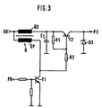
- the programming pulses are generated by the already mentioned programming pulse stage 10, which is shown in more detail in FIG. 3.
- the pulse transformer Ü has a pulse transformer Ü, in which one end of the primary winding ÜP and the secondary winding ÜS is connected to the supply line carrying the supply voltage UB.
- the primary winding ÜP of the transformer Ü is connected to ground via a switching transistor P1.
- the control pulses are given from the output PR of the control device 1 to the base of the switching transistor T1, when it is switched through, a pulse is generated in the secondary winding US, the magnitude of which depends on the winding ratio and the voltage UB to which the capacitor C1 is charged, is added.
- the pulse is emitted via a second switching transistor T2 and, as can be seen from FIG., Reaches the input P1 for the programming pulses of the data memory 2.
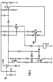
- FIG. 4 shows a switch-on trigger stage with which the operating voltage UB is to be applied to all stages of the electronic text generator shown in FIG. 1, in particular the control device and the microprocessor, only when the input voltage UO, which is the result of switching on of the high capacitance value of capacitor C2 rises relatively slowly, exceeds an intended minimum value
- the trigger circuit contains a first switching stage characterized by switching transistors T3 and T4, via which a bistable relay Q is activated when a predetermined value of the input voltage UD is reached. When relay Q is activated, contact q switches over and the operating voltage UB is applied to the individual stages of the text generator.
- the switch-on trigger stage itself is switched off again, so that it does not draw any quiescent current from the telephone line.
- a signal is sent to the input OFF of a further stage identified by the switching transistors T5 and T6, through which the bistable relay Q is reset and the contact q is switched over, so that the switch-on trigger stage is ready for a new switch-on operation from this moment on.
- the stage identified by the switching transistor T7 comes into operation, by means of which the bistable relay Q is likewise reset via the switching transistors T5 and T6 and the switch-on trigger stage is switched to operational again.
Landscapes
- Engineering & Computer Science (AREA)
- Computer Networks & Wireless Communication (AREA)
- Signal Processing (AREA)
- Telephonic Communication Services (AREA)
- Telephone Function (AREA)
- Financial Or Insurance-Related Operations Such As Payment And Settlement (AREA)
Claims (11)
Priority Applications (1)
| Application Number | Priority Date | Filing Date | Title |
|---|---|---|---|
| AT83103210T ATE25452T1 (de) | 1982-04-17 | 1983-03-31 | Elektronischer textgeber zur abgabe und/oder aufnahme von texten ueber eine fernsprechleitung. |
Applications Claiming Priority (2)
| Application Number | Priority Date | Filing Date | Title |
|---|---|---|---|
| DE3214249A DE3214249C1 (de) | 1982-04-17 | 1982-04-17 | Elektronischer Textgeber zur Abgabe und/oder Aufnahme von Texten ueber eine Fernsprechleitung |
| DE3214249 | 1982-04-17 |
Publications (4)
| Publication Number | Publication Date |
|---|---|
| EP0092083A2 EP0092083A2 (fr) | 1983-10-26 |
| EP0092083A3 EP0092083A3 (en) | 1985-01-30 |
| EP0092083B1 EP0092083B1 (fr) | 1987-02-04 |
| EP0092083B2 true EP0092083B2 (fr) | 1991-12-18 |
Family
ID=6161184
Family Applications (1)
| Application Number | Title | Priority Date | Filing Date |
|---|---|---|---|
| EP83103210A Expired - Lifetime EP0092083B2 (fr) | 1982-04-17 | 1983-03-31 | Emetteur de messages électronique pour la transmission et/ou l'enregistrement de messages sur une ligne téléphonique |
Country Status (3)
| Country | Link |
|---|---|
| EP (1) | EP0092083B2 (fr) |
| AT (1) | ATE25452T1 (fr) |
| DE (2) | DE3214249C1 (fr) |
Families Citing this family (7)
| Publication number | Priority date | Publication date | Assignee | Title |
|---|---|---|---|---|
| DE3840306A1 (de) * | 1988-11-30 | 1990-05-31 | Telefonbau & Normalzeit Gmbh | Verfahren fuer die textkommunikation zwischen an kommunikations-vermittlungsanlagen angeschlossenen endgeraeten, insbesondere fernsprechendgeraeten |
| DE3940332A1 (de) * | 1989-12-06 | 1991-06-13 | Grundig Emv | Teilnehmereinrichtung zur uebertragung zwischengespeicherter nachrichten ueber ein nachrichtennetz fuer vermittelte verbindungen |
| DE4035861A1 (de) * | 1990-11-10 | 1992-05-14 | Grundig Emv | Teilnehmerendeinrichtung mit einem schreib-/lesespeicher mit mindestens zwei speicherbereichen variabler groesse |
| DE4203436A1 (de) * | 1991-02-06 | 1992-08-13 | Koenig Florian | Datenreduzierte sprachkommunikation |
| DE4402901A1 (de) * | 1994-02-02 | 1995-08-03 | Sel Alcatel Ag | Vorrichtung und Verfahren zur Speicherung und Wiedergabe von digitalen Daten |
| FI20001913A7 (fi) | 2000-08-30 | 2002-03-01 | Nokia Mobile Phones Ltd | Menetelmä ja järjestely häiriön vähentämiseksi |
| EP1533962B1 (fr) * | 2003-11-21 | 2015-11-11 | Nokia Solutions and Networks GmbH & Co. KG | Procédé et dispositif de suppression d'interférences dans la bande de fréquences utile d'un signal analogique de sortie |
Family Cites Families (11)
| Publication number | Priority date | Publication date | Assignee | Title |
|---|---|---|---|---|
| US3681656A (en) * | 1970-09-23 | 1972-08-01 | Ikor Inc | High power wide bandwidth pulse generator |
| US3990050A (en) * | 1974-09-25 | 1976-11-02 | Bell Telephone Laboratories, Incorporated | Computer controlled automatic response system |
| DE2854401C2 (de) * | 1978-12-16 | 1983-04-28 | Deutsche Fernsprecher Gesellschaft Mbh Marburg, 3550 Marburg | Anrufbeantworter |
| US4272810A (en) * | 1978-12-21 | 1981-06-09 | Bell Telephone Laboratories, Incorporated | Arrangement for deleting trailing message portions |
| DE3003545A1 (de) * | 1980-01-31 | 1981-08-06 | Alois Zettler Elektrotechnische Fabrik GmbH, 8000 München | Telefonanrufbeantworter |
| DE3024688A1 (de) * | 1980-06-30 | 1982-01-28 | Siemens AG, 1000 Berlin und 8000 München | Telefonanrufbeantworter |
| DE3119226C2 (de) * | 1981-05-14 | 1983-04-28 | Neumann Elektronik GmbH, 4330 Mülheim | "An eine Fernsprechleitung angeschlossener elektronischer Textgeber" |
| DE3119080C2 (de) * | 1981-05-14 | 1985-12-12 | Neumann Elektronik GmbH, 4330 Mülheim | Automatischer Anrufbeantworter |
| DE3125105C2 (de) * | 1981-06-26 | 1984-06-20 | Deutsche Fernsprecher Gesellschaft Mbh Marburg, 3550 Marburg | Schaltung in einem Fernsprechapparat zum Speisen eines Tastenwahlblocks |
| DE3209181A1 (de) * | 1982-03-13 | 1983-09-22 | Deutsche Fernsprecher Gesellschaft Mbh Marburg, 3550 Marburg | Speiseschaltung fuer fernsprechapparate |
| DE3239105C2 (de) * | 1982-10-22 | 1985-03-07 | Deutsche Fernsprecher Gesellschaft Mbh Marburg, 3550 Marburg | Speiseschaltung in einem Fernsprechapparat |
-
1982
- 1982-04-17 DE DE3214249A patent/DE3214249C1/de not_active Expired - Lifetime
-
1983
- 1983-03-31 AT AT83103210T patent/ATE25452T1/de not_active IP Right Cessation
- 1983-03-31 DE DE8383103210T patent/DE3369780D1/de not_active Expired
- 1983-03-31 EP EP83103210A patent/EP0092083B2/fr not_active Expired - Lifetime
Also Published As
| Publication number | Publication date |
|---|---|
| EP0092083A2 (fr) | 1983-10-26 |
| EP0092083B1 (fr) | 1987-02-04 |
| EP0092083A3 (en) | 1985-01-30 |
| DE3214249C1 (de) | 1990-10-04 |
| DE3369780D1 (en) | 1987-03-12 |
| ATE25452T1 (de) | 1987-02-15 |
Similar Documents
| Publication | Publication Date | Title |
|---|---|---|
| EP0012864B1 (fr) | Appareil téléphonique | |
| DE2357254A1 (de) | Schutzvorrichtung fuer speicher mit verschwindendem informationsgehalt | |
| DE69412360T2 (de) | Energieleitungsverbindungsschaltung und entsprechender Schalter mit integrierter Schaltung | |
| EP0092083B2 (fr) | Emetteur de messages électronique pour la transmission et/ou l'enregistrement de messages sur une ligne téléphonique | |
| EP0050301A1 (fr) | Circuit d'attaque pour un relais bistable | |
| EP0065097B1 (fr) | Générateur électronique de messages raccordé à une ligne téléphonique | |
| DE2848921A1 (de) | Vorrichtung zur gewaehrleistung einer bevorzugten ablaufeinrichtung eines magnetbandes in einer in zwei ablaufrichtungen betreibbaren aufnahme- und wiedergabevorrichtung | |
| DE3236830C2 (de) | Elektronische Uhr mit Schallspeicherung | |
| EP0078862A1 (fr) | Dispositif d'appel de secours | |
| EP0057853B2 (fr) | Dispositif électronique pour la délivrance de messages | |
| CH638937A5 (de) | Automatischer anrufbeantworter. | |
| DE3518737C2 (fr) | ||
| DE3002788A1 (de) | Telefonanrufbeantworter | |
| DE1565388A1 (de) | Schutzeinrichtung fuer elektroerosive Metallbearbeitung | |
| DE2126456A1 (de) | Datenübertragungsanordnung | |
| DE2134927A1 (de) | Verfahren zur ruecklauf-fernsteuerung und schaltung hierfuer | |
| DE2703377C2 (de) | Automatische Steuerschaltung für Diktier-Wiedergabegeräte | |
| DE2931436C2 (de) | Schaltungsanordnung zum Überwachen einer Eingangsspannung | |
| DE3701919C1 (de) | Verfahren zur Reduzierung der Energieaufnahme einer Fernsprecheinrichtung,deren Versorgung mit elektrischer Energie ueber die Fernsprechleitung erfolgt,sowie Einrichtung zur Druchfuehrung des Verfahrens | |
| DE2803202C2 (de) | Schaltungsanordnung zur Datensicherung von in als flüchtige (volatile) Speicher ausgebildeten Schreib-Lese- Speichern (RAM) gespeicherten Informationen | |
| DE3325676A1 (de) | Schaltungsanordnung zum anschliessen eines mit einem modem verbundenen datenendgeraetes und einer automatischen waehleinrichtung an eine anschlussleitung einer waehlvermittlungsanlage, insbesondere einer fernsprech-waehlvermittlungsanlage | |
| EP0565036A2 (fr) | Système pour l'interrogation automatique à distance et/ou pour la transmission automatique d'un texte parlé sur une bande par le téléphone | |
| DE1956154C (de) | Anordnung zur Anzeige von Betriebsunterbrechungen eines Datenübertragungssystems, insbesondere eines Faksimile-Systems | |
| EP0050254B1 (fr) | Elément électronique temporisé | |
| DE2059797C (de) | Taktversorgungsanlage |
Legal Events
| Date | Code | Title | Description |
|---|---|---|---|
| PUAI | Public reference made under article 153(3) epc to a published international application that has entered the european phase |
Free format text: ORIGINAL CODE: 0009012 |
|
| AK | Designated contracting states |
Designated state(s): AT CH DE GB IT LI LU NL SE |
|
| PUAL | Search report despatched |
Free format text: ORIGINAL CODE: 0009013 |
|
| AK | Designated contracting states |
Designated state(s): AT CH DE GB IT LI LU NL SE |
|
| 17P | Request for examination filed |
Effective date: 19850122 |
|
| GRAA | (expected) grant |
Free format text: ORIGINAL CODE: 0009210 |
|
| AK | Designated contracting states |
Kind code of ref document: B1 Designated state(s): AT CH DE GB IT LI LU NL SE |
|
| REF | Corresponds to: |
Ref document number: 25452 Country of ref document: AT Date of ref document: 19870215 Kind code of ref document: T |
|
| ITF | It: translation for a ep patent filed | ||
| REF | Corresponds to: |
Ref document number: 3369780 Country of ref document: DE Date of ref document: 19870312 |
|
| PLBI | Opposition filed |
Free format text: ORIGINAL CODE: 0009260 |
|
| 26 | Opposition filed |
Opponent name: N.V. PHILIPS' GLOEILAMPENFABRIEKEN Effective date: 19870918 |
|
| NLR1 | Nl: opposition has been filed with the epo |
Opponent name: N.V. PHILIPS' GLOEILAMPENFABRIEKEN. |
|
| PGFP | Annual fee paid to national office [announced via postgrant information from national office to epo] |
Ref country code: SE Payment date: 19910220 Year of fee payment: 9 |
|
| ITTA | It: last paid annual fee | ||
| PG25 | Lapsed in a contracting state [announced via postgrant information from national office to epo] |
Ref country code: SE Effective date: 19910401 |
|
| PUAH | Patent maintained in amended form |
Free format text: ORIGINAL CODE: 0009272 |
|
| STAA | Information on the status of an ep patent application or granted ep patent |
Free format text: STATUS: PATENT MAINTAINED AS AMENDED |
|
| 27A | Patent maintained in amended form |
Effective date: 19911218 |
|
| AK | Designated contracting states |
Kind code of ref document: B2 Designated state(s): AT CH DE GB IT LI LU NL SE |
|
| REG | Reference to a national code |
Ref country code: CH Ref legal event code: AEN |
|
| NLR2 | Nl: decision of opposition | ||
| NLR3 | Nl: receipt of modified translations in the netherlands language after an opposition procedure | ||
| EPTA | Lu: last paid annual fee | ||
| EUG | Se: european patent has lapsed |
Ref document number: 83103210.7 Effective date: 19911218 |
|
| PGFP | Annual fee paid to national office [announced via postgrant information from national office to epo] |
Ref country code: DE Payment date: 19950328 Year of fee payment: 13 |
|
| PGFP | Annual fee paid to national office [announced via postgrant information from national office to epo] |
Ref country code: LU Payment date: 19960201 Year of fee payment: 14 |
|
| PGFP | Annual fee paid to national office [announced via postgrant information from national office to epo] |
Ref country code: AT Payment date: 19960228 Year of fee payment: 14 |
|
| PGFP | Annual fee paid to national office [announced via postgrant information from national office to epo] |
Ref country code: GB Payment date: 19960327 Year of fee payment: 14 |
|
| PGFP | Annual fee paid to national office [announced via postgrant information from national office to epo] |
Ref country code: NL Payment date: 19960331 Year of fee payment: 14 |
|
| PGFP | Annual fee paid to national office [announced via postgrant information from national office to epo] |
Ref country code: CH Payment date: 19960514 Year of fee payment: 14 |
|
| PG25 | Lapsed in a contracting state [announced via postgrant information from national office to epo] |
Ref country code: DE Effective date: 19961203 |
|
| PG25 | Lapsed in a contracting state [announced via postgrant information from national office to epo] |
Ref country code: LU Free format text: LAPSE BECAUSE OF NON-PAYMENT OF DUE FEES Effective date: 19970331 Ref country code: LI Effective date: 19970331 Ref country code: GB Effective date: 19970331 Ref country code: CH Effective date: 19970331 Ref country code: AT Effective date: 19970331 |
|
| REG | Reference to a national code |
Ref country code: CH Ref legal event code: AEN Free format text: AUFRECHTERHALTUNG DES PATENTES IN GEAENDERTER FORM |
|
| PG25 | Lapsed in a contracting state [announced via postgrant information from national office to epo] |
Ref country code: NL Effective date: 19971001 |
|
| REG | Reference to a national code |
Ref country code: CH Ref legal event code: PL |
|
| GBPC | Gb: european patent ceased through non-payment of renewal fee |
Effective date: 19970331 |
|
| NLV4 | Nl: lapsed or anulled due to non-payment of the annual fee |
Effective date: 19971001 |